Version 4.
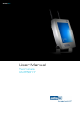
Terminals VMT5017 Product Portfolio Copyright © ads-tec GmbH Raiffeisenstr.14 D-70771 Leinfelden-Echterdingen Germany 2 © ads-tec GmbH • Raiffeisenstr.
Terminals VMT5017 INDEX ABOUT US .......................................................................................................................................... 5 1 REMARKS ................................................................................................................................. 6 1.1 RELEVANT DOCUMENTATION FOR THIS DEVICE ................................................................................. 6 1.2 USED SYMBOL EXPLANATION ....................................
Terminals VMT5017 7.2 8 SOFTWARE & DRIVER INSTALLATION .......................................................................................... 31 8.1 INSTALLING THE OPERATING SYSTEM ........................................................................................... 31 8.2 TOUCHSCREEN DRIVER INSTALLATION .......................................................................................... 32 8.3 SOFT KEYBOARD ..............................................................................
Terminals VMT5017 Pos: 1 /Datentechnik/Allgemeine Hinweise/Wir über uns/Wir über uns @ 0\mod_1158743732668_681.doc @ 692 @ ABOUT US ads-tec GmbH Raiffeisenstr. 14 70771 Leinfelden-Echterdingen Tel: +49 (0) 711 / 45894-0 Fax: +49 (0) 711 / 45894-990 www.ads-tec.
Terminals VMT5017 1 REMARKS 1.1 RELEVANT DOCUMENTATION FOR THIS DEVICE The following documents are essential for setting up and operating this device: USER MANUAL ON SERVICE CD (DOCUMENTATION ON HAND): Contains information for installation, commissioning and operating the device along with technical data of the device hardware. SERVICE CD: Contains drivers and the user manual. Note: The "Drivers-xx.
Terminals VMT5017 1.4 TRADE MARKS We would like to remind you that all software and hardware designations as well as trade names of companies used in this documentation are subject to the general, international trade mark, brand or patent protection laws. WINDOWS®, WINDOWS® CE and WINDOWS® CE.net™ are trade marks registered by Microsoft Corp. Citrix® and ICA® are trade marks registered by Citrix Systems Inc. Intel® and Pentium® are trade marks registered by Intel Corp.
Terminals VMT5017 1.6 ENVIRONMENTAL CONDITIONS The device may be operated under the following conditions. Failure to observe these specifications will terminate any warranty for this device. Ads-tec cannot be held liable for any damages arising due to improper use and handling. • Temperature for devices including a HDD: In operation For storage 0 … 40° C -20 … 60° C (Because of the integrated max.
Terminals VMT5017 1.
Terminals VMT5017 1.9 SCOPE OF DELIVERY Please check that all of the following components are contained in the packaging: • 1 device • 3 pin Feed-through connector from Phoenix Contact, COMBICON MC 1.5/3-STF-3.81 type (already connected with the device socket) • Service CD Optional scope of delivery • Operating system • Installation kit • 2.4 GHz WLAN antennas, enclosed for b/g Pos: 11 /Datentechnik/Betriebshinweise/Betriebsort/Betriebsort für VMT-Serie @ 0\mod_1158826710817_681.
Terminals VMT5017 2 OPERATING INSTRUCTIONS This device contains electrical voltages and extremely sensitive components. The manufacturer, or a service partner authorised by the manufacturer, should be consulted if you plan to make any modifications. For this type of work, the device must be switched off at the mains and the power lead must be disconnected. Suitable measures for avoiding electrostatic discharge towards parts of the components when touching the equipment must be taken.
Terminals VMT5017 2.3 WARRANTY / REPAIR During the warranty period any repair must only be carried out by the manufacturer or by a person authorised by the manufacturer. Pos: 14 /Datentechnik/Montage/Montagemöglichkeiten/Montagemöglichkeit für VMT 5017 @ 1\mod_1227001419097_681.doc @ 4183 @ 12 © ads-tec GmbH • Raiffeisenstr.
Terminals VMT5017 3 INSTALLATION 3.1 INSTALLATION OPTIONS Gallow bracket for Rittal systems The stainless steel installation bracket for gallow type installations (CP-S/CP-L) has four drill holes. By using this bracket, the device can be fixed on a gallows. You can set the angle of the device towards the front or rear in several steps by loosening the self-locking screws on both sides, in order to set up the angle of viewing. © ads-tec GmbH • Raiffeisenstr.
Terminals VMT5017 Bracket for VESA standard The stainless steel installation bracket for the VESA standard (75mm) has four drill holes. Using this bracket, the device can be fitted to a wall or to a VESA coupler. You can set the angle of the device towards the front or rear in several steps by loosening the self-locking screws on both sides, in order to set up the angle of viewing. 14 © ads-tec GmbH • Raiffeisenstr.
Terminals VMT5017 Desktop bracket The stainless steel bracket for desktop installation has 12 drill holes. By using this bracket, the device can be fixed to a control stand or desktop. You can set the angle of the device towards the front or rear in several steps by loosening the self-locking screws on both sides, in order to set up the angle of viewing. © ads-tec GmbH • Raiffeisenstr.
Terminals VMT5017 Bracket for 90° installation The stainless steel bracket for angled installation in a 90° angle allows a flexible use. It has four drill holes for fixing the device. You can set the angle of the device towards the front or rear in several steps by loosening the self-locking screws on both sides, in order to set up the angle of viewing. 16 © ads-tec GmbH • Raiffeisenstr.
Terminals VMT5017 Customer-specific brackets For manufacturing of customer specific brackets, you'd have to consider that the bolts on the device side are fixed, and cannot be removed. Note: The figure on this page shows a VMT 5015 device. The VMT fixing points for a customerspecific bracket are the same with all VMT devices. Pos: 15 /Datentechnik/Montage/Montageskizzen/Außenabmessungen des Geräts/Montageskizzen/Außenabmessungen für VMT 5017 @ 0\mod_1171445406585_681.
Terminals VMT5017 3.2 EXTERNAL DEVICE DIMENSIONS Pos: 16 /Datentechnik/Inbetriebnahme/Systemmerkmale/Inbetriebnahme für VMT 50xx-Serie @ 0\mod_1158845383048_681.doc @ 792 @ 18 © ads-tec GmbH • Raiffeisenstr.
Terminals VMT5017 4 COMMISSIONING The power supply connection and interfaces of this device are installed inside the case. You have to remove the case cover in order to connect the power supply cables and the interface cables. All supply leads and all required data leads have to be connected before commissioning.
Terminals VMT5017 4.2 CABLE INSTALLATION The power supply connectors and interfaces of this device are installed inside the case. Cables can be routed through rubber grommets and exit the case on the bottom. The grommets are inserted between the case and the cover, and can easily be removed after removing the cover. Since this device includes the required input peripherals (soft keyboard / touch screen), only one grommet for the power supply cable (cable diameter of 6...
Terminals VMT5017 5 OPERATION 5.1 FRONT CONTROL KEYS Depending on the equipment version of the device, an operating system (Windows CE.net, Windows XP embedded or Windows XP Prof.) and a soft keyboard might be already installed ex factory.
Terminals VMT5017 5.2 SOFT KEYBOARD If the operating system is installed ex works, the soft keyboard is included in this installation. If the device is delivered without any operating system, the soft keyboard has to be installed by the customer. By using the soft keyboard, data can be entered via the touchscreen like with an external keyboard. HOW TO OPERATE THE SOFT KEYBOARD FROM VERSION 3.
Terminals VMT5017 5.3 TOUCHSCREEN The control system is equipped with an touchscreen. The touchscreen is internally connected with a serial interface. The driver software required for its use is already integrated in the corresponding operating system, or can be installed from the attached service CD. Pos: 23 /Datentechnik/Bedienung/Status-Anzeigen/SYS-LED/SYS-LED für OPC / CPC / PLC / OTC / ITC / VMT (+Monitore) - Serie / IPC 5100 / 5300 / 5500 / 1100 @ 1\mod_1204714132162_681.doc @ 3406 @ 5.
Terminals VMT5017 6 INTERFACES 6.1 INTERFACE SETUP INTERFACE IRQ ADDRESS COM1 4 3F8h COM2 (Touch) 3 2F8h Pos: 25 /Datentechnik/Schnittstellen/Serielle Schnittstelle COM RS232/Serielle Schnittstelle COM (RS232) für OPC / IPC / CPC / PLC / OTC / ITC / VMT / MSA-Serie @ 0\mod_1158925008814_681.doc @ 871 @ 6.2 SERIAL COM INTERFACE (RS232) The serial interface is used for digital and for analogue data transmission as well.
Terminals VMT5017 6.3 USB CONNECTIONS The USB interfaces are used for connecting peripherals with USB connection. The interface complies with the USB 2.0 standard. PIN NUMBER SIGNAL NAME 1 VDC 2 D- 3 D+ 4 GND Note: The USB interfaces may be locked using the Lock USB You'll find this software and the documentation on the service CD. software tool. USB CONNECTION ON THE FRONT PANEL One USB interface can be accessed from the front.
Terminals VMT5017 6.4 EXTERNAL KEYBOARD One mouse and one keyboard can be connected with both existing PS2 connectors. These connections are colour coded for proper connection with this device. PIN NUMBER SIGNAL NAME 1 Data 2 NC 3 GND 4 +5V 5 Clock 6 NC The control system has a purple coloured 6-pin mini-DIN socket (PS2) identified as “KEYB". Any commercially available AT-compatible quality keyboard equipped with the required connector can be connected with this socket.
Terminals VMT5017 6.6 24V DC POWER SUPPLY The power supply voltage is supplied via a feed-through clamp including screw connection (figure shows socket in the device). PIN NUMBER SIGNAL NAME 1 24V DC 2 Ignition contact (24V) 3 0V DC Voltage tolerance In the equipment version with a 24V DC ±20% power supply, a DC-DC converter is integrated. • Input voltage: 24V DC ±20%. Current consumption The current consumption of the device at nominal consumption depends on the equipment version of this device.
Terminals VMT5017 IGNITION FUNCTION The device is capable of being externally started by using an additional signal input. This function is well known from the automotive industry (switch-on by using an ignition contact). The device is here continuously supplied with a 24V DC power supply, and only if the additional signal is present at the ignition contact, e.g. as a result of turning the ignition key of the forklift, the computer is switched on or the blocking is released.
Terminals VMT5017 6.7 NETWORK CONNECTION (RJ45) If the drivers required for functioning are installed on the device, the control system may be integrated in an Ethernet network supporting the 10/100 Mbit standard by using the Ethernet 10/100BaseT network connector. Specifications of this network topology must be observed in this case. You can install the drivers required for functioning from the enclosed service CD, should they not be installed on the device.
Terminals VMT5017 7 DRIVES 7.1 HARD DRIVES / COMPACT FLASH DRIVES (IDE INTERFACE) The storage medium is selected according to the customer requirements. The following options are available for storage: Compact Flash memory: Compact flash memories with a storage capacity of at least 64 MB are used. The capacity depends on the desired operating system and the additional programmes to be installed. Hard disk: A 2.5" hard disk with at least 20 GB (UDMA) is used.
Terminals VMT5017 8 SOFTWARE & DRIVER INSTALLATION The device will be delivered with a pre-installed Windows operating system on request by the customer. The drivers required for this are already installed, and the operating system will be enabled by entering the licence information. Should an initial installation be required, please adhere to the following steps.
Terminals VMT5017 8.2 TOUCHSCREEN DRIVER INSTALLATION Note: When installing the drivers, you have to consider that the touchscreen is connected with the serial interface! Touchscreen and PS2 mouse can be used simultaneously Installation must be carried out as described below: • Switch on PC and boot • Start the installer file in the touchscreen folder by accessing the service CD with the Windows Explorer. • Follow the instructions on screen and agree to the licensing conditions.
Terminals VMT5017 9 TECHNICAL DETAILS 9.1 DISPLAY DATA Display 9.2 17" TFT, 1440 x 900 pixels (WXGA) Display colours max. 262k Farben Touchscreen Resistive industrial touchscreen COMPUTER DATA This device may be equipped with the following adsX modules ex factory (according to customer requirements). VERSION 1 Pentium M 1.1 GHz 256MB - 2GB DDR RAM Intel 855 GME VERSION 2 Celeron M 1.
Terminals VMT5017 10 SERVICE AND SUPPORT The ads-tec company and their partner companies offer a comprehensive service and support to your customers providing a quick and professional support in case of any question with respect to ads-tec products and components. Since the devices from ads-tech company are also used by partner companies, these devices might be configured according to customer requirements.