ARESCOM NetDSL 800 ADSL Modem version 5.
Copyright © Copyright 1996, 1997, 1998, 1999, 2000 ARESCOM, Inc. All rights reserved. No part of this documentation or software may be reproduced or distributed in any form without prior written permission from ARESCOM, Inc. ARESCOM, Inc. has the right to make revisions and to change the contents of this document without any obligation to provide prior notice of such revisions and changes. ARESCOM, Inc.
Table of Contents 1. Before You Begin 1.1 1.2 1.3 1.4 Hot Features ......................................................... 1-1 Package Includes ................................................. 1-1 Minimum System Requirements ........................ 1-2 Information You Will Need .................................. 1-2 2. Hardware Installation 2.1 2.2 2.3 2.4 2.5 2.6 2.7 Diagram of the NetDSL ........................................ 2-1 Safety First .................................................
Table of Contents 5. Configuration 5.1 5.2 5.3 5.4 5.5 5.6 Configuration ....................................................... 5-1 Outline of Configuration ...................................... 5-2 General Configuration ......................................... 5-3 LAN Configuration ............................................... 5-6 DSL Configuration ............................................... 5-8 Configuration File .............................................. 5-11 6. Status Feature 6.1 6.
Before You Begin 1 This Chapter Includes: 1.1 Hot Features........................................... 1-1 1.2 Package Includes ................................... 1-1 1.3 Minimum System Requirements............. 1-2 1.4 Information You Will Need ...................... 1-2 1.1 Hot Features Bridge Packet Filtering Table You can monitor and restrict the traffic flow through your NetDSL modem.
Minimum System Requirements 1.3 Minimum System Requirements • ADSL line • 10BaseT Ethernet or USB interface • CD-ROM drive NetDSL gives you the option of configuring the modem using the Arescom NetDSL Manager. The system requirements for each are listed below: Using the NetDSL Manager: • Ethernet card • PC* with at least a 486 microprocessor (Pentium® recommended) • CD-ROM drive • At least 4 MB of space available on the hard disk drive • Microsoft® Windows® 95/98/2000 or Windows® NT 4.
Hardware Installation 2 This Chapter Includes: 2.1 Diagram of the NetDSL .......................... 2-1 2.2 Safety First ............................................. 2-3 2.3 Setup Instructions................................... 2-3 2.4 Connect to the Ethernet.......................... 2-4 2.5 Connect to the ADSL Interface............... 2-6 2.6 Connect to the USB Interface................. 2-7 2.7 Connect to Power ................................... 2-8 2.
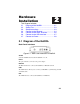
Hardware Installation Front Panel Interfaces Figure 2.2 Front Panel Interfaces for NetDSL PWR (Power) A green LED is ON when power is supplied to the NetDSL. DIAG (Diagnostic) The yellow DIAG LED is an indicator that shows the NetDSL modem has been successfully booted up and the software is functional. When NetDSL is powered on, the DIAG LED flashes while the router is booting up. After 10 to 15 seconds, the DIAG LED stops flashing and remains off.
Hardware Installation 2.2 Safety First Personal Safety • In case of emergency, locate the closest electricity power-off switch. • Refrain from touching any active wires or terminals. • Remove jewelry before working on equipment connected to electricity. • Keep cables away from walkways. • Dispose of this product in accordance with national laws and regulations. Product Handling • Keep ventilation slots clear. • Operate in a clean and dust-free location.
Hardware Installation 2.4 Connect to the Ethernet Step 1. Locate your Ethernet cable (included). Step 2. Attach the Ethernet cable to the Ethernet interface of your NetDSL. Step 3. Plug in the loose end of the Ethernet cable to your Ethernet network. Option 1. Attach the included Ethernet cable to the Ethernet port on a PC. Figure 2.3 Connecting to a Ethernet Port on a PC Option 2. Attach the included Ethernet cable to the uplink port on a hub. Figure 2.
Hardware Installation ports on a hub. Figure 2.5 Connecting to the Non-Uplink Port on a Network Hub Step 4. The LAN LINK LED on the front panel should be lit green to indicate a valid Ethernet connection. If the LAN LINK LED is not lit, then repeat steps 1 through 3. Note: See Appendix B Ethernet Cable Pinout for further information about the differences between a straight-through cable and a crossover cable.
Hardware Installation 2.5 Connect to the ADSL Interface Step 1. Plug the RJ-11 connector end of the ADSL phone cable (included) in the DSL interface of the modem. The ADSL phone cable is provided (RJ-11 to RJ-45). Step 2. Connect the RJ-45 connector end of the ADSL phone cable to the ADSL outlet on the wall. Figure 2.
Hardware Installation 2.6 Connect to the USB Interface Step 1. Plug the Type-B (square-shaped) end of the USB detachable cable (included) into the USB port of the modem. Step 2. Plug the Type-A (flat-shaped) end of the USB detachable cable into the USB port of your PC. Step 3. Do not turn on the power switch until software installation is complete. Proceed to Section 3.11 “Installing the Software Drivers.” Figure 2.
Hardware Installation 2.7 Connect to Power Step 1. Plug the power adapter in the Power interface of the NetDSL. Step 2. Connect one end of the power cord to the power adapter, and insert the other end of the power cord to the power outlet on the wall. Step 3. To activate the NetDSL, turn the ON/OFF switch to ON. Figure 2.
Software Installation f 3 This Chapter Includes: 3.1 About TCP/IP.......................................... 3-1 3.2 Detecting TCP/IP in Windows® 95/98.... 3-1 3.3 Installing TCP/IP in Windows® 95/98..... 3-2 3.4 Configuring TCP/IP in Windows® 95/98 3-2 3.5 Detecting TCP/IP in Windows® 2000..... 3-3 3.6 Installing TCP/IP in Windows 2000 ........ 3-3 3.7 Configuring TCP/IP in Windows® 2000 . 3-4 3.8 Detecting TCP/IP in Windows® NT 4.0 .. 3-4 3.9 Installing TCP/IP in Windows® NT 4.0... 3-5 3.
Installing TCP/IP in Windows® 95/98 A. If you see TCP/IP listed under Network Components, you already have TCP/IP on your Windows® 95/98. Proceed to configuration directions for Windows® 95/98 in Section 3.4. B. If you do not see TCP/IP listed under Network Components, you do not have TCP/IP on your Windows® 95/98. Proceed to the next section, “Installing TCP/IP in Windows® 95/98.” 3.3 Installing TCP/IP in Windows® 95/98 Step 1. From the Configuration tab in the Network window, click Add. Step 2.
Detecting TCP/IP in Windows® 2000 To enable static IP addressing Step 1. Click Specify an IP Address and then type the IP Address and Subnet Mask (for your PC). Step 2. Click the Gateway tab. Step 3. Type in your Gateway IP Address (the LAN IP address for the NetDSL) from your ISP and then click Add. Step 4. Click the DNS tab. Enter the Host name, Domain name, and DNS Service Search Order (for your LAN) and then click Add. Step 5. Click OK to exit TCP/IP Properties window and click OK to exit Network.
Configuring TCP/IP in Windows® 2000 Step 3. Choose the Internet Protocol (TCP/IP) icon from the Network Protocol list box, then click OK. Step 4. Check to see if Internet Protocol (TCP/IP) is listed under Network Components. A. If you do not see TCP/IP listed under Network Components, you have not installed TCP/IP. Repeat steps 1 - 4. B. If you see TCP/IP listed under Network Components, you already have TCP/IP on your Windows 2000. Proceed to “Configuring TCP/IP in Windows 2000” in the next section. 3.
Installing TCP/IP in Windows® NT 4.0 3.9 Installing TCP/IP in Windows® NT 4.0 Note: Consult your Network Administrator if you do not have authorization to change settings for your PC. Step 1. From the Protocols tab in the Network window, click Add. Step 2. Select TCP/IP Protocol listed under Network Protocols, Click OK. Step 3. Check to verify that TCP/IP is listed under Network Protocols, then Click OK. A. If you do not see TCP/IP listed under Network Protocols, you have not installed TCP/IP.
Installing the Software Drivers 3.11 Installing the Software Drivers Your PC should have detected the USB to Ethernet as soon as the USB cable is plugged in. The following instructions will help you complete the USB installation procedure. Step 1. After your PC detects an USB connection, a message window appears to indicate that the software driver installation process is about to begin. Click Next to start the installation process. Figure 3.1 USB Installation Step 1 Step 2.
Installing the Software Drivers Figure 3.2 USB Installation Step 2 Step 3. Now you need to select where you would like Windows to search for the proper files. Insert the included CD or floppy disk into either your CDROM or floppy disk drive. Select the appropriate options for CD or floppy disk, and click the Next button to continue. Figure 3.3 USB Installation Step 3 Step 4. Windows is now reading your CD to search for the proper files.
Installing the Software Drivers continue. Figure 3.4 USB Installation Step 4 Step 5. After Windows has installed the software driver files from the CD, it will need to install some files from your Windows 98 CD to complete the software driver installation. A message window appears to ask you to insert your Windows 98 CD. Insert your Windows 98 CD into your CD-ROM drive and click OK.
Installing the Software Drivers Figure 3.5 USB Installation Step 6 Step 7. Windows prompts the next message to ask you to restart your computer. Click Yes to reboot your system. This is highly recommended for your PC to properly recognize the new network settings. Figure 3.6 USB Installation Step 7 Congratulations!!! You have successfully installed your NetDSL using USB. The USB LED on the front panel should be lit yellow to indicate a valid USB connection.
Installing the Software Drivers 3-10 NetDSL Software User’s Guide
NetDSL Manager 4 This Chapter Includes: 4.1 Installing the NetDSL Software............... 4-1 4.2 Launching the NetDSL Manager ............ 4-1 The NetDSL Manager gives you access to the configuration and administrative controls for the NetDSL. Install the NetDSL software on PCs that you want to give access to these controls.
NetDSL Manager For further information on the available features, refer to the NetDSL Manager Overview later in this section. Note: After the initial modem configuration, you can reset the modem configuration parameters at any time from the Tools feature. Just select the Reset Router/Mode tab, click on the “Delete Configurations and Reset to Manufacturer Mode” box, and then click Reset Router.
NetDSL Manager Figure 4.2 Subnet window If the NetDSL Manager is unable to detect the modem or it gives you an error message, consult the on-line help menu for more detailed instructions. To continue, select a modem and click Enter. You will automatically enter the NetDSL Manager. From the NetDSL Manager you can use any one of the following features: • Configuration to get your modem up and running. • Status to monitor many of your modem’s operations.
NetDSL Manager NetDSL Manager Overview The NetDSL Manager gives you access to all of the features of the NetDSL. To activate a feature, you may use the keyboard by following table below. Note that both lower and uppercase letters may be used. The letters to be used with the Alt key to activate the Configuration, Status, and Tools figure are underlined in the NetDSL Manager. Alternatively, you may select the feature using your mouse pointer.
NetDSL Manager • Status—allows you to remotely monitor many of the modem’s functions, such as Front Panel LED operation, the Traffic Counter, and the DSL Status Table. • Tools.—provides you with some tools for performing some basic modem maintenance tasks, firmware upgrades, and resetting the modem.
NetDSL Manager 4-6 NetDSL Software User’s Guide
Configuration 5 This Chapter Includes: 5.1 Configuration .......................................... 5-1 5.2 Outline of Configuration.......................... 5-2 5.3 General Configuration ............................ 5-3 5.4 LAN Configuration .................................. 5-6 5.5 DSL Configuration .................................. 5-8 5.6 Configuration File ..................................5-11 5.
Configuration 5.2 Outline of Configuration With the Configuration feature you have the flexibility to configure one parameter at any time and to change more technical default settings. The Configuration window is organized in a hierarchical tree format. From the NetDSL Manager, click General Configuration to access the General Configuration window. Click on the item that you wish to configure, and then set the parameters.
Configuration 5.3 General Configuration Administrative Security The first configuration panel in the NetDSL General Configuration is the Administrative Security. From this panel, you can create a Router Name and select Password Protected for administrative security. Naming your modem is mandatory. The default name for the modem is “NetDSL.” If you are concerned with administration security, you should select Password Protected.
Configuration this panel, you can Add New Bridge Packet Filter, Modify Bridge Packet Filter, or Remove Bridge Packet Filter. Figure 5.2 Bridge Packet Filter Add New Bridge Packet Filter To add a new IP Packet Filter, click the New button. This will open the Add New Bridge Packet Filter window. Figure 5.3 Add New Bridge Packet Filter Enter the Bridge packet filter parameters according to the following criteria: MAC: Identifies each device on the network and the Internet.
Configuration Discard: Packet is blocked and discarded. Pass to next filter: Packet goes to the next filter in sequence. When you are finished, click OK. If you do not want to create an bridge packet filter, click Cancel to close the Add New Bridge Packet Filter window. Modify Bridge Packet Filter If you want to change the parameters of an bridge packet filter, select the filter number, and then click Modify. This will open the Modify Bridge Packet Filter window.
Configuration 5.4 LAN Configuration LAN Configuration From Configuration, use the list in the left panel to open the LAN Configuration menu. LAN Configuration assigns the IP address of the modem on your LAN, and defines the range of IP addresses that the modem can locally access from that IP Address (its subnet). The LAN Interface can be configured for either a single or multiple IP address account. Figure 5.
Configuration NetDSL. Click Exit to return to the NetDSL Manager.
Configuration 5.5 DSL Configuration DSL Configuration From Configuration, double-click on the DSL Configuration icon. To create a new ATM PVC interface, select the appropriate DSL line mode and double-click on the Make New ATM PVC icon. Figure 5.5 DSL Configuration You have the option to use ANSI T1.413, G.Lite, G.DMT, or Multi Mode as your DSL line mode. To find out which DSL line mode works better with your unit, please consult your ISP or telephone company.
Configuration ATM PVC Properties After typing in the name and clicking OK, the ATM PVC Properties panel will appear. Note that a maximum of 8 PVCs may be defined. If you double-click on the icon of a previously created PVC, the ATM PVC Properties panel will also appear. Figure 5.6 ATM PVC Properties The ATM PVC Properties panel allows you to change the name of the selected ATM interface and to set the values of Virtual Path Identifier (VPI) and the Virtual Channel Identifier (VCI).
Configuration ATM Service Type Click on ATM Service Type in the left panel. Figure 5.7 ATM Service Type This panel allows you to select the ATM Service Type for the ATM interface. Presently, Unspecified Bit Rate (UBR) and Constant Bit Rate (CBR) are available. You can specify the Peak Cell Rate (PCR) in kbps. This panel also allows you to specify the period for the Operations And Maintenance (OAM) F5 (virtual channel) timer. If the period is set to zero, the OAM F5 loopback cell is not sent.
Configuration 5.6 Configuration File From Configuration, double-click on the Configuration File icon, then doubleclick on the Configuration File to open the menu. The Save Configuration File feature allows you to save your custom configuration settings to your local hard disk drive as a configuration file (*.cfg). This is especially helpful for network management. Figure 5.8 Save Configuration File To keep the current configuration setting that you just entered in the NetDSL: Step 1.
Configuration 5-12 NetDSL Software User’s Guide
Status Feature 6 This Chapter Includes: 6.1 Main Status Panel .................................. 6-1 6.2 LED Panel .............................................. 6-3 6.3 Traffic Counter ........................................ 6-4 6.4 DSL Status Table.................................... 6-5 Status feature collects information from many different functions and operations and displays the information within a single, convenient panel.
Status Feature window. Figure 6.2 Event Log in Status The Event Log helps you pinpoint the date and time a connectivity problem occurred. Every time you close Status the Event Log will reset. If you want to save the contents of the log you may do so by clicking on the Save Event Log button and saving the file to your computer’s hard drive or to a 3.5” floppy disk. To close the Event Log, click the Close button. To exit Status and return to the NetDSL Manager, click the Close button.
Status Feature 6.2 LED Panel From the NetDSL Manager click on the Status icon, click on the Show Details button, and then select the LED Panel tab. Depending on where your modem is located, you may have difficulty viewing the front window LEDs of the NetDSL. The LED Panel tab provides a real-time display of the front window LEDs and the DSL Line Upstream and Downstream speeds in Kbps. Figure 6.3 LED Panel Tab in Status To return to the Main Status panel, click the Hide Details button.
Status Feature 6.3 Traffic Counter From the NetDSL Manager click on the Status icon, click on the Show Details button, and then select the Traffic Counter tab. The Traffic Counter tab displays real-time data traffic counters for the LAN interface and the DSL interface. For each interface, cumulative totals are displayed for Sent Packets, Received Packets, Sent Bytes, and Received Bytes. Figure 6.4 Traffic Counter Tab in Status To return to the Main Status panel, click the Hide Details button.
Status Feature 6.4 DSL Status Table From the NetDSL Manager click on the Status icon, click on the Show Details button, and then select the DSL Status Table tab. The DSL Status Table tab displays all the user-defined ATM interfaces and protocol configuration. For each ATM interface listed, the DSL Status Table will show the ATM PVC Name, Encapsulation Type, Sent Packets, Received Packets, and NAT IP address. Figure 6.
Status Feature 6-6 NetDSL Software User’s Guide
Tools Feature 7 This Chapter Includes: 7.1 Upgrade Firmware.................................. 7-1 7.2 Reset Router/Bridge ............................... 7-3 The NetDSL Manager provides you with some tools for performing basic modem maintenance tasks, such as firmware upgrades and resetting the modem. To access the Tools Feature, launch the NetDSL Manager and click on the Tools icon. 7.1 Upgrade Firmware Click Tools in the NetDSL Manager, and then select the Upgrade Firmware tab.
Tools Feature Figure 7.
Tools Feature 7.2 Reset Router/Bridge Click Tools in the NetDSL Manager, and then select the Reset Router tab. You can reset your modem from the Reset Router tab. Select the Delete Configurations and Reset to Manufacture Mode checkbox if you want to remove all your custom settings while resetting your modem. Otherwise, if you do not select the checkbox, the modem will simply reboot. Figure 7.
Tools Feature 7-4 NetDSL Software User’s Guide
Troubleshooting 8 This Chapter Includes: 8.1 Cannot Detect the Modem...................... 8-1 8.2 Modem and PC are Not in the Same Subnet.......................................... 8-2 8.3 Cannot Upgrade the Firmware ............... 8-2 If you can not find the answers to your problems here, consult the help menu in the NetDSL Manager or refer to the FAQs located on -ARESCOM’s website (http://www.arescom.com). 8.1 1. Cannot Detect the Modem Verify that your modem is connected to your Ethernet LAN.
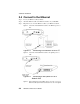
Modem and PC are Not in the Same Subnet 8.2 Modem and PC are Not in the Same Subnet 1. Your modem and PC must be in the same subnet. Otherwise, you will not be able to access the NetDSL Manager and configure your modem. Verify that you have entered the correct information provided by your Internet Service Provider (ISP) for your modem’s and PC’s IP Address and Subnet Mask. For more specific information about your account, consult your ISP. 8.3 Cannot Upgrade the Firmware 1.
About Configuration Parameters A When you order Internet service your provider will give you a great deal of information. A list of the information presented to you by the remote network you will be dialing (ISP, company server, POP account) is provided to you in Section 1.4 “Information You Will Need.” Definitions of common configuration terms are available below. Please note that terminology used by various remote networks may vary. Explaining IP Addresses LAN Interface vs.
Terminology for Configuration Parameters discriminate between different virtual connections and ATM nodes. Virtual Channel Identifier Each connection in an ATM network is characterized by a Virtual Channel (VC). This is a header subfield that is assigned manually when NetDSL is used. A VC has only local significance on the link between ATM nodes. When the connection is released, the VC value on the involved links will be released and can be reused by other connections.
Ethernet Cable Pinout B B-1
B-2 NetDSL Software User’s Guide
Warranty Information C Limited Warranty ARESCOM warrants its hardware products to be free from defects in workmanship and materials, under normal use and service, for the period of three (3) years from the date of purchase from ARESCOM or its Authorized Reseller. Full three (3) year coverage requires registration. This warranty applies to the original purchaser (“Customer”) of this product only.
Warranties Exclusive will be billed for repairs. ARESCOM will not be held responsible for product(s) lost or damaged during transit. ARESCOM has the right to refuse any products received without a RMA number. The repaired or replaced item will be shipped to Customer, at ARESCOM’s expense, no later than thirty (30) days after receipt by ARESCOM. This warranty is not valid if the serial number has been tampered with or removed from the product(s).
Warranty Registration Warranty Registration In order to receive warranty repairs on the NetDSL, you must register the product with ARESCOM within thirty (30) days of the original purchase date. This information will be used for customer and technical support access as well as notification of new software releases and product enhancements that could be of value to you. Your warranty is valid for three (3) years from the data of purchase.
Return Instructions C-4 NetDSL Software User’s Guide
D Declaration of Conformity Application of Council Directives 89/336/EEC. Standards to which the conformity is declared: EN55022-Class B EN50082-1 Manufacturer’s Name: ARESCOM, Inc. Manufacturer’s Address: 3451 Gateway Blvd. Fremont, CA 94538 Tel: (510) 445-3638 Fax: (510) 445-3636 Type of Equipment: ADSL Modem, ITE Model Name: NetDSL Tested By: Bay Area Compliance Laboratory, Corp.