Security Services Inc.
Fire Alarm System Limitations While a fire alarm system may lower insurance rates, it is not a substitute for fire insurance! An automatic fire alarm system–typically made up of smoke detectors, heat detectors, manual pull stations, audible warning devices, and a fire alarm control with remote notification capability–can provide early warning of a developing fire. Such a system, however, does not assure protection against property damage or loss of life resulting from a fire.
Installation Precautions Adherence to the following will aid in problem-free installation with long-term reliability: WARNING - Several different sources of power can be connected to the fire alarm control panel. Disconnect all sources of power before servicing. Control unit and associated equipment may be damaged by removing and/or inserting cards, modules, or interconnecting cables while the unit is energized.
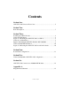
Contents Section One: ADT-UZC-256 Universal Zone Coder ......................................................... 5 Section Two: Board Description ......................................................................................... 7 Section Three: Installing the ADT-UZC-256 ....................................................................... 8 Unimode II Installation .................................................................................
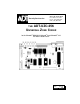
Section One: ADT-UZC-256 Universal Zone Coder General The ADT-UZC-256 Universal Zone Coder provides separate codes for up to 256 initiating zones. Each code requires a different initiating circuit. Only one Notification Appliance Circuit is required, but coded output from the ADT-UZC-256 can be fed to many output circuits. Coded Outputs The ADT-UZC-256 contains three outputs, each rated for three amps at 30 VDC.
Mounting The ADT-UZC-256 plugs into the ICA-4L in Unimode 2020/1010 systems, or mounts behind modules in the Unimode 4-16 and Unimode II. Additional Reference The ADT-UZC-256 Zone Coder can be used with the Unimode 4-16, the Unimode II, and the Unimode 2020/1010 Fire Alarm Control Panels.
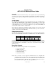
Section Two: Board Description TROUBLE LED (Yellow) Power Supervision Lights when one or more trouble conditions are detected. ALARM TEST (Red) Follows the main coded output. EIA-232 Connection* Female DB-9 connector for programming from an IBM-compatible computer. SLC ON-LINE LED (Green) Blinks during communication with the master FACP. EIA-485 Connection* All connections are power limited and supervised. See diagram below for terminal assignment.
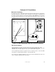
Section Three: Installing the ADT-UZC-256 Unimode II Installation Mechanical Installation The ADT-UZC-256 mounts beneath the third and fourth modules, to the right of the CPU. The ADT-UZC-256 fastens to the base of the CHS-4 chassis using the four hex standoffs (provided), which are screwed onto four PEM studs. The ADT-UZC-256 is then attached to three of the four standoffs using the mounting screws provided (see Figure 3 - 1).
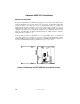
Unimode 4-16 Installation Mechanical Installation In a Unimode 4-16, the ADT-UZC-256 mounts beneath the third (right most) module. The ADT-UZC-256 fastens to the back of the box using three hex standoffs (one aluminum and two nylon provided), which are screwed into the three female PEM nuts as shown. The ADT-UZC-256 is then attached to two of the four standoffs using captive screws on the board (see Figure 3 - 2).
Unimode 2020/1010 Installation Mechanical Installation In a Unimode 2020/1010, the ADT-UZC-256 plugs into a slot on the ICA-4L chassis. If the Unimode 2020/1010 is in an A-size cabinet (only one ICA-4L), the ADT-UZC-256 mounts beneath the CPU or the SIB. If a second or third ICA-4L chassis is available, the ADT-UZC-256 should be mounted in one of the two upper slots to permit easy access to ADT-UZC-256 wiring and switch settings.
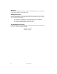
Section Four: Power/NAC Configurations These two Notification Appliance Circuits share 3.0 amps of coded power. ADT-UZC256 ADT-UZC256 These six Notification Appliance Circuits share 3.0 amps of coded power. ADT-UZC256 These ten Notification Appliance Circuits share 3.0 amps of coded power. These two Notification Appliance Circuits share 3.0 amps of coded power. ADT-UZC256 These four Notification Appliance Circuits share 3.0 amps of coded power.
These two Notification Appliance Circuits share 3.0 amps of coded power. ADT-UZC256 ADTAPS-6R These eight Notification Appliance Circuits share 3.0 amps of coded power. These two Notification Appliance Circuits share 3.0 amps of coded power. ADT-UZC256 ADTAPS-6R These four Notification Appliance Circuits share 3.0 amps of coded power. These four Notification Appliance Circuits share 3.0 amps of coded power. ADTAPS-6R These two Notification Appliance Circuits share 3.0 amps of coded power.
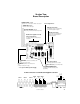
Section Five: Unimode 2020/1010 / ADT-UZC-256 Configuration LIB-200A CCM-1 ADT-SIB-NET CPU-2020 EIA-232 CRT ADT-LCD-80 EIA-485 SLC XPM XPP-1 XPC-8 Universal Zone Coder ADT-UZC-256 ARM-4 3 AMP MAX. Bell Power BATTERY BATTERY 51349:D 4/25/00 UZC-2020.
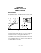
Section Six: ADT-UZC-256 Connections to M300CADT Modules The following illustration shows connections to an M300CADT control module. For wiring other types of control modules, refer to the specific literature for that module. System Sensor A2143-00 (Canada: N-ELR) End-of-Line Resistor, 47K, .
Power Input 1 Coded Output 1 Power Input 2 Coded Output 2 Power Input 3 Coded Output 3 Appendix A: Plug/Terminal Schematic 3 Code Relay 3 Coded Outputs 2 1 Code Relay 2 Code Relay 1 51349:D 4/25/00 15