Security Services Inc. One Town Center Road Boca Raton, FL 33431 Phone: (561) 988-3600 FAX: (561) 988-3675 The ADT-UDACT udactnot.
Fire Alarm System Limitations While a fire alarm system may lower insurance rates, it is not a substitute for fire insurance! An automatic fire alarm system–typically made up of smoke detectors, heat detectors, manual pull stations, audible warning devices, and a fire alarm control with remote notification capability–can provide early warning of a developing fire. Such a system, however, does not assure protection against property damage or loss of life resulting from a fire.
Installation Precautions Adherence to the following will aid in problem-free installation with long-term reliability: WARNING - Several different sources of power can be connected to the fire alarm control panel. Disconnect all sources of power before servicing. Control unit and associated equipment may be damaged by removing and/or inserting cards, modules, or interconnecting cables while the unit is energized.
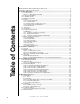
Table of Contents 4 NFPA Standards, NFPA 72 National Fire Alarm Code ................................................................... 6 Underwriters Laboratories Documents ............................................................................................ 6 1.0 Product Description ................................................................................................................ 7 1.1 Product Features .................................................................................
Table of Contents 5.0 Reporting Formats ................................................................................................................. Table 5-1: Data Reporting Structure ............................................................................... Table 5-2: Letter Code Definitions ................................................................................... Table 5-3: Ademco Contact ID Reporting Structure ....................................................... 6.
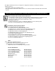
This digital communicator has been designed to comply with standards set forth by the following regulatory agencies: • Underwriters Laboratories Standard UL 864 • NFPA Standards 72 National Fire Alarm Code for Local, Remote Station and Central Station Fire Alarm Systems Before proceeding, the installer should be familiar with the following documents. NFPA Standards, NFPA 72 National Fire Alarm Code: • Central Station Fire Alarm Systems (Automatic, Manual and Waterflow) Protected Premises Unit.
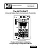
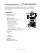
1.0 Product Description The Universal Digital Alarm Communicator/Transmitter (ADT-UDACT) may be used with a variety of ADT control panels (refer to Appendices). The ADT-UDACT transmits system status to UL Listed Central Station Receivers via the public switched telephone network. The ADT-UDACT, which is compact in size, mounts internally in some panels or externally in a separate enclosure. EIA-485 annunciator communications bus and 24 volt (nominal) connections are required.
Primary Phone Line Secondary Phone Line Modular Cables P/N MCBL-7 (Order Separately) Comm Fail Output (power-limited) 24VDC Power in (use power-limited source) 24 VDC (power-limited) EIA-485 Connector (use power-limited source) udactfea.
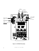
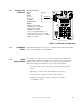
1.2 Controls and Indicators Front Panel Switches CLEAR TEST MODE Up Arrow Down Arrow 1st EVENT ENTER/STORE Digits 0-9 A B C DO NOTUSE D E F udactfea.wmf Displays • EIA-485 - yellow LED • COMM. FAIL - yellow LED • KISS OFF - green LED • POWER - green LED • Four, Seven Segment Displays - red • Primary Phone Line Active - red LED • Secondary Phone Line Active - red LED • TEST - green LED Figure 1-2: Controls and Indicators 1.3 Compatible Panels 1.
• For tone burst or touchtone type formats: Discern proper 'Ack' and 'Kiss-off' tone(s) - The frequency and time duration of the tone(s) varies with the transmission format. The ADT-UDACT will adjust accordingly. • Communicate in the following formats (refer to Section 6.
1.7 Specifications DC Power - TB1, Terminals 1 & 2 24VDC (nominal) filtered, nonresettable and power-limited. Voltage range is 21.2 to 28.2 volts. DC Power TB1 Terminals 1 (+), 2 (-) 40 mA in standby, 75 mA max. while communicating and 100 mA with the open collector output engaged and communicating. Data Communications - TB1, Terminals 3 - 7 EIA-485 serial interface, TB1 Terminal 3 = RS+, 4 = RS-, 5= Shield, 6 = Future use, 7 = Future use. Power-limited source must be used.
If the control panel causes harm to the telephone network, the telephone company reserves the right to temporarily discontinue service. Advance notification will be provided except in cases when advance notice is not practical. In such cases, notification will be provided as soon as possible. The opportunity will be given to correct any problems and to file a complaint. DO NOT CONNECT THIS PRODUCT TO COIN TELEPHONE, GROUND START, OR PARTY LINE SERVICES.
1.9.6 Clear Function: When the clear function is activated, it causes the ADT-UDACT to immediately stop transmissions, hang-up from the telephone network, clear out any messages that were waiting for transmission and reset. 1.9.7 Manual Test Function: The manual test function allows for a test report message to be sent to both Central Stations upon activation.
2.0 Installation and Wiring 2.1 General Mounting Options For information on mounting the ADT-UDACT in a specific fire alarm control panel, refer to the appropriate Appendix. 2.2 Output Circuits Telephone Circuits Provision to connect to two independent telephone lines is available via two telephone jacks labeled PH1 (Primary) and PH2 (Secondary). Telephone line control/ command is possible via double line seizure as well as usage of an RJ31X style interconnection.
Relay Driver The ADT-UDACT's open collector output on TB3, terminal 2 is provided for Communicator Failure and ADT-UDACT trouble. It can be used to drive UL listed relay MR-101/C or MR-201/C. The output is rated for 40 mA. The normal condition for the output is Off (deenergized). Communicator Failure occurs when the maximum number of attempts to reach both central stations has taken place or when both phone lines are disconnected.
SLC Loop to Fire Alarm Control Panel M300 Series Monitor Module Wiring in same room as ADT-UDACT All wiring to relay must be in the same room within 20 feet of ADT-UDACT and in conduit. 3.9K EOL Resistor (included) ON NC Earth Grnd Comm Fail +24 VDC C 0 NO 18/24 115 udactrbl.wmf 230 ADT-UDACT MR-101/C (MR-201/C may be used) Note: M300 Series Monitor Module is used to supervise Normally Closed output of MR-101/C.
UL Powerlimited Wiring Requirements Power-limited and nonpower-limited circuit wiring must remain separated in the cabinet. All power-limited circuit wiring must remain at least 0.25" away from any nonpower-limited circuit wiring. Furthermore, all power-limited circuit wiring and nonpower-limited circuit wiring must enter and exit the cabinet through different knockouts and/or conduits. A typical wiring diagram for the ADT-UDACT is shown below.
3.0 Programming Instructions Programming Mode Programming of the ADT-UDACT is possible at any time including while the ADT-UDACT is communicating with a Central Station. The ADT-UDACT has been designed for many different types of applications. After examining your specific application, review the programming options and choose the entries best suited for your system. The ADT-UDACT has a built-in programmer.
Throughout programming mode, the first three locations on the left of the display represent the memory address which can range from 00 to 208 (Alpha characters are not used). The last location (farthest right) represents the contents of the memory address. The first address displayed is shown below: 00_F (address)(data) 3.2 Switch Functions The Function of each switch in program mode is shown below: No function in this mode - Select operating mode - Increment memory address { UDACTKEY.
Primary Number Communication Format (16) One location is needed to select the Communication Format to the primary phone number. Address 16 is used for this purpose. The default (factory setting) for this address is 16_A, which is 4+2 Standard, 1800 Hz 'Carrier', 2300 Hz 'ack'. You may enter 0, 1, 2, 4, 6, 8, C or E in place of the default, then press [ENTER/STORE].
Secondary Number Communication Format (42). Programming is the same as the primary number's Comm Format at address 16. Default entry is 'A', 4+2 Standard. When selecting the Format, note that Ademco Contact ID is the only format in the ADT-UDACT which identifies the specific zone or point status to the Central Station. All other formats report the number of zones or points that are active but do not identify the specific zone or point.
Point Repor ting Zone Reporting (Factory Default) Unimode 400 START Addr. 52-53 END Addr. 54-55 111 121 1 = Reports status of up to 99 zones START Addr. 52-53 END Addr. 54-55 Unimode 2020/1010, ADT-MNNA 012 322 Unimode 400 113 193 2 = Repor ts status of up to 2,040 points 3 = Repor ts status of up to 384 points Note: For additional information on the starting and ending addresses, refer to the host FACP Technical Manual.
Loop Number (64 - 65) For Contact ID format only. Factory default is '00'. Maximum value is '97'. Refer to Section 5.0 for additional information. Device/Zone Number (66 - 68) For Contact ID format only. These entries apply to the general reports only, i.e. general alarm, general trouble, general supervisory. Factory default is '000'. Maximum value is '999'. Refer to Section 5.0 for additional information.
Programming the Real-Time Clock Entering an address greater than 209 will cause a display of the current time. On initial power up, the clock will start running from the factory setting of 00:01 (military time). The far left digit will be flashing, indicating that this is the first digit to be programmed. Hours/Minutes Select a digit then press [ENTER/STORE]. The digit 2nd from the left will start flashing. Select a digit then press [ENTER/STORE]. Hours setting is complete.
4+2 Standard and 4+2 Express Formats If '1, A or C' are entered for address 16, the following data is automatically programmed for the Primary phone number event codes. Enter a '0' for the data setting to disable the report. These formats do not support zone/point programming. For zone/point reporting, refer to Contact ID.
Ademco Contact ID Format If 'E' is entered for address 16, the following data is automatically programmed for the Primary phone number event codes. Enter a '000' for the data setting to disable the report.
3+1, 4+1 Express or 4+1 Standard Formats If '0, 2, 4, 6 or 8' are entered for address 42, the following is automatically programmed for the Secondary phone number event codes. Enter a '0' for the data setting to disable the report. These formats do not support zone/point programming. For zone/point reporting, refer to Contact ID.
4+2 Standard and 4+2 Express Formats If '1, A or C' are entered for address 42, the following is automatically programmed for the Secondary phone number event codes. Enter a '0' for the data setting to disable the report. These formats do not support zone/point programming. For zone/point reporting, refer to Contact ID.
Ademco Contact ID Format If 'E' is entered for address 42, the following data is automatically programmed for the Secondary phone number event codes. Enter a '000' for the data setting to disable the report.
UDACTKEY.WMF 4.0 Operating Instructions 4.1 Normal Mode The ADT-UDACT has five Modes of operation; Normal, Program, Lamp Test, Troubleshoot and Type mode. Upon initial power up, the system will be in Normal Mode. This section discusses operation of the ADT-UDACT in the Normal Mode. 4.1.
1st EVENT DOWN ARROW UP ARROW [ENTER/STORE] This key along with the Up Arrow and Down Arrow keys, are used to display ADTUDACT fault conditions. Press the 1st Event key at any time to display the first event that occurred. Use the Down Arrow key to view other ADT-UDACT fault events (older) that have occurred and are active - not cleared yet. Use the Up Arrow key to view other ADT-UDACT fault events (newer), that have occurred and are active - not cleared yet.
Primary Line Secondary Line Modem LED Primary Active Secondary Active LED UDACTNOT.WMF Kiss-Off LED Figure 4-1: ADT-UDACT Phone Connectors and LEDs 4.1.3 Normal Mode Operation: Normal mode is the standard mode of operation. In this mode, the ADT-UDACT monitors host FACP status, power input, EIA-485 communications and telephone line voltage. The four character 7-segment display is normally off and does not annunciate events that are being transmitted.
Two phone numbers must be programmed, the Primary phone number and the Secondary phone number. All system reports will be transmitted to the primary phone number. Reports will automatically be sent to the secondary phone number if attempts to transmit to the primary phone number are unsuccessful. If 10 total attempts to communicate are unsuccessful, the Communicator Failure output will be turned on (TB3, terminal 2). Note that as an option, all reports may also be sent to the secondary phone number.
For all pulsed formats and both Ademco Express formats, the zone/point report is repeated per the total number of zones or points activated once factory default entries of zero are removed. See Tables 3-2, 3-3, 3-4, 3-5, 3-6 and 3-7. When Ademco Contact ID format is used, the actual zone or point activated is identified in the report.
To access Type Mode, press the MODE key followed by the 4-digit code 8973 and then press the [ENTER/STORE] key. The ADT-UDACT will display three digits. For example, initial entry will display 01 0. The characters to the left identify the zone or point number. In this example, 01 identifies zone 01 or point address 01.
4.2.2 Zone or Point Supervisory A zone or point must be defined as supervisory to allow the ADT-UDACT to identify the correct report to transmit to the central station. Follow the programming instructions in the FACP manual to program a zone or point as supervisory. Next, program the zone or point as a code 2 for supervisory. Use the charts in Appendices to enter point and zone definitions. Note that the ADT-UDACT fire protection and reporting capabilities are inactive while in Type Mode. 4.
UDACTNOT.WMF Both Primary and Secondary Lines Figure 4-2: Handset/Speaker Connection 4.4 Lamp Test Mode To perform a Lamp Test, press MODE then 5267 followed by [ENTER/STORE]. This will test all system LEDs. The LEDs will stay on for five seconds, then the ADT-UDACT will return to normal mode. ☛ 5267 spells LAMP on a Touch-Tone® phone.
5.0 Reporting Formats Table 5-1 shows the data reporting structure for each of the pulsed formats as well as the Ademco Express formats. Ademco Express formats allow a typical data message to be transmitted to the Central Station in under 5 seconds. Pulsed formats typically require 15 to 20 seconds in comparison. Table 5-2 defines each letter code used in Table 5-1. Table 5-3 describes the data reporting structure used for Ademco Contact ID format.
Where: SSS 0r SSSS A A2 RA RA2 TZ TZ2 RTZ RTZ2 TS TS2 RTS RTS2 L L2 RL RL2 P P2 RP RP2 V V2 RV RV2 X X2 XA XA2 = Subscriber ID = Alarm (1st digit) = Alarm (2nd digit) = Alarm Restore (1st digit) = Alarm Restore (2nd digit) = Zone Trouble (1st digit) = Zone Trouble (2nd digit) = Zone Trouble Restore (1st digit) = Zone Trouble Restore (2nd digit) = System Trouble (1st digit) = System Trouble (2nd digit) = System Trouble Restore (1st digit) = System Trouble Restore (2nd digit) = Low Battery (1st digit) = Low
The reporting structure for the Ademco Contact ID format is as follows: SSSS 18 QXYZ GG CCC where SSSS = Four digit Subscriber ID (addresses 17 - 20 and 43 - 46) 18 = Identifies transmission as Contact ID to the receiver at the Central Station Q = Event Qualifier 1 = New Event 2 = New Restore XYZ = Event code (shown in Tables 3-4 and 3-7) GG = Group number or Loop number CCC = Device or Zone number For general reports (alarm, trouble and supervisory), the GG and CCC fields are transmitted as 00 and 000 unle
By using the Type Mode feature, identification of zone/point types is possible.
6.
7.0 Programming Reference Sheets --- To enter Programming, press Mode: 7 7 6 4, Enter ❑ ❑ ❑ ❑ ❑ ❑ ❑ ❑ ❑ ❑ ❑ ❑ ❑ ❑ ❑ ❑ 00 01 02 03 04 05 06 07 08 09 10 11 12 13 14 15 Addresses 00 to 15 store the Primary Phone Number. Enter 'F' to represent the end of the number. ❑ Primary Comm Format: Enter 0 - F. ❑ ❑ ❑ ❑ Primary Account Code: Valid keys are 0-F. ❑ ❑ ❑ ❑ Primary 24-Hour Test Time. Enter military time (i.e. 1400 for 2 PM). ❑ Primary Number Test Time Interval.
Programming Reference Sheet ❑ ❑ ❑ ❑ ❑ ❑ ❑ ❑ ❑ ❑ ❑ 69 82 95 108 121 134 147 160 173 186 199 44 ❑ ❑ ❑ ❑ ❑ ❑ ❑ ❑ ❑ ❑ ❑ 70 83 96 109 122 135 148 161 174 187 200 ❑ ❑ ❑ ❑ ❑ ❑ ❑ ❑ ❑ ❑ ❑ 71 84 97 110 123 136 149 162 175 188 201 ❑ ❑ ❑ ❑ ❑ ❑ ❑ ❑ ❑ ❑ ❑ 72 85 98 111 124 137 150 163 176 189 202 ❑ ❑ ❑ ❑ ❑ ❑ ❑ ❑ ❑ ❑ ❑ ❑ ❑ ❑ ❑ ❑ ❑ ❑ ❑ ❑ ❑ ❑ ❑ ❑ ❑ ❑ ❑ ❑ ❑ ❑ ❑ ❑ ❑ Document 50934 Rev B 73 86 99 112 125 138 151 164 177 190 203 74 87 100 113 126 139 152 16
Programming Reference Sheet Factory Default Settings --- To enter Programming, press Mode: 7 7 6 4, Enter F F F F F F F F F F F F F F F F ❑ ❑ ❑ ❑ ❑ ❑ ❑ ❑ ❑ ❑ ❑ ❑ ❑ ❑ ❑ ❑ 00 01 02 03 04 05 06 07 08 09 10 11 12 13 14 15 Addresses 00 to 15 store the Primary Phone Number. Enter 'F' to represent the end of the number. A ❑ Primary Comm Format: (4+2 Standard 1800/2300). 0 0 0 0 ❑ ❑ ❑ ❑ Primary Account Code. 0 0 0 0 ❑ ❑ ❑ ❑ Primary 24-Hour Test Time. 0000 = 12:00 midnight.
Programming Reference Sheet Factory Default 1 ❑ 0 ❑ F ❑ 0 ❑ E ❑ 9 ❑ F ❑ C ❑ 0 ❑ 8 ❑ E ❑ 69 82 95 108 121 134 147 160 173 186 199 46 1 ❑ F ❑ E ❑ E ❑ C ❑ 9 ❑ 1 ❑ F ❑ 0 ❑ E ❑ F ❑ 70 83 96 109 122 135 148 161 174 187 200 0 ❑ 8 ❑ F ❑ 3 ❑ E ❑ 1 ❑ F ❑ D ❑ E ❑ A ❑ E ❑ 71 84 97 110 123 136 149 162 175 188 201 0 ❑ F ❑ F ❑ E ❑ D ❑ 9 ❑ 6 ❑ F ❑ 2 ❑ E ❑ F ❑ 72 85 98 111 124 137 150 163 176 189 202 8 ❑ A ❑ F ❑ 6 ❑ E ❑ 2 ❑ 0 ❑ E ❑ 0 ❑ B ❑ 9 ❑ 73 86 99 112 125 138 151
Appendix A: Zone Assignments (Unimode 300/400) Zone No. Zone Function Zone No. Zone Function Zone No.
Appendix B: Point Assignments (Unimode 300*/400) Point No. Type of Device Point No.
Appendix B (continued): Point Assignments (Unimode 300*/400) Point No. Type of Device Point No. Type of Device Point No. Type of Device (Detectors Loop 1) (Detectors Loop 1) (Detectors Loop 2) Point No.
Appendix B (continued): Point Assignments (Unimode 300*/400) Point No. Type of Device Point No. Type of Device 401 451 402 452 403 453 404 454 405 455 406 456 407 457 408 458 409 459 410 460 411 461 412 462 413 463 414 464 415 416 417 418 419 420 421 422 423 424 425 426 427 428 429 430 431 432 433 434 435 436 437 438 439 440 441 442 443 444 445 446 447 448 449 450 Note: Event Code cannot be altered. Physical location is critical to the point number reported.
Appendix C: Point Assignments (ADT-MNNA) Note: Use the following charts to carefully identify the function of each point in the system. Take special precaution with any supervisory points in the system. For the ADT-UDACT to report a supervisory point to the central station, both the FACP and the ADT-UDACT must have the point programmed as supervisory. Failure to program the panel or ADT-UDACT correctly will result in a fire alarm signal being transmitted to the central station.
Appendix C (continued): Point Assignments (ADT-MNNA) Point No. Point Function Point No. Point Function Point No.
Appendix C (continued): Point Assignments (ADT-MNNA) Point No. Point Function Point No. Point Function Point No.
Appendix C (continued): Point Assignments (ADT-MNNA) Point No. Point Function Point No. Point Function Point No.
Appendix C (continued): Point Assignments (ADT-MNNA) Point No. Point Function Point No. Point Function Point No.
Appendix D: Unimode 2020/1010 The ADT-UDACT may be mounted in the Unimode 2020/1010 control panel using the CHS-4 chassis or remotely in an ADT-ABS-8RF or ADT-UBS-1F enclosure up to 6000 feet away from the control panel. All power must be removed from the control panel before making any connections to prevent circuit damage. The EIA-485 serial interface is connected between the control panel and ADT-UDACT using twisted, shielded pair wire.
SIB TB5 Terminal 5 EIA-485 (+) Terminal 6 EIA-485 (-) EIA-485 (Supervised and Power-limited TB1 Terminal 3 RS+ Terminal 4 RS- Refer to Figure I-4 for power connections to ADT-UDACT Install 120 ohm EOL resistor (P/N:71244) across terminals 3 & 4 if last or only device on EIA-485 line. Note that Terminals 6 & 7 are not used at this time.
Unimode 2020/1010 cabinet SIB in Unimode 2020/1010 DO NOT USE (Supervised) To Phone Solid Earth Ground Connection Lines AM20ABSU.WMF Install 120 ohm EOL resistor (P/N:71244) across terminals 3 & 4 if last or only device on EIA-485 line. Note that Terminals 6 & 7 are not used at this time. ADT-UDACT in ADT-ABS8RF (Shown with cover removed) Notes: 1) Ferrite cores are recommended for all applications. 2) Recommended wire is 12 AWG to 18 AWG twisted pair.
Appendix E: Unimode 300/400 The ADT-UDACT is capable of reporting a maximum of 99 zones or 448 points when used with the Unimode 400. Remove all power from the control panel by disconnecting AC and batteries. Since the Unimode 400 cannot accommodate the ADTUDACT in the control panel enclosure, the ADT-UDACT must be mounted remotely using an ADT-ABS8RF enclosure. Ferrite cores are recommended for this application. Refer to Figure E-3 and the accompanying notes for wiring alternatives. ABS-8R.
Install 120 watt EOL resistor (PN: 71244) on TB1 terminals 3 and 4 if last or only device on EIA-485 line Unimode 400 Cabinet Supervised and Power-limited EIA-485 and power wiring Ferrite cores PN 29090 To supervised phone lines Solid earth ground ADT-CPU-400 EIA-485 (ACS Mode) TB4-1 (+) TB4-2 (–) MPS-400 TB2-1 (+) TB2-2 (–) 24 VDC Nonresettable power DO NOT USE ADT-UDACT in ADT-ABS8RF (shown with cover removed) Notes: 1) Ferrite cores are recommended for all applications.
Type Mode Programming To disable or identify a zone or point in Type Mode (refer to Section 4.2), the following Entries/Addresses are used: For Zone Identification: Zones 1 - 99 are programmed by Entries/Addresses 01 - 99. The factory default code is 'fire alarm.
Appendix F: ADT-MNNA The ADT-UDACT is capable of reporting up to 2,040 points when used with the ADT-MNNA. The first 568 points can be programmed using the Type Mode feature (refer to Section 4.2). All points greater than 568 can be transmitted only as fire alarm points. For the ADT-UDACT to report a supervisory point to the central station, both the FACP and the ADT-UDACT must have the point programmed as supervisory.
ADT-MNNA TB1 Terminal 3 EIA-485 (+) Terminal 4 EIA-485 (-) TB1 EIA-485 (Supervised and Power-limited TB1 Terminal 3 RS+ Terminal 4 RS- power connections to ADT-UDACT Install 120 ohm EOL resistor (P/N:71244) across terminals 3 & 4 if last or only device on EIA-485 line. Note that Terminals 6 & 7 are not used at this time. ina-udac.
ADT-MNNA ADT-MNNA cabinet DO NOT USE (Supervised) To Phone Solid Earth Ground Connection Lines ina-absu.WMF Install 120 ohm EOL resistor (P/N:71244) across terminals 3 & 4 if last or only device on EIA-485 line. Note that Terminals 6 & 7 are not used at this time. ADT-UDACT in ADT-ABS8RF (Shown with cover removed) Notes: 1) Ferrite cores are recommended for all applications. 2) Recommended wire is 12 AWG to 18 AWG twisted pair. 3) Shielded wire is not required (unless mandated by local AHJ).
Appendix G: Annunciators The ADT-UDACT is connected to the EIA-485 communication bus. AFM series and LDM series annunciators may also occupy the same bus.
Document 50934 Rev B 5/15/00 PN 50934:B
Document 50934 Rev B 5/15/00 PN 50934:B 67
Document 50934 Rev B 5/15/00 PN 50934:B