
User manual

ADT-TP3340DJ Three-axis Dispenser
- 23 -
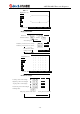
As shown in the figure above, the second point is “Forward circle” and the fourth point is
“Reverse circle”. A full circle is generated if the start points and end points of the forward circle and
reverse circle are set to same value.
Note: The start points and end points of the forward circle and reverse circle must be in same
distance from the center of the circle.
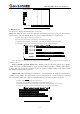
6. Full circle
The full circle is similar to arc point type. The difference is that the full circle determines a circle
through three points on the arc, while the arc determines an arc through three points on the arc.
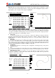
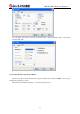
7. Ellipse, ellipse parameters
This system generates an ellipse through two instructions, which consist of ellipse center
coordinates, long/short axis diameter, the plane of the ellipse, start angle, end angle and ellipse
direction. When these parameters are set, an ellipse is generated.
Start angle, end angle: Indicate the start position and end position of the ellipse in the unit of
degree (0-360). If the start angle and end angle are same, it indicates a full ellipse.
Ellipse direction: Clockwise or counterclockwise.
8. Port output
Output switching signal in specified port and the range of output port number is 0-15.
9. Specify glue gun
Specify the glue gun to be opened and closed during processing. Totally eight glue guns are
available. You can specify several glue guns at the same time.
10. Motor reset
Specify one or several axes to reset.
11. Delay pause
Delay for certain period of time and continue the processing. If the delay is set to 0, the
processing will be paused.
12. Waiting for input
The input port signal waiting to be specified is specified value. You can set the waiting overtime.
If there is no signal after that time, it continues processing. If the overtime is set to 0, it indicates that
the machine always waits for the signal.
13. End processing
Stop processing after processing this instruction.
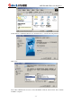
VII. Operation method of double-station processing
First, set the “Station number” in “Manufacturer settings” to double stations. After setting “Double
station Y-axis configuration”, activate the two stations in “Double station switch” in “User parameter
settings”, select two processing files, and press the corresponding running button of the file to be started. If
the processing circulation is set to several, the two processing files run alternatively; for single processing,
one file stops after processing, but if the running button of the other file is pressed during processing, it
processes the other file after processing the current one.
VIII. General operating flow
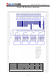
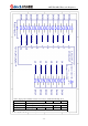
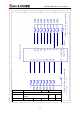
1) Connect the wires according to the wiring diagram
2) Set the parameters according to actual conditions
3) Test whether the wire connection is proper with the hardware test function
Include motor test and I/O test. The motor test is to test whether the motor runs normally
and whether the direction is proper; the input test is to test whether the input signal has been
connected, whether corresponding port is proper, whether the electric level is proper, etc; the
output test is to test whether the output corresponds to proper output point, and whether the
cylinder and relay work normally.
Note: For linear resetting, if the motor runs forwardly, it leaves away from the origin; if the
motor runs reversely, it approaches to the origin. The resetting is in negative direction.
4) Select a file
5) Edit the processing file
6) Test the processing file by running the processing file in single step mode
7) Run the processing file