ADT-CNC4620 CNC4620 Lathe Control System Programming Manual Adtech (Shenzhen) Technology Co., Ltd. Add: F/5, Bldg/27-29, Tianxia IC Industrial Park, Yiyuan Rd, Nanshan District, Shenzhen Postal code: 518052 Tel: 0755-26722719 Email:export@machine-controller.com Fax: 0755-26722718 http://www.machine-controller.
ADT-CNC4620 Programming Manual Copyright Adtech (Shenzhen) Technology Co., Ltd. (Adtech hereafter) is in possession of the copyright of this manual. Without the permission of Adtech, the imitation, copy, transcription and translation by any organization or individual are prohibited. This manual doesn’t contain any assurance, stance or implication in any form.
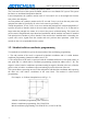
ADT-CNC4620 Programming Manual Version History Item No. First uploaded on Version No. Pages Compiled by XT20101227 2011-5-13 A0101 73 Yang Jipeng XT20101227 2011-11-15 A0201 61 Shi Tingliang Typeset by Revision Date Version/Page Result Confirmed by Remark: above table is only for the version update of the Manual. 1. We have collated and checked this Manual strictly, but we can’t ensure that there are no error and omission in this Manual. 2.
ADT-CNC4620 Programming Manual Precautions ※Transportation and storage The packaging boxes shouldn’t be stacked more than six layers Do not climb onto, stand on or put heavy objects on the packaging box Do not drag or convey the product with a cable connected to the product Do not impact or scratch the panel and display Keep the packaging box away from moisture, insulation and rain ※Unpacking and checking Unpack and check whether the product is the one you ordered Check whether the product is damaged duri
ADT-CNC4620 Programming Manual Contents 1. PROGRAMMING BASICS .................................................................................................... - 1 1.1. 1.2. 1.3. 1.4. 1.5. 1.6. 1.7. 1.8. 1.9. 2. INTRODUCTION OF CNC MACHINE TOOL .............................................................................- 1 DEFINITION OF COORDINATE AXIS .......................................................................................- 2 MACHINE TOOL COORDINATE SYSTEM AND MECHANICAL HOME .......
ADT-CNC4620 Programming Manual 3.2. INTERPOLATION FUNCTION ................................................................................................- 22 3.2.1. Fast moving G00 .......................................................................................................- 22 3.2.2. Linear interpolation G01 ...........................................................................................- 23 3.2.3. Arc interpolation G03, G02 ...........................................................
ADT-CNC4620 Programming Manual 1. Programming Basics 1.1. Introduction of CNC machine tool CNC (Computer Numerical Controler) machine tool consists of CNC system, servo motor (or step motor) drive, machine tool (including headstock, feed drive mechanism, worktable, tool holder, electric control cabinet), etc.
ADT-CNC4620 Programming Manual 1.2. Definition of coordinate axis CNC machine tool is shown in Fig. 1-2-1 Tailstock seat Principal axis seat Tool Too holder Fig. 1-2-1 The system uses the right angle coordinate system constituted with X axis and Z axis. X axis is vertical to the principal axis, and Z axis is parallel to the principal axis. The direction to the workpiece is negative, and the direction from the workpiece is positive.
ADT-CNC4620 Programming Manual mechanical home, and create a machine tool coordinate system with current position as the coordinate origin. Note: If the zero switch isn’t installed on the lathe, it isn’t possible to perform home operation. 1.4. Workpiece coordinate system and program home Workpiece coordinate system is the right angle coordinate system set on the part drawing for programming, which is also called floating coordinate system.
ADT-CNC4620 Programming Manual and the motion control mode is called point-position control. The X axis and Z axis of this system are linked, which is two axes linked CNC system. This system has linear, arc and thread interpolation function. Linear interpolation: the synthetic motion track of X axis and Z axis is the straight line from the start point to the end point.
ADT-CNC4620 Programming Manual 1.6. Conversion between imperial and metric system* Set the unit to imperial or metric with G code (G20, G21). System G code Minimum unit Imperial G20 0.0001 inch Metric G21 0.0001mm The G code for imperial and metric switch should be placed in front of the program. Use separate block instruction before setting the coordinate system. The unit system of the following values changes according to the G code for imperial and metric switch.
ADT-CNC4620 Programming Manual O0001; (program name) G0 X100 Z50; (quickly locate point A) M12; (clamp the workpiece) T0101; (replace tool #1 and execute tool #1 offset) M3 S600; (start the principal axis, and set the principal axis rotation to 600rpm) M8 (coolant on) G1 X50 Z0 F600; (approach point B at the speed of 600mm/min) W-30 F200; (cut from point B to point C) X80 W-20 F150; (cut from point C to point D) G0 X100 Z50; (quickly back to point A) T0100; (cancel tool offset) M5 S0; (stop principal axis)
ADT-CNC4620 Programming Manual Program No. (0000~9999, leading zero can’t be omitted) Instruction address O 2) Instruction word Instruction word is the basic instruction unit for CNC system to complete the control function. Instruction word consists of one English letter (instruction address) and later digits (instruction value, signed or unsigned). Instruction address regulates the meaning of following instruction value.
ADT-CNC4620 Programming Manual 1.9. Main program and subroutine To simplify the programming, if same or similar processing track and control process need to be used for several times, the program instructions of this part can be edited to independent program for calling. The program that calls other programs is called as main program, and the program being called (ended with M99) is called as subroutine. Both subroutine and main program occupy system capacity and storage space.
ADT-CNC4620 Programming Manual 2. M S F T Instruction 2.1. Auxiliary function (M code) M instruction consists of instruction address M and later 1~2 digits, and is used to control the flow of executing program or output signals to machine tool. Instruction value (00~99, leading value can be omitted) Instruction address One block only contains one valid M instruction. If a block has two or more M instructions, the last M instruction is valid.
ADT-CNC4620 Programming Manual M40 M41 M42 M43 M44 M88 M89 Gear position speed setting output off First gear speed output Second gear speed output Third gear speed output Fourth gear speed output Check the signa of specified input pin Control the switch of specified output pin Allow specifying effective input voltage level Allow specifying output voltage level Note: the instructions marked with “*” are valid after electrified.
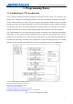
ADT-CNC4620 Programming Manual mode. Call Main program Return Subroutine Fig. 2-1-1 Returning from Subroutine Call Main program Return Subroutine Fig.
ADT-CNC4620 Programming Manual The system can call nine layers subroutine, i.e. a subroutine can call other subroutines (as shown in the figure below) Fig. 2-1-3 Program Nesting Calling 2.1.3. Principal axis control M03, M04, M05 Instruction function: M03 or M3: Principal axis forward rotation; M04 or M4: Principal axis reverse rotation; M05 orM5: Principal axis stop M05 output is valid when the system is electrified, and executes M03 or M04 at this moment.
ADT-CNC4620 Programming Manual cooling pump closes. Coolant control port is determined by #075 port parameter, and the initialized value is OUT4. Note 1: when the system is stopped in emergency, cancel M08 output. Note 2: M09 doesn’t have corresponding output signal, and M08 output is canceled when M09 is executed. 2.1.5. Tailstock control M10, M11 Instruction function: M10: tailstock forward.
ADT-CNC4620 Programming Manual 2.1.8. Program pause M00 Instruction format: M00 or M0 Instruction function: after other instructions of current block are executed, the program pauses. Press the cycle start key to run next block. 2.1.9. Program running ends and return to program beginning M30 Instruction format: M30 Instruction function: after other instructions of current block are executed, the program stops automatically, executes M05, M09, and the processing pieces increase by 1.
ADT-CNC4620 Programming Manual Gear position control: S _1~16 principal axis rotation is controlled by switching 16-gear BCD code. In gear position control mode, #061 comprehensive parameter must be 1, and port parameters #070~073 specify the output port of gear position. Analog control: S _0~maximum rotation; in analog control mode, #061 comprehensive parameter must be 0, and it is required to set the maximum principal axis rotation of parameter #20.
ADT-CNC4620 Programming Manual the principal axis ratio adjustment key. In the main menu of the controller, you can press the left/right key to modify the ratio, or use the principal axis ratio knob on the additional panel to modify principal axis ration; to modify with the left/right key, the principal axis should be started first. The actual rotation after the principal axis ratio is adjusted is limited by the maximum rotation of the current gear position of the principal axis.
ADT-CNC4620 Programming Manual fixed linear or arc track. This system allows G instruction and manual fast moving; X axis direction and Z axis direction can’t move simultaneously in manual fast moving. The fast moving speeds of X axis and Z axis are set by X axis fast moving speed and Z axis fast moving speed respectively. You can adjust the actual fast moving speed with the ratio adjustment key, and the actual fast moving speed is 25%, 50% or 100% of the set fast moving speed.
ADT-CNC4620 Programming Manual Fig. 2-4-1 The program follows: O0010; G00 X160 Z80; (move the machine tool to safe position first) G98; G0 X50 Z0; (move to point B quickly from point A through point M) G1 W-30 F250; (B→C) X100 W-20; (C→D) X140; (D→E) G2 W-40 R20; (EFG arc interpolation) W-10; (G→H) M30; % 2.4.3.
ADT-CNC4620 Programming Manual 2.4.4. Manual feeding Manual feeding: this system allows X axis or Z axis positive/negative motion at current manual feeding speed in the manual mode, X axis and Z axis can’t move simultaneously. The actual manual speeds in X axis direction and Z axis direction are adjusted with the manual ratio adjustment key in the range 10%~150%.
ADT-CNC4620 Programming Manual i.e. one tool can correspond to several offset No. The tool offset corresponding to tool offset No. 00 is X=0, Z=0, and the system doesn’t have tool compensation state, i.e. coordinate offset of the system is 0 (without coordinate offset). After tool length compensation, execute T□□00, the system will offset the system coordinates reversely according to current tool offset, the state is changed from tool length compensated to not compensated, the displayed tool offset No.
ADT-CNC4620 Programming Manual 3. G Instruction 3.1. Introduction G instruction consists of instruction address G and later 1~2 instruction values. It is used to regulate the interpolation mode, pause function and coordinate setting of the tool relative to the workpiece. G □□ Instruction value (00~99, first 0 can be omitted) Instruction address G G instruction word is divided into group 00, 01, 02, 03, and 04. In the same block, you can enter G instruction words of different groups.
ADT-CNC4620 Programming Manual G03 Arc interpolation (CCW) G32 Thread cutting G90 Axial cutting cycle G33 Z axis taping cycle G92 Thread cutting cycle G94 Radial cutting cycle G04 Pause, quasi stop G31 Jump instruction G27 Reference point returns checking instruction G28 Return to mechanical home G29 Return instruction from the reference point G30 00 Return to second reference point instruction G50 Coordimate system setting G70 Finishing cycle G71 Axis roughing cycle G72 Radi
ADT-CNC4620 Programming Manual reach the end point at the same time. Either or both instruction addresses X(U) and Z(W) can be omitted. If one is omitted, the coordinates of the start point and end point of the axis are consistent; if both are omitted, the start point and end point are in the same position.
ADT-CNC4620 Programming Manual End point Start point 3.2.3. Arc interpolation G03, G02 Instruction format: G03/ G02 X(U)_ Z(W)_ R_ (I_ K_) F_; Instruction function: the motion track is the CW arc/CCW arc from the start point to the end point, and the track is shown in the figure below. R: arc radius (0~9999.999mm); I: the difference between X coordinates of the circle center and arc start (-9999.999~9999.999mm); K: the difference between Z coordinates of the circle center and arc start (-9999.999~9999.
ADT-CNC4620 Programming Manual Start point End point Circle center Fig. 3-2-3-2 Program: G02 X63.06 Z-20.0 R19.26 F300; Or G02 U17.81 W-20.0 R19.26 F300; Or G02 X63.06 Z-20.0 I35.36 K-6.37 F300; Or G02 U17.81 W-20.0 I35.36 K-6.
ADT-CNC4620 Programming Manual in the circle center and arc direction defined by the instruction, X axis and Z axis move along the arc from the start point at the same time; if the coordinates of X axis or Z axis are same to the end point, X axis or Z axis stops motion, and the axis (Z axis or X axis) continues to move to the end point, as shown in Fig. 3-4-4 below End point Start point Fig. 3-4-4 3.2.4.
ADT-CNC4620 Programming Manual simultaneously X: absolute coordinates of center point in X direction; U: the difference of the absolute coordinates of the center point and start point in X direction; Z: absolute coordinates of center point in Z direction; W: the difference of the absolute coordinates of the center point and start point in Z direction.
ADT-CNC4620 Programming Manual automatically for calculation; if X is short axis, V is the radius. Instruction function: the motion track of the tool is a straight line from the start point to the end point; the coordinate axis with larger displacement from the start point to the end point (X axis depends on the radius value) is the long axis, and the other is the short axis.
ADT-CNC4620 Programming Manual receives the signals from principal axis encoder Z (origin), it moves X axis or Z axis and starts thread processing, therefore, the processing of same thread can be finished through roughing and finishing as long as the principal axis rotation isn’t changed.
ADT-CNC4620 Programming Manual immediately. 3.3.2. Z axis taping cycle G33 Instruction format: G33 Z(W)__ F__; Instruction function: the motion track of the tool is from the start point to the end point, and then returns to the start point.
ADT-CNC4620 Programming Manual X: new X axis absolute coordinates of current position; Z: new Z axis absolute coordinates of current position; Instruction function: set the absolute coordinates of current position, and thus create workpiece coordinate system (also floating coordinate system). After executing this instruction, the system sets current position as the program home.
ADT-CNC4620 Programming Manual 3.5.1. Axial cutting cycle G90 Format: G90 X/U Z/W R_ F_ ; X/U: cutting end X axis coordinates; Z/W: cutting end Z axis coordinates; F: cutting speed R: cone slope; radial coordinate difference (radius) between cutting start and cutting end; if R and U do not have same sign, |R| ≤ |U/2| (diameter programming) or |R| ≤ |U/2|(radius programming) is required.
ADT-CNC4620 Programming Manual 3) U, W and R reflect the relative position of cutting end and start. G90 has four track combinations depending on the sign.
ADT-CNC4620 Programming Manual O9001 M03 S500T0101 G00 X70 Z2 G90X56Z-60F500 X52 X48 X44 X40 X36 X32 X30 M30 % 3.5.2. Thread cutting cycle G92 Instruction format: G92 X/U Z/W R_ F_ P__ D__ V__; X/U: thread end X axis coordinates; Z/W: thread end Z axis coordinates; F: thread pitch R: thread slope; radial coordinate difference (radius) between cutting start and cutting end; if R and U do not have same sign, |R| ≤ |U/2| (diameter programming) or |R| ≤ |U|(radius programming) is required.
ADT-CNC4620 Programming Manual Thread cutting Quick feeding Z axis X axis Execution process: 1) X axis locates (G0) to cutting start quickly from cycle start; 2) Interpolate to thread end from cutting start; 3) X axis radially back to radial coordinate position of cycle start in quick positioning (G0) mode; 4) Z axis quickly locates (G0) and returns to the start point, and cycle ends.
ADT-CNC4620 Programming Manual G92 thread cutting notice: z The machine tool must be installed with principal axis encoder for thread cutting; the transmission ration of principal axis encoder and the principal axis is 1:1; the principal axis encoder outputs A/B differential signal and Z signal (conversion signal) with 90° phase difference. When cutting thread, the system starts thread processing after receiving principal axis encoder Z signal.
ADT-CNC4620 Programming Manual 3.5.3. Radial cutting cycle G94 Instruction format: G94 X/U Z/W R_ F_ ; X/U: cutting end X axis coordinates; Z/W: cutting end Z axis coordinates; F: cutting speed R: cone slope; axial coordinate difference between cutting start and cutting end; if R and W do not have same sign, |R| ≤ |W| is required.
ADT-CNC4620 Programming Manual If R and W do not have same sign and |R| > |W|, 0792-G90, G92, G94 program error alarms, and the value of R exceeds allowed range 4) During first tool cutting, if W is 0, current value is the end coordinates by default; U can’t be 0, or else the system alarms 5) Before executing G94, specify the position of start point, or else the system takes current point as the start 6) G94 is valid in MDI mode, and modal function is also available. 3.5.4.
ADT-CNC4620 Programming Manual X206.0 Z20.0 (repeat G90 once) … 3) If the fixed cycle instruction is in the same block as M, S and T instructions, the cycle instruction can be executed at the same time with M, S and T instructions. However, if the fixed cycle is canceled (due to instruction G00, G01) after instruction M, S, T as in the example below, the fixed cycle instruction must be re-specified. (For example) N003 T0101; … N010 G90 X20.0 Z10.0 F2000; N011 G00 T0202; N012 G90 X20.5 Z10.0; 3.6.
ADT-CNC4620 Programming Manual 3.6.1.
ADT-CNC4620 Programming Manual An→Bn, Cn→Dn→A’: fast moving Bn→Cn: linear interpolation ⑤ The last roughing cycle: A’→B’→C’→ initial point A’→B’: fast moving B’→C’: interpolation depends on the mode specified by ns→nf block. Interpolation speed specifies F value or the F value in ns→nf block according to G71 block, and uses current default F value if not specified. C’→ Initial point: fast moving. G71 roughing cycle ends. Function description: 1) ns-nf block must follow G71 block.
ADT-CNC4620 Programming Manual B: block line ns B’-C’: offset path C: block line nf Related parameters and notice: 1) If ∆d is 0 or larger than total cutting amount, the system alarms. The tool retreating angle is 45°, and do not retreat if R (e) is 0. 2) If △u is 0, X axis doesn’t reserve for finishing; if △u is larger than △d, the system alarms because it can’t calculate the first roughing end. 3) If △w is 0, Z axis doesn’t reserve for finishing.
ADT-CNC4620 Programming Manual M03 S500T0101 G00 X25Z10 M03S550F3000 G71U0.5R0.5 G71P10Q20U0.2W0.2 N10G0X0Z0F300 G2X5Z-2.5R2.5F200 G1W-1.25F300 G2X10W-2.5R2.5F200 G1W-2.5F300 N20X15W-2.5 G70P10Q20 G0X20 Z0 M30 % 3.6.2.
ADT-CNC4620 Programming Manual Finishing track Cutting feeding A-B-C: program path Fast moving A: roughing reference point Initial point Execution process: ① Initial point → A1: fast moving; ② First roughing cycle: A1→B1→C1→D1→A2 A1→B1, C1→D1→A2: fast moving B1→C1: linear interpolation ③ Second roughing cycle: A2→B2→C2→D2→An A2→B2, C2→D2→An: fast moving B2→C2: linear interpolation ④ The nth roughing cycle: An→Bn→Cn→Dn→A’ An→Bn, Cn→Dn→A’: fast moving Bn→Cn: linear interpolation ⑤ The last roughing cycle:
ADT-CNC4620 Programming Manual 4) If the combined cycle instruction should be used several times in the same program, ns~nf can’t have same block No., or else the ns~nf profile may have error when the next combined cycle instruction is executed. 5) If the last tool feed is smaller than U(△d), the system will execute the last roughing cycle directly 6) Tool retreating path: after last roughing, the tool directly retreats to the initial point from point nf.
ADT-CNC4620 Programming Manual B: block line ns B’-C’: offset path C: block line nf Related parameters and notice: 1) If ∆d is 0 or larger than total cutting amount, the system alarms. 2) The tool retreating angle is 45°, and do not retreat if R (e) is 0. 3) If △u is 0, X axis doesn’t reserve for finishing. 4) If △w is 0, Z axis doesn’t reserve for finishing; if △w is larger than △d, the system alarms.
ADT-CNC4620 Programming Manual O7201 M03S500T0101 G00X20Z5 M03S500F3000 G72W0.5R-0.4 G72Q20U0.2W0.2 N10G1X17Z-11.25F300 X15 W5 G1X10W2.5F200 G1W2.5F300 G02X5W2.5R2.5F200 G1W1.25F300 N20G2X0W2.5R2.5F200 G70P10Q20 G0X20 Z5 M30 % 3.6.3. Closed cutting cycle G73 Instruction format: G73 U(△i) W(△k) R(d) F_ S_ T_ G73 P(ns) Q(nf) U(△u) W(△w) U(△i): X axis roughing reserve. Unsigned, negative sign is invalid (radius) W(△k): Z axis roughing reserve.
ADT-CNC4620 Programming Manual Finishing track(program path) Fast moving Cutting feeding A-B-C: program path Execution process: ① A→A1: fast moving; ② First roughing cycle: A1→B1→C1→A2: A1→B1→C1: interpolation depends on the mode specified by ns→nf block. The interpolation speed specifies F value according to G73 block, and uses current default F value if not specified. C1→A2: fast moving ③ Second roughing cycle: A2→B2→C2→A3 A2→B2→C2: interpolation depends on the mode specified by ns→nf block.
ADT-CNC4620 Programming Manual 6) Before executing G73, the tool must specify the position of the initial point first, which must be out of the program path limit range, or else the system alarms. If the position of the initial point isn’t specified, the current point is the initial point.
ADT-CNC4620 Programming Manual B: block line ns B’-C’: offset path C: block line nf Related parameters and notice: 1) △i can be set with parameter (116-G73 X axis margin), or modify parameter setting with program instruction; if △i is smaller than △u, the system alarms. 2) △k can be set with parameter (117-G73 Z axis margin), or modify parameter setting with program instruction; if △k is smaller than △w, the system alarms.
ADT-CNC4620 Programming Manual G73 processing example programming Fig. 3-11-8 O7301 M03S500T0101 G00X25Z5 G73U5W5R5F500 G73P10Q20U0.2W0.2 N10G0X1Z-0.5R0.5F300 X5Z-5 X10 Z-10 G03X15W-2.5R2.5 G1Z-15 N20G2X20W-2.5R2.
ADT-CNC4620 Programming Manual 3.6.4. Finishing cycle G70 Instruction format:G70 P(ns) Q(nf); P(ns): the number of the first block of the finishing track; Q(nf): the number of the last block of the finishing track; Instruction function: the tool starts finishing from the start position along the workpiece finishing track specified by ns~nf block. After G71, G72 or G73 roughing, finish with G70 instruction, and complete the cutting of finishing margin in one time.
ADT-CNC4620 Programming Manual P(Δi): single radial (X axis) offset of the tool, radius, unsigned. Offset direction is same to the radial direction of the end coordinates. Q(Δk): single axial (Z axis) feeding of the tool, unsigned. Feeding direction is same to the axial direction of the end coordinates. R(Δd): radial (X axis) tool retreating after cutting to the groove bottom, unsigned. The retreating direction is opposite to the radial offset direction.
ADT-CNC4620 Programming Manual A1 start B1 end point Related parameters and notice: 1) If e is 0, the system doesn’t have axial tool retreating action. 2) The system alarms if Z/W isn’t specified or the movement is 0. 3) The system alarms if X/U is specified but P(Δi) is larger than X axis movement (U/2). If P(Δi) is specified to 0, it can be used for axial cycle drilling. 4) If Δk is 0 or larger than entire groove depth (W), the system reports error.
ADT-CNC4620 Programming Manual 3.6.6. Radial grooving multi-cycle G75 Instruction format: G75 R(e ) ; G75 X/U _ Z/W_ P(Δi) Q(Δk) R(Δd) F_ ; R(e ): radial (X axis) tool retreating, radius, unsigned X/U: groove end coordinates (X is absolute coordinates, and U is the increment from current coordinates to point coordinates) Z/W: groove end coordinates (Z is absolute coordinates and W is the increment from current coordinates to point coordinates) P(Δi): single radial tool feeding, unsigned, radius.
ADT-CNC4620 Programming Manual Function description: 1) The position of thee cutting start (A1) should be specified before grooving cycle, or else the system takes current point as the cutting start. 2) In the first grooving cycle, the tool isn’t retreated in axial direction when cut to the groove bottom (B1) 3) If Z/W isn’t specified or movement is 0, the system considers Q(Δk) as 0 no matter whether Q(Δk) is specified.
ADT-CNC4620 Programming Manual 4. CNC Process Knowledge 1. What is the content of CNC programming? A: Analyze part drawing, determine process and path, calculate the coordinates of tool track, write processing program, enter programs into CNC system, check the program, cut for testing, etc. 2.
ADT-CNC4620 Programming Manual processing allows using the machine tool reasonably, making the distortion and error produced in roughing be modified in finishing, to improve processing precision; in addition, it also finding crack, pore and other defects in advance and stop the processing in time. 8.
ADT-CNC4620 Programming Manual 1) Select appropriate tool material with good cutting performance; 2) Select reasonable tool geometric parameters; 3) Use proper cutting liquid; 4) Select reasonable cutting amount. 5) 16. What are the advantages of using indexable carbide blade? A: Have the following advantages: 1) Since the blade isn’t welded and doesn’t require grinding during usage, it will avoid internal stress and crack due to welding and grinding and improve the tool durability.
ADT-CNC4620 Programming Manual 22. What are the influences of cutting amount on cutting temperature? A: If cutting speed increases by one time, the cutting temperature increases about 30%-40%; if the feeding amount increases by one time, the cutting temperature only increases 15%-20%; if the cutting depth increases by one time, the cutting temperature only increases 5%-8%. 23.
ADT-CNC4620 Programming Manual A: Geometric accuracy of the machine tool refers to the geometric shape accuracy of the basic parts of the machine tool, geometric accuracy of relative position, and geometric accuracy of the relative motion. The work precision of the machine tool is the precision of the machine tool in motion state and under the effect of the cutting force. The precision of the machine tool in work state is reflected on the precision of the processed parts. 32.