
Programming instructions


ADT-CNC4620 Programming Manual
- 2 -
1.2. Definition of coordinate axis
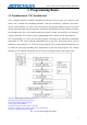
CNC machine tool is shown in Fig. 1-2-1
Tailstock seat Principal axis seat Tool Too holder
Fig. 1-2-1
The system uses the right angle coordinate system constituted with X axis and Z axis. X axis is
vertical to the principal axis, and Z axis is parallel to the principal axis. The direction to the
workpiece is negative, and the direction from the workpiece is positive.
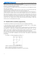
According to the relative position of the tool holder and principal axis of the machine tool, CNC
lathe has front tool holder and rear tool holder. Same programming instruction has different motion
tracks in front tool holder and rear tool holder. This system can be used in the front tool holder and
rear tool holder of the CNC lathe. Seen from the figures below, the X directions of front and rear
tool holder coordinate systems are different, while the Z direction is same. The figures and
examples in this manual use front tool holder coordinate system to describe the application of
programming.
Fig. 1-2-2 Front tool holder coordinate system Fig. 1-2-3 Rear tool holder coordinate system
1.3. Machine tool coordinate system and mechanical home
Machine tool coordinate system is the reference of CNC for coordinate calculation, and is the
intrinsic coordinate system of the machine tool. The origin of the machine tool coordinate system is
mechanical reference or mechanical home.
Mechanical home is determined by the zero switch or home switch on the machine tool, which are
usually installed at the maximum travel in positive direction of X axis and Z axis. For mechanical
home operation, the system will set current machine tool coordinates to 0 after returned to