ADT-HC4500 CNC Flame/Plasma Controller User Manual ADTECH (SHENZHEN) CNC TECHNOLOGY CO., LTD 5th Floor, 27-29th Building, Tianxia IC Industrial Park, Yiyuan road, Nanshan District, Shenzhen Post code: 518052 Tel: 0755-26099116 E-mail: sales02@machine-controller.com Fax: 0755-26722718 http://www.machine-controller.
ADT-HC4500 CNC Flame/Plasma Controller Copyright All property rights of this user manual are reserved by Adtech (Shenzhen) CNC Technology Co., Ltd (ADTECH for short). No institution or person is allowed to counterfeit, copy, transcribe or translate this user manual without permission of ADTECH. This user manual does not include warranty, standpoint expression, or other hints in any form.
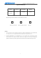
ADT-HC4500 CNC Flame/Plasma Controller Upgrade Information Item No. Version No. Revision Date Remark HC4500 0.1.4 2011/02/24 Edition 4 (General) Note: Meanings of the three numbers in version number are as follows: 0 Library main version No. 1 Library secondary version No. 4 Reserved Remark: 1. This user manual is strictly emended and checked by ADTECH (SHENZHEN) CNC TECHNOLOGY CO., LTD, however, it is not guaranteed that the user manual has no any mistake or error. 2.
ADT-HC4500 CNC Flame/Plasma Controller Safety Notice Read this safety notice before operating. I. Notice 1、 Notice on safety: Original copy of safety notice should be dispensed to every operator. Do not open the controller cover without permission; otherwise, it would be out of the range of guarantee. Cut off the power supply in case the machine is not used for a long time. Pay attention not to drop any dust or iron powder into the controller. Do not pour any liquid into the controller.
ADT-HC4500 CNC Flame/Plasma Controller II. Statement: We offer one year factory warranty or lifetime maintenance for any malfunction arising under the normal use. In case of man-made damage or if the warranty expired, ADTECH will charge a certain cost price of parts. However, the warranty is not applied to the following conditions: The label of serial number is torn down.
ADT-HC4500 CNC Flame/Plasma Controller Content Upgrade Information ..............................................................................................................2 Safety Notice ...........................................................................................................................3 Chapter I. Introduction ..........................................................................................................8 1. Function introduction ....................................
ADT-HC4500 CNC Flame/Plasma Controller 4.3 Adjustment (Adju).........................................................................................................................58 4.4 Control (Ctrl).................................................................................................................................58 4.5 Accuracy (Prec) .............................................................................................................................60 4.6 Save ....................
ADT-HC4500 CNC Flame/Plasma Controller 4.2 Current adjustment of driver .......................................................................................................102 4.3 Test method of impulse equivalent..............................................................................................102 4.4 Anti-interference measures..........................................................................................................102 Chapter VI Troubleshooting..............................
ADT-HC4500 CNC Flame/Plasma Controller Chapter I. Introduction 1. Function introduction HC4500 is a newest generation of high-performance flame/plasma controller developed by ADTECH. The control circuit adopts the ARM9 high-speed microprocessor, large-scale custom-tailor IC chip, and multi-layer PCB, and the display adopts 7” color display screen. Surface mount devices are used throughout the entire process.
ADT-HC4500 CNC Flame/Plasma Controller 22) File name can be displayed in Chinese so that users know clearly the content of files. 23) Users can download the latest upgrade via the USB disk for updating the application. 24) End users can restore the factory default and system files using the one-key backup and restoration function, which better protects the system parameters and system files.
ADT-HC4500 CNC Flame/Plasma Controller Chapter II Quick Start ADT-HC4500 flame/plasma controller can be used in machine tool to control flame or plasma cutting gun for cutting. This system is displayed with window prompt by grade. In the menu of an interface, you can press [F1] to [F6] to select the relevant functions, or press [ ] or [ ] to return to the previous menu. This chapter introduces the general operating procedures for using the system, allowing users to be able to use quickly.
ADT-HC4500 CNC Flame/Plasma Controller Main menu →Press [F6] to enter the upgrade interface →Press [F6] (Help) to search for the relevant help information. 2. Restore factory default In case there is a condition of abnormal speed or accuracy due to the improper adjustment of system parameters, you can, in main menu of system, press [F6] (Upgd) →Press [F1] (LEV)→Press [F1] (LEV)→Press [ENTER] to restore the parameters to factory default.
ADT-HC4500 CNC Flame/Plasma Controller Picture 2.3 Figure library interface Operation: Press [X+], [X-], [Y+], or [Y-] to move the cursor up, down, left or right. Press [S↑], [S↓] to page up or down, and press [ENTER] to enter the figure. 4. Copying processing files Insert the USB disk with copied processing files into the USB port of control system. In main menu, press [F3] (Edit) →[F3] (Udsk).
ADT-HC4500 CNC Flame/Plasma Controller interface. 5. Calling in processing file In main interface, press [F3] → [F2] to enter the interface for calling in files as follows: Picture 2.5 File calling interface After entering the above interface, press [Y+] or [Y-] to select the processing file, and then press [F2] or [ENTER] to confirm and enter the processing code editing interface.
ADT-HC4500 CNC Flame/Plasma Controller 2.6.1 Speed setting interface First, set the processing speed in the interface as above picture. The speed is the max speed that the actual processing can achieve. Press [X+], [X-], [Y+], or [Y-] to move the cursor to make the selection, and then press the number key on left of panel to input the value. After setting the speed, press to return to main menu. Press [F1] again to enter the auto processing interface: 2.6.
ADT-HC4500 CNC Flame/Plasma Controller Processing speed is determined by the “CutSpeed” in speed setting interface and the “Speed” rate in auto processing interface. Actual Processing Speed =CutSpeed × Speed Rate Note: Speed rate can be adjusted by pressing [F↑] and [F↓] on the panel, or just the [F] key. 7. Adjustment of Manual Speed In main interface, press [F4] (Para) → [F2] (Speed) to enter the speed setting interface. See section “HSpeed” for the interface picture.
ADT-HC4500 CNC Flame/Plasma Controller circular arc shape. The system acceleration and deceleration are set as follows: Press [F4] (Para) in main menu interface, and press [F2] (Speed), then, set the speed in “StrSpeed” and “AddSpeed” (See picture below). Detailed definitions are as follows: 2.8 Speed settings 1. [StrSpeed]--Start-up speed: Track-Move, a speed of starting up. For example, if the “StrSpeed” is set to be 300, the system speed is 0.3m at the just beginning.
ADT-HC4500 CNC Flame/Plasma Controller 2. [AddSpeed]-- Acceleration: It is an average increment of increasing the processing speed from start-up speed to the highest speed. For example, if the start-up speed is 300, acceleration is 100, and highest speed is 1000, then, the speed is increased to 300, 400, 500…1000 at 100 intervals; if the acceleration is 50, then, the speed is increased by 50 each time. The acceleration is determined by the Precision (In main menu, press [F4] (Para) → [F5] (Prec).
ADT-HC4500 CNC Flame/Plasma Controller 2.9.1 Control interface In auto cutting interface, it will carry out preheating before perforating. Total preheating time and the current preheating time will be shown on the right bottom of the interface; on the left bottom there will show “Record & GO, Press [G]; Stop, press [START]; Go-on, Press [STOP].” As prompted, if you press [START], the system will stop preheating immediately and go to the next action without saving the preheating time.
ADT-HC4500 CNC Flame/Plasma Controller 10. Power Failure Treatment In order to avoid the waste of raw materials caused by the sudden power failure, the system equips with a power-off protection function. If the device is powered off during the processing, the system will automatically save the last processing track as a break point.
ADT-HC4500 CNC Flame/Plasma Controller 2.12 Change of cutting gun nozzle FBack and Cutting : Go back to the interrupt with no cut then cut continue the program. FBack and Stop : Go back to the interrupt with no cut then stop program.. CBack and Cutting : Go back to the interrupt with cutting then then cut continue program. Process ringht here : cut continue program right here. 13.
ADT-HC4500 CNC Flame/Plasma Controller 14. Movement of work piece Work piece 2 Work piece 2 Work piece 1 Work piece 1 Picture 1 Picture 2 To save the steels during the processing, you can move the tracks of work piece to a certain place for processing when cutting some kinds of figures. As shown in above pictures, the out frame is the steel plate, and the inside frame is the figure to be cut.
ADT-HC4500 CNC Flame/Plasma Controller Picture 2.15.1 Positioning mode of line selection Direct change coordinate: the cutting gun does not move, but the coordinate is changed to the coordinate of this line directly. Auto move Gun: the cutting gun moves from the current position to the coordinate of selected program line. You can press [Y+] or [Y-] to change the mode of positioning when selecting line, and press [ENTER] to select the line number (as Picture 2.15.2 shown below).
ADT-HC4500 CNC Flame/Plasma Controller Picture 2.16.1 before arraying (Processing interface) The acquiescent deviant is the space usage size as aboce picture, which it means the single graph height and width. Suitable adjust the width and height can make the arraying more reasonable. Press the No. key input the parameter value, press 【Y+】、 【Y-】select item of paramters, input correct parameter, press 【Confirm】 enter into the direction seletion of arraying.
ADT-HC4500 CNC Flame/Plasma Controller Picture 2.16.3 After array graph Matters need attention when you operate arraying 1) After the array, it will not save the original process file, like stop coordinate etc. 2) After Array, press 【Retn】enter into dealing interface, It can check if the size suitable the plate or not. Afresh Array press 【F6】(restore) 17.
ADT-HC4500 CNC Flame/Plasma Controller Picture 2.17.1 Before X mirroring Picture 2.17.2 After X mirroring 18. Rotation Sometimes, the position and angle of the steel plate are required to meet the XY axis of the cutting machine during the cutting. However, in the actual processing, it is hard to avoid the XY axes on steel plate deviating from the XY axes of cutting machine for an angle.
ADT-HC4500 CNC Flame/Plasma Controller Picture 2.18 Rotation 19. Calibration If rotation angle is uncertain when calibrating the steel plate, we can get a correct rotation angle by calibration function. First, a reference axis is required, around which the figure is rotated at a certain angle when calibrating.
ADT-HC4500 CNC Flame/Plasma Controller and the X axis of reference coordinate. Reference axis Y: the offset angle of steel plate is the angle formed by Y axis of steel plate and the Y axis of reference coordinate. Press 【X+】【X-】【Y+】【Y-】to select the move cutting gun, at the same time, the system will calculate the angel automationly. The following calibration takes X axis as the reference axis.
ADT-HC4500 CNC Flame/Plasma Controller Way of calibrating the steel plate: Original position 1) Position after the move As above picture, point A is the start point of cutting gun. You can figure out the slope angle of the steel plate by moving the cutting gun to any point of its base line. Press [X+] → [Y-], or [Y-] → [X+]; then, press [ENTER] to confirm. 2) Then, the figure displayed on the controller will be rotated at a certain degree.
ADT-HC4500 CNC Flame/Plasma Controller Press [X+] → [Y+], or [Y+] → [X+], then, press [ENTER] to confirm. The position of figure to be processed and the steel plate is shown as follows: 20.Tool Setting Main Interface after power on, press【F1】Auto---【 F4】Graph, Enter into Graph track follow interface, Press key 【G】.
ADT-HC4500 CNC Flame/Plasma Controller Chapter III Operations and Details 1. Auto In main interface, press [F1] (Auto) to enter the auto processing interface as follows: Picture 3.1 ① Flame mode Picture 3.
ADT-HC4500 CNC Flame/Plasma Controller Picture 3.
ADT-HC4500 CNC Flame/Plasma Controller Picture 3.1.1 Pause in auto mode Processing in pause (displacement perforating and gun changing) Picture 3.1.1.2 Pause processing During the cutting, if [Pause] is pressed, according to whether the cutting gun has been moved manually, there are the following treatments: 1) If there is no manual movement after the pause, the controller will start perforating once you press the [Start] button, and then proceed running the program.
ADT-HC4500 CNC Flame/Plasma Controller cycle, and then runs the processing program. [2]. the controller travels back to where the processing program pauses, and then stops. [3]. the controller enables the cutting at current position, and then returns to where the processing program pauses and runs the processing program. The three options can be selected by pressing [Y+] or [Y-] to move “←” up and down. After that, press [ENTER] to run the relevant function. [4].
ADT-HC4500 CNC Flame/Plasma Controller Picture 3.1.2.2 Manual interface in flame mode Picture 3.1.2.2 Manual interface in plasma mode 1.2.2.1 Inching In manual interface as Picture 3.1.2.2, press [F1] (Point), and the above interface will show up when the “Inching” is highlighted, with an input prompt “Input L value” at the bottom of the screen. Press the number keys to input the length of inching, unit in mm.
ADT-HC4500 CNC Flame/Plasma Controller Picture 3.1.2.2.1 Inching setting interface If “Inching” is not highlighted, it is default that once [X+], [X-], [Y+], or [Y-] is released, all axes are doing continuous motion until these keys are pressed again or the [Stop] key is pressed when the system will decrease and stop moving. If you press [G] key, the system will be switched between manual and inching.
ADT-HC4500 CNC Flame/Plasma Controller Picture 3.1.2.2.2 Breakpoint interface It is the same as [F6] (spot) in auto interface, please refer to “Breakpoint” in 1.27 in this chapter. 1.2.2.3 Clear In manual interface, you can press [F5] to clear the parameter in counting. If you press [X] or [Y] → [F5] (Clear) → [ENTER], it is to clear the entire line of X and Y coordinates. To clear the last digit of value, you can just press [DEL] on the panel. 1.2.2.
ADT-HC4500 CNC Flame/Plasma Controller move forward at actual processing speed without running M switching instruction, which is equal to traveling at processing speed. 1.2.5. Figure processing (Pro) In figure interface as Picture 3.1.2.5 above, → you can press [F4] (Pro) to enter the figure processing interface as follows: Picture 3.1.2.5.1 Interface of figure processing 1.2.5.1.1 Rotation (Turn) In above processing interface, press [F1] (Turn) to enter the rotation interface.
ADT-HC4500 CNC Flame/Plasma Controller Picture 3.1.2.5.1.1 Interface of figure processing 1.2.5.1.2. X, Y mirror See “Mirror” in section 17 of chapter II. 1.2.5. 1.3 Rotation (Whir) See “Calibration” in section 18 of Chapter II. 1.2.5. 1.4 Calibration See “Calibration” in section 19 of Chapter II. 1.2.5. 1.5 Restoration In rotation interface, you can press [F6] to restore the current figure to figure before mirroring, rotating or calibrating. 1.2.5.1.
ADT-HC4500 CNC Flame/Plasma Controller Direct change coordinate refers to that the cutting gun does not move but the coordinate is changed to the coordinate of perforating point directly. Auto move gun refers to that the cutting gun is moved from current position to perforating point. After that, select any M07 perforating point during the figure processing to process, and input the perforating point and press [ENTER].
ADT-HC4500 CNC Flame/Plasma Controller In case of manual pause in auto processing, when you press [F6] (breakpoint), the system will save the current working track (current position of cutting gun) as a breakpoint automatically. This breakpoint is saved permanently. When you restart the machine or re-enter the auto mode, as long as the current program is not changed, you can press [F6] (Breakpoint) to restore based on the breakpoint.
ADT-HC4500 CNC Flame/Plasma Controller 4) [F] key allows you to switch the speed ratio swiftly. Press [F] key if the ratio is between 50%--100%, the speed ratio will be switched to 5%; and if the ratio is between 1%--50% when you press [F], the speed ratio will be switched to 80%. 5)Figure interface operation: You can press the number key to enlarge the figure. 0 –: resume the figure to original state; 1- Zoom in×1, 2- zoom in×2… and so on.
ADT-HC4500 CNC Flame/Plasma Controller Picture 2.2 User can get the difference process graph based on the parameter setting. Parts Type: Hole-cutting and slicing. Related workpiece in the inner of graph when slicing; Related workpiece in the outside of the graph when hole-cutting. Lead in/out Line: Lead-in line (arc) is a reserved lead line (Arc) for avoided to over-burnning of point in the cross the hole.
ADT-HC4500 CNC Flame/Plasma Controller the code of file being processed. The code can be viewed only, and cannot be edited. If there is more than one page, you can press [pgup↑] or [pgdn↓] to page up or down. Picture 3.1 Window of editing function menu3.1 Explanation of sub-menu 3.1.1 New Picture 3.1.1 Interface of creating new file In editing interface as Picture 3.1, press [F1] to enter the interface of creating new file as Picture 3.1.
ADT-HC4500 CNC Flame/Plasma Controller Operations of Pinyin input are as follows: 1. Press [ENTER] to select the current character 2. Press [ESC] to delete all the input characters 3. Press [shift] to change the input method 4. Press [DEL] to delete the last character 5. Press [Y+], or [Y-] to select the previous or next character 6. Press [X+] or [X-] to page up or down the listed characters 7. Letters on panel are defined as: Press [ENTER] key after the input.
ADT-HC4500 CNC Flame/Plasma Controller Picture 3.1.1.2 Interface for prompting the exist of input file name In this prompt interface, you can press [ENTER] to cover the original file and enter the interface as Picture 3.1.1.2; otherwise, press [ESC] to exit to interface as Picture 3.1.1. Picture 3.1.1.3 Interface of editing new file Once a new processing file is created, you can edit the required code of processing file in editing area. For detailed editing of code, see “3.2 Editing processing file”.
ADT-HC4500 CNC Flame/Plasma Controller 3.1.2 Load 1) In window of editing function menu as Picture 3.1, press [F2] to enter the file loading interface as follows: Picture 3.1.2 File loading interfaceAfter entering into the above interface, press [F↑] or [F↓] to select the processing file, and press [F2] or [ENTER] to select, and then enter the processing code editing interface. For file edition, see “3.2 Editing processing file”. 2) [INS] key: Enable the help system of the current interface. 3.1.2.
ADT-HC4500 CNC Flame/Plasma Controller Picture 3.1.2.1 File copy function 3.1.2.2 Delete In processing file loading interface, you can choose to delete files in system catalog. When deleting the processing file, the system will ask whether to delete, you can press [ENTER] to delete or [ESC] not to delete . Picture 3.1.2.
ADT-HC4500 CNC Flame/Plasma Controller 3.1.3 USB disk In interface as Picture 3.1, press [F3] to enable the USB disk connecting function. If the USB disk is not connected well or if the format of USB disk is not compatible with the system, the following interface will show up: Picture 3.1.3 USB disk is not connected If the USB disk is connected, the interface will show the name of file stored in the USB disk, as the following picture shows: Picture 3.1.3.
ADT-HC4500 CNC Flame/Plasma Controller (Copy) or [ENTER]. After the copy, the system will pop up a prompt “Data are completely copied, press any key to return”, you can then press any key to exit. 3.1.4 Define 3.1.4 Definition interface As Picture 3.1 shows, in editing interface, press [F4] (Define) to enter the definition interface. 3) In this interface, press [F1] to define the M07 instruction.
ADT-HC4500 CNC Flame/Plasma Controller c Arcing, arcing delay M12 d Perforating, perforating delay Start the following actions Users can define the functions of M07 as required. 4) [F2] is used to define the M08 instruction.
ADT-HC4500 CNC Flame/Plasma Controller Picture 3.2 Processing file editing interface 3.2.1 Figure In processing file editing interface as above, Press [F1] and the interface will show the preview figure you are editing for your reference. 3.2.2 Test In processing file editing interface as Picture 3.2, after enter the code of processing file or loading the code of nest software, you can press [F2] to detect whether the code of processing file has error.
ADT-HC4500 CNC Flame/Plasma Controller Picture 3.2.1.2 Error code detection interface In case of the interface as above picture, press [ENTER] and the cursor will stop at the error code line, and you can then modify the error character line. After the modification, you can press [F2] to test the processing file, while the system will pop up the following dialogue box: Picture 3.2.1.2.
ADT-HC4500 CNC Flame/Plasma Controller 3.2.3 Save 3.2.1.3 Saving file When the processing code is entered or the code is tested, you should press [F3] to save it before exiting the interface; otherwise, the system cannot memorize the current processing file. Press [F3] and the system will ask whether to save as other file (as Picture 3.2.1.3). If you press CANCEL], the system will cover the original file. If you press [ENTER], the system will ask you to input the file name.
ADT-HC4500 CNC Flame/Plasma Controller 4. Parameter In main interface, press [F4] to enter the parameter setting function, and the options are as follows: Picture 4 System parameter setting interface 4.1 System In system parameter setting interface as above, press [F1] to enter the system parameter setting interface: Picture 4.
ADT-HC4500 CNC Flame/Plasma Controller default or user-defined mode. For definition, see “Definition” in section 3. Language: Choose the language. The system supports operating interface of many languages. Machine: Two cutting processes are provided, flame cutting or plasma cutting. Theunit(Metric/Imperial): It is only available before entering into the auto mode or testing the program.
ADT-HC4500 CNC Flame/Plasma Controller 4.1. 2 Flame Step Torch Height Press 【F4】flame in the config parameter setting interface, enter flame step torch height parater setting interface: press figure input parameter value, Press 【Y+】【Y-】select parameter. Picture 4.1.2 Flame step Torch Height Parameters Details: 1) Z axis Torch height allow: When Status “Open”, Flame cutting of system can accept Z axis make the gun make adjustment of height 2) Z axis pulse equivalent: Z Axis setting of precision, See 4.5.
ADT-HC4500 CNC Flame/Plasma Controller picture, when you can set all the speed parameters including speed, hand speed and acceleration or deceleration. Picture 4.2 Speed parameter settings 4.2.
ADT-HC4500 CNC Flame/Plasma Controller 4.3 Adjustment (Adju) In system parameter setting interface as Picture 4, press [F3] and the interface will become as the following picture, when you can set the limit coordinate, origin coordinate, and backlash. Picture 4.3Adjusting parameter settings 4.3.
ADT-HC4500 CNC Flame/Plasma Controller Picture 4.4.1 ① Flame Picture 4.4.2 ② Plasma Parameter CutHoleOutside Preheat delay CutGun rising delay Cutgun falling delay Explanation Whether to enable the edge perforating prompt when perforating Preheating time of perforating on the steel plate, which can be adjusted It is usually used before G00 shifting position to lift the cutting gun to a proper height with a purpose of avoiding the collision of cutting gun and steel plat when re-transferring.
ADT-HC4500 CNC Flame/Plasma Controller Ignition delay Holecutgun rises Holecutgun falls Startarcdelay BroeaHole delay InitLocaUp time Slot compensat Hole rise delay (Height)adjusting rate Corner arc rad Corner Drop speed before processing. Due to the gravity action, the falling time of cutting gun is shorter than the rising time.
ADT-HC4500 CNC Flame/Plasma Controller Picture 4.5 Accuracy parameter interface 4.5.1 Pulse equivalent setting 1) In main interface, press [F4] and then [F5] to enter the accuracy setting interface, and set the X and Y pulse equivalent as 0.010000 (at this time, the control system gives a pulse and the motor moves 0.01MM). After the setting, press [F6] to save and exit to the main interface.
ADT-HC4500 CNC Flame/Plasma Controller 4.6 Save You should press [F6] once every time when the value of a submenu in “Parameter” is modified; otherwise, the modified value would not be saved. 5. Diagnosis (Diag) Press [F5] in main interface, and the system will enter the diagnosis interface as Picture 2.6 below: Picture 5 Diagnosis interface 5.1 Sub-menu 1) Diagnosis interface In diagnosis interface as Picture 5, press [F1] to enter the diagnosis testing interface as Picture 5.1.
ADT-HC4500 CNC Flame/Plasma Controller This function can be used to judge whether the input/output port is correct, damaged or normal. Picture 5.1.1 diagnosis testing interface 2)Define backup I/O interface In diagnosis interface as Picture 5, you can press [F2] to show user-defined outlet interface, and press [X+] [X-] [Y+] or [Y-] to set the relevant settings. (As Picture 5.1.
ADT-HC4500 CNC Flame/Plasma Controller ① Flame ② Plasma Picture 5.1.2 User-defined outlet settings 3) In diagnosis interface as Picture 5, Press 【F5】show the currently the upgrade content. 4) In diagnosis interface as Picture 5, you can press [F6] to show the interface of version description, which will show the current version number. Picture 5.1.3 shows the system version number of HC4500.
ADT-HC4500 CNC Flame/Plasma Controller Picture 5.1.3 ① Description of HC4500 version 6. Upgrade (Upgd) Upgrade function is provided for users to upgrade the software to the latest functions. In main interface, press [F6] to enter the system upgrade options interface as picture 6: Picture 6 .1 System upgrade options interface 6.
ADT-HC4500 CNC Flame/Plasma Controller [F2]: Connect the USB disk [F3]: Reserved, not in use for the moment [F4]: Restart the control system [F5]: Connect the computer [F6]: Main help system [INS]: Enable the help system of current interface 6.2 Restoration (Rev) In upgrade interface as Picture 6.1, you can press [F1] to enter the system parameter restoration/storage interface. Picture 6.2.
ADT-HC4500 CNC Flame/Plasma Controller Picture 6.2.2 Parameters cannot be restored Picture 6.2.3 Parameters are restored To save parameters in system parameter restoration/storage interface, it’s required to input the correct password. To not to save the parameters, you can press [ ] or [ ] to exit.
ADT-HC4500 CNC Flame/Plasma Controller Picture 6.2.4 Interface of setting factory default verification After entering the correct password in interface as above, the following interface will show up: Picture 6.2.5 Interface of setting factory default prompt In this interface, press [ENTER] and the system will set the parameters set in “Parameter” options to factory default. After each “restoration”, the parameters will be restored to the previous stored factory default.
ADT-HC4500 CNC Flame/Plasma Controller Picture 6.2.6 Prompt interface after the factory default is set 6.3 Upgraded by USB disk (Udsk) 1) Connection of USB disk fails Picture 6.3.1 Connection of USB disk fails Download the latest program to USB disk, insert the USB disk into USB port, and press [F6] in main interface to enter the upgrade interface, and then press [F2]. If the connection fails, the system will show the interface as Picture . 6.3.
ADT-HC4500 CNC Flame/Plasma Controller Picture 6.3.2 USB disk is connected If USB disk is successfully connected, press [Y+] or [Y-] to move the cursor to “ADTROM.BIN” in the catalog and press [ENTER], the interface will become as follows: Picture 6.3.3 System is upgrading If the selected file is not the type for upgrading, the system will give a prompt, as Picture 6.3.
ADT-HC4500 CNC Flame/Plasma Controller Picture 6.3.4 Upgrade fails If the selected file is correct, after the download of program, the interface will be displayed as: Picture 6.3.5 System upgrade completes At this time, press [F3] to restart and then press [ESC] when having entered the interface for about 1s, or shut the power supply and press and hold [ESC] to connect to the power supply for few seconds to enter interface as Picture 6.3.5.
ADT-HC4500 CNC Flame/Plasma Controller Picture 6.4.1 connect computer USB Line(As below picture) one side connect with computer, another side connect controller, press【F5】 connect computer, press “my computer” in PC, at this price computer like as 256M U disk will display in your computer, press” U disk”, then copy the newest “adtrom.bin” file to “ADT” folder. After the finished the copy, press turn off the power, press【CAN】, power on, press the newest program in BOIS. Details operation see 6.6 part.
ADT-HC4500 CNC Flame/Plasma Controller 6.5 Recording program When you have copied the latest application software to controller, you need to save the software to the controller BIOS so that the controller can operate the software. To do this, you should cut the controller power supply first, press and hold [ESC] key when the controller is restarted. The interface will ask you to input the password as follows: 6.6.
ADT-HC4500 CNC Flame/Plasma Controller Use [↑] or [↓] to move the cursor to “B. BIOS”, and press [ENTER]. Then, move the cursor to “2. Upgrade PRG” with the same method and press [ENTER] again, the system will give a prompt “Do you really want to upgrade the program, Y/N?” press [ENTER] to confirm. After that, the system will prompt the files are found and are refreshing. As the upgrade completes, the system will prompt “Upgrade complete, please restart the machine”.
ADT-HC4500 CNC Flame/Plasma Controller 6.6.4 Password entry interface to BIOS interface Input correct password to enter the following interface. Refer to supplier for the password. 6.6.5 Enter USB disk interface in BIOS Use [↑] or [↓] to move the cursor to “C. U disk”, and press [ENTER]; then, move the cursor to “1. Communication Connecting” with the same method, and press [ENTER]. Return back to the computer and find the system, which is displayed as a disk drive in form of USB disk on the computer.
ADT-HC4500 CNC Flame/Plasma Controller press [ESC] to exit the communication connecting. 6.6.6 Enter the setting interface of BIOS Use [Y+] or [Y-] to move the cursor to “B. Setting BIOS”, press [ENTER]; then, move the cursor to “2. Upgrade PRG” with [X+] or [X-], and press [ENTER] again. The system will give a prompt “Do you really want to upgrade the program, Y/N?” press [ENTER] to confirm. After that, the system will prompt the files are found and are refreshing.
ADT-HC4500 CNC Flame/Plasma Controller Picture 7.1 Help system 8. Multi-language operations ADTLIB figure library: (It is default that the folder ADTLIB includes Chinese and English figure libraries) Name the four Chinese figures in accordance with the S/N as PIC000.bmp, PIC001.bmp, PIC002.bmp, and PIC003.bmp. Name the four English figures in sequence as EPIC000.BMP, EPIC001.BMP, EPIC002.BMP, and EPIC003.BMP; In case of figures in other languages, please name as OPIC000.BMP, OPIC001.BMP, OPIC002.
ADT-HC4500 CNC Flame/Plasma Controller 2. In case of similar Chinese with two Bytes a word, please name it as config2.ini, In case of similar English with one Byte a letter, please name it as config3.INI 3. Translate the content behind “=” in new file to Chinese, while other contents do not change. 4. For any question, please compare the English configuration file of config1 with the Chinese one in folder ADT. Note: 1.
ADT-HC4500 CNC Flame/Plasma Controller Chapter IV Instruction System 1. Explanation of programming symbol Every motion of the CNC processing is done following the due process, every processing program is composed by several instruction segments, each instruction segment is composed by several function words, and each function word should be started with a letter following by the parameter value.
ADT-HC4500 CNC Flame/Plasma Controller As the above picture, if calculated by relative coordinate, the coordinate of the points in picture are as follows: 1. Point A is the origin, the coordinate is (X0, Y0); 2. Point B is (X50, Y50) relative to point A; 3. Point C is (X50, Y50) relative to point B; 4. Point D is Y-50 relative to point C; 5. Point D returns to point B, and the coordinate is X-50; 2.
ADT-HC4500 CNC Flame/Plasma Controller any content following. It works until the next G20 or G21 instruction is detected. 3.3. G00 idle motion This instruction enables you to travel to the appointed position quickly. During the travel, the system moves from the starting point to end point in rectilinear motion at the manual limiting speed. It would not be influenced by the speed rate.
ADT-HC4500 CNC Flame/Plasma Controller M02 For example (G03): G92 X0 Y0 G00 X55 Y55 G03 I35 M02 ●Current position of cutting gun ○Expected position of cutting gun Explanation: I and J are the increment of center at X and Y-axis direction relative to the origin. When you are writing processing files, if you want to write a circle with a diameter of 100MM, to make it simple you can enter :I50 directly. If the circle diameter is 150MM, you can just enter: I75. 3.6.
ADT-HC4500 CNC Flame/Plasma Controller Loop G80 (End mark of loop) For example: 0000 G92 X100 Y100 0001: G22 L10000 ——Cycle starts 0002: G00 X50 Y50 0003: G01 X80 Y80 0004: G80 ——Cycle ends 0005: M02 3.9. G81 workpiece counting This instruction is used by the system to count the total workpiece automatically. Format: G81 For example: 0000 G92 X0 Y0 0001: G22 L3——Cycle starts 0002: G01 X50 Y50 0003: G81——Counting 0004: G80——Cycle ends 0005: M02 3.10.
ADT-HC4500 CNC Flame/Plasma Controller 4. Common M instructions 1) Common M instructions: Users only need to know the functions of M07, M08, and M02 instructions. M07 refers to fixed cycle of preheating and perforating. When the track is processed and come to perform M08, the system will close all related valves. In the end, perform M02 to finish the processing. Detailed functions of codes are as follows: ① M07 Fixed cycle of preheating and perforating, operating sequence is as follows: Flame: 1.
ADT-HC4500 CNC Flame/Plasma Controller 1. Close the cutting oxygen valve; 2. Lift the cutting gun. Plasma: 1. Close striking arc M13 2.
ADT-HC4500 CNC Flame/Plasma Controller Chapter V Hardware 1. Overall dimension Picture 1.1 Front view Picture 2.
ADT-HC4500 CNC Flame/Plasma Controller XS6 digital output XS3 motor XS5 digital input USB communication XS9 serial port Picture 2.1 Rear view Note: the above length is unit in “mm”. 2. System input/output interface 2.1 Back cover XS6 digital output XS3 motor XS5 digital input USB communication 2.2 Specifications Digital input: Channel: 32, all photovoltaic isolation Input voltage: 12-24V DC High level>4.5V Low level<1.
ADT-HC4500 CNC Flame/Plasma Controller Isolation voltage: 2500V DC Counting input: Channel: Main axis ABZ-phase coding input, all photovoltaic isolation Maximum counting frequency: 2MHz Input voltage: 5-24V DC High level >1.5V Low level <1.
ADT-HC4500 CNC Flame/Plasma Controller XS3 1 9 2 10 3 11 4 12 5 13 6 14 7 15 8 XDR+ XDRXPU+ XPUYDR+ YDRYPU+ YPUZDR+ ZDRZPU+ ZPUPU_COM 5V5V- Line S/N Name Function 1 XDR+ X direction signal + 9 XDR- X direction signal - 2 XPU+ X pulse signal + 10 XPU- X pulse signal - 3 YDR+ Y direction signal + 11 YDR- Y direction signal - 4 YPU+ Y pulse signal + 12 YPU- Y pulse signal - 5 ZDR+ Z direction signal + 13 ZDR- Z direction signal - 6 ZPU+ Z pulse signal + 14 ZPU- Z pulse
ADT-HC4500 CNC Flame/Plasma Controller Connection mode of pulse output signal Differential mode: For stepper motor driver with individual pulse and direction input, and most of servo motor driver, it is recommended to use this mode to get the better anti-interference performance. Stepper motor driver Servo motor driver Single-end mode: It is applicable to the earlier stepper motor driver whose pulse and direction anodes are connected together.
ADT-HC4500 CNC Flame/Plasma Controller 2.2.
ADT-HC4500 CNC Flame/Plasma Controller 14 IN10 Y positive limit (>Y+) 15 IN11 Y negative limit (Y-<) 16 IN12 External emergency stop (STP) 17 IN13 External start key (STA) 18 IN14 External handheld box X- positive control (X-) 19 IN15 External handheld box Y- positive control (Y-) 20 IN16 Deceleration control key of external handheld box (SP-) 21 IN17 Gun down control key of external handheld box (DOW) 22 IN18 Forward 23 IN19 Backward 24 +24V Internal 24V+ of controller (do
ADT-HC4500 CNC Flame/Plasma Controller 2.2.
ADT-HC4500 CNC Flame/Plasma Controller 14 OUT8 Cutting Oxygen / Plasma (arcing) control , M12 (Open), M13 (Closed) 15 OUT9 Cutting gun falling control, M16 (Open), M17 (Closed) 16 OUT10 Backu p, M18 (Open), M19 (Closed) 17 OUT11 Flame cutting Preheating oxygen valve control, M24 (Open), M25 (Closed) 18 OUT12 Backup preheating oxygen control, M26 (Open), M27 (Closed) 19 OUT13 Backup Oxygen/arcing cutting control, M32 (Open), M33 (Closed) 20 OUT14 Backup cutting gun falling control, M36 (
ADT-HC4500 CNC Flame/Plasma Controller It is suggested that the supply voltage be < 24V; it is better not to exceed 30V. Positive and negative poles should not be connected reversely and the load should not be in short circuit; otherwise, it may cause unexpected damage. 2.2.
ADT-HC4500 CNC Flame/Plasma Controller Note: IN20 panel-Stop, IN21 panel-Start IN22-Null, IN23-Null 2.2.5 Wiring of SX8 power supply 2.2.6 SX11 standard USB device interface 3. Connection mode of motor 3.
ADT-HC4500 CNC Flame/Plasma Controller The following connecting diagram shows the connection of ADTECH Q2BYG404MA driver and 56BYGH630C stepping motor: Q2BYG404MA driver + PU + DR + 5V DC power of motor self-lock MF V+ 18-40V DC power VAC BC A+ AB+ BW Bl Re Gr Blu 56BYGH630C Stepper motor Ye 97
ADT-HC4500 CNC Flame/Plasma Controller The following connecting diagram shows the connection of ADTECH Q2BYG404MA driver and 56BYGH630EJP stepping motor: Q2BYG404MA driver + PU + DR + 5V DC power of motor self-lock MF V+ 18-40V DC power VAC BC A+ AB+ BW Bl Ye R Or 56BYGH630EJP stepper motor Coff 98
ADT-HC4500 CNC Flame/Plasma Controller The following connecting diagram shows the connection of ADTECH Q2BYG404MA driver and 85BYGH830A stepping motor: Q2BYG404MA driver + PU + DR + 5V DC power of motor self-lock MF V+ 18-40V DC power VAC BC A+ AB+ BYellow Purple R Bl Wh 85BYGH830A Stepper motor Gre Remark: 1) Please adjust the subdivision of driver and the current code switch properly when using. The subdivision of driver is recommended to be 64 subdivisions, and the current to be 1.
ADT-HC4500 CNC Flame/Plasma Controller 3.
ADT-HC4500 CNC Flame/Plasma Controller 3.3 Connection of Panasonic servo motor XS3 plug of controller X-axis Driver XS3 1 9 2 10 3 11 4 12 5 13 6 14 7 15 8 XDR+ XDRXPU+ XPUYDR+ YDRYPU+ YPUZDR+ ZDRZPU+ ZPUPU_COM 5V5V- CN1/F5 SING1 CN1/F6 SING2 CN1/F3 SING1 CN1/F4 SING2 Servo motor 4. Key Points for Installation & Test 4.1 NCS’s Requirement on Impulse Equivalent Value To improve the device precision, it is recommended to adjust the impulse equivalent value of NCS to be 0.004000—0.006000.
ADT-HC4500 CNC Flame/Plasma Controller 3) However, though the impulse equivalent value is adjusted as precise as 0.001000, the processing speed of the system will be slowed down. Therefore, too small an impulse equivalent value is not recommended. 4.2 Current adjustment of driver Please adjust the current following the driver instructions of different factories. If you use equipped stepping driver Q2BYG404MA+56BYGH630C of ADTECH, please adjust the current of driver to be 1.2 times of motor current. 4.
ADT-HC4500 CNC Flame/Plasma Controller 2) A magnetic loop should be used in the input line of NCS 24V power supply. As shown below: Picture 5.5.4 Note: Do not circle the PE port (Ground wire) inside the magnetic loop.
ADT-HC4500 CNC Flame/Plasma Controller Chapter VI Troubleshooting 1. Why the U-disk cannot be read? Answer: If the controller cannot read the U-disk, you can change the “File system” of U-disk on the computer, and then format it. Detailed operations are as follows: Insert the U-disk to the computer → Open “My Computer” → Find the removable U-disk → Right click the mouse → Click “Format (A)” → change the format of “File system” from “FAT32” to “FAT” → Click “Start” to start formatting.
ADT-HC4500 CNC Flame/Plasma Controller If the auto speed is set as 0, the system will have this problem. 8. Why the motor does not work or is similar to death when it is in “Manual” state? Answer: Please check the “Manual speed limit” to see whether it is a proper speed, and check whether percentage of manual processing is too low. If the manual speed is set as 0, the system will have this problem. 9. The processing code has the “Return” instructions.
ADT-HC4500 CNC Flame/Plasma Controller 5) Find out the corresponding backup output pin according to the following list: Serial number Default Pin Backup Pin Ignition 3 7 Preheat oxygen 17 18 Acetylene 1 5 Cutting Oxygen/Arcing 14 19 Cutting gun rising 2 6 Cutting gun falling 15 20 Turning speed ratio(Turn 4 8 up) 6) Weld the default pins of the plug shown in the following picture to the backup pins according to the above corresponding connection.
ADT-HC4500 CNC Flame/Plasma Controller 7) Connect to the power supply after the installation; in the start-up interface, press [F5] (Diagnose) → [F2] (Define), use [Y↑] and [Y↓] to select upwards and downwards, and use [X→], [X←] to select the state, then, press “Save” to change the corresponding port to the backup state. Annex II Illustration of edition and processing Press [F3] key in main interface to enter the edition option interface, where you can press [F1] key to create a new processing file.
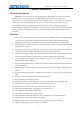
ADT-HC4500 CNC Flame/Plasma Controller 1. Standard circle The program is as follows: Relative coordinates programming and explanation of graph codes: 0000: G92 X0 Y0——set the reference point; 0001: G22 L3——L: set the processing loops; “3” means loop for 3 times; 0002: G41——Left compensation 0003: M07——It is the preheating perforating function. Prompt: Please set all the time parameters in [Control] option in [Parameter] according to the actual demand.
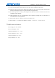
ADT-HC4500 CNC Flame/Plasma Controller 2. Square Relative coordinates programming and explanation of graph codes: 0000: G92 X0 Y0 0001: G41——Left compensation 0002: M07——Perforating; 0003: G01 X50 Y50——Perforation and wire bonding; 0004: Y50——the first side, if the above instruction is G01, this G01 as well as X0 of this instruction cannot omitted for the convenience of editing codes manually.
ADT-HC4500 CNC Flame/Plasma Controller 3.
ADT-HC4500 CNC Flame/Plasma Controller 4.
ADT-HC4500 CNC Flame/Plasma Controller 5.
ADT-HC4500 CNC Flame/Plasma Controller 0018: G2 X-50 Y-50 I-50 J0 0019: G1 X-100 0020: G2 X-50 Y50 I0 J50 0021: G1 Y50 0022: M08 0023: G00 X400 Y50 0024: M07 0025: G2 X100 Y0 I50 J0 0026: Y-100 I0 J-50 0027: X-100 I-50 J0 0028: Y100 I0 J50 0029: G00 X-50 Y-350 0030: G2 X0 Y0 I100 J0 0031: M08 0032: G28 0033: G81 0034: G80 0035: M02 113
ADT-HC4500 CNC Flame/Plasma Controller Annex III G Instruction Quick Reference S/N Name of Instruction Explanation 1 G00 Quick positioning motion (Dry run) 2 G01 Linear processing 3 G02 Clockwise circle processing 4 G03 Anti-clockwise circle processing 5 G04 Pause/Delay 6 G26 X axis returns to reference point 7 G27 Y axis returns to reference point 8 G28 X and Y axes return to reference point at the same time 9 G22 Cycle starts (should be used combining G80) 10 G80 Cycle end
ADT-HC4500 CNC Flame/Plasma Controller Annex IV M Instruction Quick Reference S/N Name of Instruction Explanation 1 M02 Program ends 2 M07 Start the fixed cycle of preheating and perforating 3 M08 Close the fixed cycle of cutting oxygen (plasma arcing) 4 M10/M11 Switch of acetylene valve, M10 (Open), M11 (Closed) 5 M12/M13 6 M14/M15 switch for controlling the rise of cutting gun, M14 (Open), M15 (Closed) 7 M20/M21 ignition switch, M20 (Open), M21 (Closed) 8 M24/M25 switch of prehea