ADT-8840 ADT-8840 Four-Axis Off-Line Motion Control Card User’s Manual ADTECH (SHENZHEN) CNC TECHNOLOGY CO. LTD Add: 5/F, Building 27-29, Tianxia IC Industrial Park, Yiyuan Road, Nanshan District, Shenzhen P.C.: 518052 Tel: 0755-26722719 (20-line) E-mail:Adtech@21cn.com Fax: 0755-26722718 http://www.adtechcn.
ADT-8840 Four-Axis Off-Line Motion Control Card User’s Manual Declaration on Copyright The copyright of all parts in this Manual is reserved by ADTECH (SHENZHEN) CNC TECHNOLOGY CO. LTD (hereinafter referred to as “ADTECH”) and, without permission by ADTECH, nobody shall reproduce, copy, transcribe or translate any part therein. No part of this Manual shall be considered as warranty, expression of standpoint or other implications in any form whatsoever.
Contents Chapter I Overview ....................................................................................................... 7 ) About the prodcut ........................................................................................................................... 7 ) Features ........................................................................................................................................... 7 ) Specification ..............................................................
2.1 ADT8840A_GET_STATUS( ) ........................................................................................................ 39 2.2 ADT8840A_GET_INP_STATUS( ) ................................................................................................. 39 2.3 ADT8840A_GET_INT_STATUS( ) ................................................................................................. 39 ) 3. Motion parameters setup....................................................................................
8.6 ADT8840A_ FIFO_INP_MOVE4() ................................................................................................. 54 ) 9. System....................................................................................................................................... 56 9.1 9.2 9.3 9.4 9.5 9.6 9.7 9.8 9.9 9.10 ADT8840A_FS_REMOVE( ) ........................................................................................................ 55 ADT8840A_NET_SETUP( )....................................
Chapter I Overview ) About the product ADT-8840 is a high-performance and multifunctional Off-Line Motion Control Card, whose hardware consists of high-speed microprocessor, large-scope customized IC chips and multilayer PCBs, a structure that integrates the technological strengths of various manufacturers at home and abroad and features its high reliability, improved performance and proven technology.
● Standard Ethernet RJ45 network interface, TCP/IP protocol supported, ensuring high-speed and reliable data communication in environment interfered by electromagnetism. Users can realize real-time control over the distant equipment through the LAN. Single-section maximum communication distance reaches 185 meters (subject to the electromagnetism environment and wiring), with five sections at maximum; ● Average responsive time of 2.
Input voltage: 5-24V; High level: >4.5V; Low level: <1.0V; Isolation voltage: 2500V DC. Pulse output: Channel: 4-axis pulse, 4-axis direction, full optical coupler isolation; Max. pulse frequency: 2MHz; Output type: 5V differential output; Output mode: pulse+direction or pulse+pulse. Output of switch value: Channel: 18, full optical coupler separation; Output type: NPN collector open-circuit 5-24VDC, rated current 0.5A, with max. current of 1 A for single path.
) Operating environment: Power supply: DC 24V Power consumption: 3.6W — 5.0W Operating temperature: 45℃ Storage temperature: -40℃ — 55℃ Humidity: 40% — 80% Storage humidity: 0% — 95% ) Application z Engraving and milling machine z Spray coater, welding machine z Four-axis robot http://www.adtechcn.
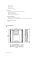
Chapter II Electric Wiring ) Illustration and definition for terminals 4.1 Definition of JA port (0~16-path input) http://www.adtechcn.
Line No.
4.2 Definition of JB port (17~33-path input) . Line No. Name 1 INCOM2 2 IN17 3 IN18 4 IN19 5 IN20 6 IN21 7 IN22 8 IN23 9 IN24 10 IN25 11 IN26 12 IN27 13 IN28 14 IN29 15 IN30 16 IN31 17 IN32 18 IN33 http://www.adtechcn.
4.3 Definition of JC port (18-path input) . Line No. Name Definition 1 24VGND Shared output 2 OUT0 Regular 0 ~ 17 3 OUT1 4 OUT2 5 OUT3 6 OUT4 7 OUT5 8 OUT6 http://www.adtechcn.
9 OUT7 10 OUT8 11 OUT9 12 OUT10 13 OUT11 14 OUT12 15 OUT13 16 OUT14 17 OUT15 18 OUT16 19 OUT17 20 +24V +24V power input for loading (requiring external 12~+24 V power) 4.4 Definition of axis X’s port (axis X’s pulse and direction) JCP1 PUCOM 1 EXT_VCCA 9 2 10 +24V 3 24VGND 11 4 XECA+ XECAXECB+ XECB- 12 5 13 6 14 7 15 8 XPU+ XPUXDR+ XDRXALARM OUT18 XECZ+ XECZ- DB15 15-pin female jack (same as lathe and milling machine) http://www.adtechcn.
Line No.
JCP2 PUCOM 1 EXT_VCCA Y PU+ 9 2 Y PU- 10 +24V 3 24VGND Y DR+ 11 4 Y ECA+ Y ECAY ECB+ Y ECB- Y DR- 12 5 Y ALARM 13 6 OUT19 14 7 Y ECZ+ 15 8 Y ECZ- DB15 15-pin female jack (same as lathe and milling machine) Line No.
13 YECA-(IN44) Phase A’s input - for axis Y’s encoder 14 YECB+(IN45) Phase B’s input + for axis Y’s encoder 15 YECB-(IN45) Phase B’s input - for axis Y’s encoder 4.6 Definition of axis Z’s port (axis Z’s pulse and direction) JCP3 PUCOM EXT_VCCB +24V 1 9 2 10 3 11 4 ZECA+ ZECAZECB+ ZECB- 12 5 13 6 14 7 15 8 ZPU+ ZPUZDR+ ZDRZALARM OUT20 ZECZ+ ZECZ- DB15 15-pin female jack (same as lathe and milling machine) . Line No.
7 ZECZ+(IN40) Phase Z’s input + for axis Z’s encoder 8 ZECZ-(IN40) Phase Z’s input - for axis Z’s encoder 9 EZT_VCCA Driver used for single-end input 10 +24V 24V power + (output to server) 11 24VGND 24V power - (output to server) 12 ZECA+(IN46) Phase A’s input + for axis Z’s encoder 13 ZECA-(IN46) Phase A’s input - for axis Z’s encoder 14 ZECB+(IN47) Phase B’s input + for axis Z’s encoder 15 ZECB-(IN47) Phase B’s input - for axis Z’s encoder 4.
2 APU- Axis A’s pulse signal - 3 ADR+ Axis As direction signal + 4 ADR- Axis A’s direction signal - 5 AALARM (IN37) 6 OUT21 7 AECZ+(IN41) Phase Z’s input + for axis A’s encoder 8 AECZ-(IN41) Phase Z’s input - for axis A’s encoder 9 EAT_VCCA Driver used for single-end input 10 +24V 24V power + (output to server) 11 24VGND 24V power - (output to server) 12 AECA+(IN48) Phase A’s input + for axis A’s encoder 13 AECA-(IN48) Phase A’s input - for axis A’s encoder 14 AECB+(IN49)
4.9 SI 1 (serial interface 1) JCP6 1 6 TX1 2 RX1 3 7 8 VDD50 4 9 5 母头 Female jack DB9 Line No. Name Definition 1 NC Not connected 2 TX1 Transmit data 3 RX1 Receive data 4 GND Power’s grounding 5 GND Power’s grounding 6 NC 7 VDD5.0 Provide 5V power to external devices 8 VDD5.
) Standard USB interface (USB) ) Standard Ethernet interface (RJ45) When the host is directly connected to the Control Card, crossover cables will be used for the connection. In other words, one end of the wires adopts standard 568B line order, and the other 568A line order. ) Connection for input signal Optical coupler input The INCOM terminal should be connected to the positive pole of the external power source and the input signal to the corresponding pin.
) Connection for pulse output signal 1. Differential mode: This mode is suitable for the stepping driver and most of the server drivers with independent pulse and direction input. It is recommended this mode is used, for it provides high anti-interference capacity. Driver of stepping motor Driver of server motor 2. Single-end mode This mode was used for the stepping motors, with which the anodes of pulse and direction were connected together in early time.
) Connection for output signal The switch value of this control system is output through the open collector, with JC1 as both the shared terminal and GND of the loaded power source. In actual use, the operator should connect the Pin 20 of JCI to +24V, and the output point is enabled at low level. The load should be connected to somewhere between +24V and the output point.
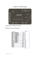
Chapter III System Functions ) Preset drive “Preset drive” means pulses of a set number are output with a fixed velocity or acceleration/deceleration. This function is performed when the tool needs to move to a specific position or execute a specific action. The mechanism of preset drive for acceleration/deceleration is shown in the figure below.
) Continuous drive In continuous drive mode, the output of drive pulses will keep going till the stop commands of high position or external stop signal is enabled. This function can be performed when home position search, scanning or control of motor speed is needed. ) Velocity curve The drive pulses of each axis are output through the preset drive commands with positive/negative direction or through the continuous drive commands.
Linear acceleration/deceleration drive “Linear acceleration/deceleration drive” means the system accelerate to the set drive velocity from start velocity in a linear fashion. In Set-speed mode, the acceleration counter counts the number of pulses accumulated during the acceleration process. When the number of remaining pulses is smaller than that of accumulated pulses, the system will begin to decelerate (automatically). In deceleration, the velocity will be lowered to the start value in a linear fashion.
Velocity Acceleration stops Number of output pulses Number of pulses consumed during acceleration Time Triangle prevention for linear acceleration and deceleration ) Speed mode The speed mode of ADT-8840 falls into two categories, namely, self-define mode and set-speed mode. The former is the default value in the system, while the latter can be set through the function “adt8840a_set_speed_mode()” at the upper PC.
downloads the commands from the buffer by batches, it must know the remaining space in the buffer through the query command “adt8840a_get_buff_depth()”, so as to avoid the overflow of software cache. In this mode, only when the current command is fully executed, can the next command be executed.
Two-phase pulse input mode Count upward Count downward Up/down pulse input mode ) Interpolation The controller can perform the linear interpolation for any 2-4 axes. During the interpolation process, the interpolation computation is carried out under the pulse’s basic time order of the designated axis X. Therefore, such parameters as the designated axis X’s start velocity and drive velocity should be set before the interpolation command is executed.
Hardware buffer interpolation As for the control card without the hardware interpolation function, if the next interpolation is needed after the previous one is ended, it can only inquire whether the previous interpolation is finished so that the next data of the next interpolation can be output.
) Hardware limit signal The hardware limit signal (LMT+ ,LMT-) serves as the input signal that limits the drive pulse of both positive and negative direction drives. When the limit signal and its logic level are both enabled, the motion of the concerning axis will stop immediately. ) Signal corresponding to server motor Input signals connected to the driver of the servo motor include INPOS (in-position signal) and ALARM (alarm signal).
Uart_show Switch for showing the debugging state of serial interface 36 adt8840a_set_stop0_mode Stop mode (software buffer) 36 adt8840a_set_stop1_mode Stop mode (software buffer) 37 adt8840a_set_limit_mode Limit mode 37 adt8840a_set_pulse_mode Pulse mode 37 adt8840a_get_status Get single-axis drive status 38 adt8840a_get_inp_status Get interpolation drive status 39 adt8840a_get_int_status Get interruption status 39 adt8840a_set_acc Set acceleration (software buffer) 39 Motion adt
adt8840a_Disable_ADT834INT 50 adt8840a_read_fifo Get buffer status 50 1-axis hardware buffer interpolation (software buffer) 2-axis hardware buffer interpolation adt8840a_fifo_inp_move2 (software buffer) interpolation 3-axis hardware buffer interpolation adt8840a_fifo_inp_move3 (software buffer) 4-axis hardware buffer interpolation adt8840a_fifo_inp_move4 (software buffer) 51 52 52 52 adt8840a_FS_Remove Delete file 53 adt8840a_Net_Setup Network configuration for control card 53 adt8840a
G02(G2) G03 (G3) To indicate the circle center: Take X and Y as the coordinates of the endpoint of the arc, and I and J as the coordinates of the start point of the arc relative to the circle center. To indicate the radius: Take X and Y as the coordinates of the endpoint of the arc, and R as the radius.
M10 Tighten tool M10(OUT5) Tighten tool M11 Loosen tool M11 Loosen tool M20 Tools bank advances M20(OUT6) Tools bank advances M21 Tools retreat M21 Tools bank retreat M32 Turn on lubrication M32(OUT4) Turn on lubrication M33 Turn off lubrication M33 Turn off lubrication M0 Program end M0(OUT0) Output 500ms pulse M1 Program end M1 Output high level M2 End OFF M2 Output low level M6 Output 7 ON M6(OUT7) Universal output M7 Output 7 OFF M7 Universal output M12 Outpu
OFF M34 Output ON 16 M35 Output OFF 16 M36 Output ON 17 M37 Output OFF 17 M34(OUT16) Universal output M35 Universal output M36(OUT17) Universal output M37 Universal output Note: For standard output, the user can refer to the standards for milling machine. The user can define them as universal output in accordance with the actual situation. Special commands L http://www.adtechcn.com Logic judgment command (for example, L16 is used for examining the signal of point IN16.
Chapter V Definitions of ADT8840's Library Functions ) 1. Basic parameters setup 1.1 DeviceAddr_init( ) Name void DeviceAddr_init(void) Definition Initialization of device interface’s address Input parameter None Output parameter None Return value None Note Initialization should be first performed before the motion function is used 1.
1.5 Get_sock ( ) Name unsigned int Get_sock(int dev_num) Definition Get the raw socket for network communication based on the device number Input parameter dev_num:device number Output None parameter Return value 1.
Return value 0: execution OK; -1: transmission abnormity; -4: disabled device interface Note Signal in disabled state in initialization, stop at low level; 1.
) 2. Drive status detection 2.1 adt8840a_get_status( ) Name int adt8840a_get_status(int dev_num ,int axis, int *value) Definition Get axis’s drive status Input parameter Output parameter Return value Note 2.
Output parameter Return value Note Value: pointer of interruption status; 0: interruption end; non-0: interruption under way 0: execution OK; 1: execution failure; -1: transmission abnormity; -2: response overtime; -3: abnormal data received; -4: disabled device interface None ) 3. Motion parameters setup 3.
Return value 0: execution OK; -1: transmission abnormity; -4: disabled device interface Note None 3.
Output parameter None Return value 0: execution OK; -1: transmission abnormity; -4: disabled device interface Note Logic-position counter can be written and read at any time. 3.
) 4.
The unit of the parameter is the same as set value of drive velocity—V. Note 4.4 With this function, the drive velocity can be obtained at any time. adt8840a_all_command_pos( ) Name int adt8840a_all_command_pos( int dev_num,long pos[]) Definition Get the logic positions of four axes Input parameter int dev_num: device number Output long pos[]: receive the data of logic position for each axis; parameter pos[1]: position of axis 2; pos[2]: position of axis 3; pos[3]: position of axis.
) 5. Drive 5.1 adt8840a_pmove( ) Name int adt8840a_pmove(int dev_num,int axis, long pulse) Definition Preset drive dev_num: device number axis: axis number (1 - 4) Input parameter pulse: Output pulses >0 Positive direction movement <0 Negative direction movement Scope (-268435455~+268435455) Output None parameter Return value The parameters needed by the velocity curve must be set before the drive command is Note 5.
dev_num: device number axis: axis number (1 - 4) Input parameter pulse: Output pulses >0 Positive direction movement <0 Negative direction movement Scope (-268435455~+268435455) Output parameter Return value 0: execution OK; -1: transmission abnormity; -4: disabled device interface The parameters needed by the velocity curve must be set before the drive command is Note 5.4 None written.
5.6 adt8840a_sudden_stop( ) Name int adt8840a_sudden_stop(int dev_num,int axis) Definition Sudden stop Input parameter Output dev_num: device number axis: axis number (1 - 4) None parameter Return value It immediately stops the pulse output when the drive is under way, even if the Note 5.
Definition Input parameter Output Four-axis linear interpolation dev_num: device number pulse1,pulse2,pulse3, pulse4: relative distance the axis travels None parameter Return value 0: execution OK; -1: transmission abnormity; -4: disabled device interface Note i. The interpolation speed is based on the axis X’s speed. ii. At present, the four-axis interpolation is performed through the fixed axis 1, 5.10 axis 2, axis 3 and axis 4.
Note 5.12 The coordinates of any three points in the plane can’t be on the same point or line. adt8840a_arc( ) Name int adt8840a_arc(int dev_num,int axis1,int axis2,float cen[]) Definition Arc machining parameter int dev_num: device number int axis1: plane axis 1 Input parameter int axis2: plane axis 2 float cen[]: arc’s parameter structure.
) 6. Input and output of switch value 6.
6.4 adt8840a_read_8bit( ) Name int adt8840a_read_8bit(int dev_num,int ios,int *value) Definition Keep reading the status of 8 input points Input parameter Output int dev_num: device number int ios: initial IO number int value: the statuses of successive 8 input points, which correspond to 0-7 respectively. parameter Return value Note 0: execution OK; 1: execution failure; -1: transmission abnormity; -2: response overtime; -3: abnormal data received; -4: disabled device interface None ) 7.
) 8. Hardware buffer 8.1 adt8840a_reset_fifo( ) Name int adt8840a_reset_fifo(int dev_num) Definition Reset buffer. In other words, clear all commands in the buffer. Input parameter dev_num: device number Output None parameter Return value Clearing FIFO (first-in-first-out) is only to clear the data in the buffer, and it won’t stop the Note 8.2 0: execution OK; -1: transmission abnormity; -4: disabled device interface current motion.
Name int adt8840a_fifo_inp_move1(int dev_num ,int axis1, long pulse1, long speed) Definition Buffer single drive dev_num: device number Input parameter axis1: axis number (1-4) pulsel: relative distance that the axis travels speed: moving speed Output None parameter Return value 0: execution OK; -1: transmission abnormity; -4: disabled device interface Note None 8.
Return value 0: execution OK; -1: transmission abnormity; -4: disabled device interface Note None 8.
) 9. System 9.1 adt8840a_FS_Remove( ) Name int adt8840a_FS_Remove(int dev_num,const char *pFileName) Definition Delete file Input parameter Output int dev_num: device number char *pFileName: file’s path name None parameter Return value Note 9.
Note 9.4 None adt8840a_set_buff_mode( ) Name int adt8840a_set_buff_mode(int dev_num,int buffmode) Definition Set the software buffer mode Input parameter Output int dev_num: device number int mode: 0: software buffer enabled; 1: software buffer disabled None parameter Return value 0: execution OK; -1: transmission abnormity; -4: disabled device interface Note None 9.
int dev_num: device number int mode: upload mode 0: upload the currently used parameters of control card to host Input parameter 1: upload parameters from system files of control card to host char *file: file name of system parameters. If null character string is input, it means the default fine name “system.ini” is used. Output None parameter Return value 0: execution OK; -1: transmission abnormity; -4: disabled device interface Note None 9.
9.10 adt8840a_stop_all( ) Name int adt8840a_stop_all(int dev_num) Definition Function for returning to home position Input parameter int dev_num: device number Output None parameter Return value 0: execution OK; -1: transmission abnormity; -4: disabled device interface Note None http://www.adtechcn.
) 10. G code 10.1 adt8840a_download_gfile ( ) Name int adt8840a_upload_gfile(int dev_num) Definition Download G-code program (.dot) from local PC to control card Input parameter int dev_num: device number Output None parameter Return value 0: execution OK; -1: transmission abnormity; -4: disabled device interface Note None 10.
Definition Run G-code files in control card for machining Input parameter int dev_num: device number Output None parameter Return value 0: execution OK; -1: transmission abnormity; -4: disabled device interface Note None 10.
Chapter VI Use of Library Functions for Motion Control ) 1. Overview of ADT-8840’s Function Library The function Library of ADT-8840 serves as interfaces with which the user can operate the control card to realize the corresponding functions. ) 2.
) 3. Help for debugging in developing through application The function library of ADT-8840 provides help on debugging. (1) Use the debugging tool to display the input parameters actually received by the control card and the execution results. The displaying state of serial interface debugging is enabled or disabled through the function “Uart_show()”, with default as “disabled”.
Note: The library functions, namely, “DeviceAddr_init() and TCP_Conn()”, serve as the “gate” through which ADT-8840 passes. Only after the motion control card is successful initialized by using these two functions, can other functions be used effectively. ) Speed setting 2.1 Uniform motion It is easy to carry out the setting. What the user needs to do is to set the drive velocity with the same value as the start velocity. No need to set other parameters.
) Signal STOP0 and STOP1 STOP0 and STOP1 are signals each axis has. Thus there are eight STOP signals totally, which are mainly used when the machine needs to return to the home position. To return to the home position, one or multiple signals can be used in accordance with the situation. However, it should be noted that, as this signal is defined as deceleration stop, a deceleration switch can be added in front of the home position switch when the system returns to the home position at high speed.
Chapter VIII Examples of Programming for Developing Motion Control Card All motion-control functions are of immediate return. When the drive commands is sent out, the motion process will be controlled by the control card. At the time, the user can oversee the whole motion process through the upper PC in a real-time manner, or compulsorily stop the motion. Note: When an axis is moving, it is not allowed to send new drive command to it.
'we have 'packaged all library functions by referring to the type on the basis of the ' function library of the control card. The following example only involves 'one motion control card. '******************************************************** Public Result As Integer 'return value Const MAXAXIS = 4 'max. axis number '***********************initialize functions**************************** 'This function includes the library function commonly used in the initialization of the control card.
'****************************************************************************** *** Public Function Setup_Speed(ByVal axis As Integer, ByVal startv As Long, ByVal speed As Long, ByVal add As Long) As Integer If (startv - speed >= 0) Then Result = adt8840a_set_startv(devnum, 0, axis, startv) adt8840a_set_speed devnum, 0, axis, startv Else Result = adt8840a_set_startv(devnum, 0, axis, startv) adt8840a_set_speed devnum, 0, axis, speed adt8840a_set_acc devnum, 0, axis, add End If End Function '*****************
'Parameters: axis1 , axis2 – axis number engaged in the interpolation pulse1, pulse2-number of output pulses of the corresponding axis 'Return value=0: correct; return value=1: error '******************************************************* Public Function Interp_Move2(ByVal axis1 As Integer, ByVal axis2 As Integer, ByVal pulse1 As Long, ByVal pulse2 As Long) As Integer Result = adt8840a_inp_move2(devnum, 0, axis1, axis2, pulse1, pulse2) Interp_Move2 = Result End Function '******************* function for in
Public Function StopRun(ByVal axis As Integer, ByVal mode As Integer) As Integer If mode = 0 Then Result = adt8840a_sudden_stop(devnum, axis) Else Result = adt8840a_dec_stop(devnum, axis) End If End Function '*******************function for position setting******************** 'This function is used to set the logic position and actual position ' Parameters: axis-axis number; pos-position value ' Mode 0: set logic position; 1: set actual position 'Return value=0: correct; return value=1: error '************
'*******************function for getting to know the motion status******************** 'This function is used to get to know the drive status and interpolation status of each axis ' Parameters: axis-axis number; value-status (0-drive end; non-0: drive under way) ' Mode 0-get to know the drive status of single axis; non-0: get to know the drive status of interpolation 'Return value=0: correct; return value=1: error '******************************************************* Public Function Get_MoveStatus(ByVa
'This function is used to set the work mode of pulse 'Parameters: axis-axis number; value-pulse’s work mode: 0: pulse+pulse mode; 1: pulse+direction mode 'Return value=0: correct; return value=1: error 'Default pulse’s work mode: pulse+direction mode 'This program employs the positive logic pulse and positive logic for direction output signals, which are the default values '****************************************************************************** Public Function Setup_PulseMode(ByVal axis As Integer, B
'********************set mode of stop1 signal ********************* 'This function is used to set the mode of stop1 signal 'Parameters: axis-axis number ' Value: 0—disabled; 1—enabled ' Logic: 0—low level enabled; 1—high level enabled 'Default values: disabled 'Return value=0: correct; return value=1: error '************************************************************* Public Function Setup_Stop1Mode(ByVal axis As Integer, ByVal value As Integer, ByVal logic As Integer) As Integer Setup_Stop1Mode = adt8
1.3.2 The initialization codes are in the uploaded events, which are described as follows: Private Sub Form_Load() DeviceAddr_init ' initialize the device’s interface address m_MacAddr.Text = "00-AB-CD-00-01-23" 'designate network adapter’s address m_IPAddr.Text = "192.168.0.123" ' designate IP address of control card m_INFO.
accessed by clicking, and send out corresponding drive commands based on the selected objective. The names of the four check boxes (selected objective) are X, Y, Z and A and the codes are described as follows: '***************** judgment of speed setup ************************ ' Setting scope of start velocity and drive velocity: (1~2M) ' Setting scope of acceleration: (1×125~64000×125) '***************************************************** If m_bX.value = vbUnchecked And m_bY.value = vbUnchecked And m_bZ.
'*****************judgment of speed setup **************** ' Setting scope of start velocity and drive velocity: (1~2M) ' Setting scope of acceleration: (1×125~64000×125) '***************************************************** '***************************interpolation*************************************** ' ADT-8840 control card can realize interpolation of any two,, three or four axes '***************************** four-axis interpolation***************************** If m_bX.value = vbChecked And m_bY.
Setup_Speed 1, m_nStartV(0).Text, m_nSpeed(0).Text, m_nAdd(0).Text Interp_Move2 1, 4, m_nPulse(0).Text, m_nPulse(3).Text '********************** interpolation of axis Y and Z****************************** ElseIf m_bY.value = vbChecked And m_bZ.value = vbChecked Then Setup_Speed 2, m_nStartV(1).Text, m_nSpeed(1).Text, m_nAdd(1).Text Interp_Move2 2, 3, m_nPulse(1).Text, m_nPulse(2).Text '********************** interpolation of axis Y and A******************************** ElseIf m_bY.
m_bPLimit(i - 1).value = 1 Else m_bPLimit(i - 1).value = 0 End If ' detect positive limit (XLMT+ : 5,YLMT+ :7,ZLMT+ :9,WLMT+ :11) Read_Input (i - 1) * 2 + 5, value If value = 0 Then m_bNLimit(i - 1).value = 1 Else m_bNLimit(i - 1).value = 0 End If 'detect stop 0 (XSTOP0 : 0,YSTOP0 :1,ZSTOP0 :2,WSTOP0 :3) Read_Input (i - 1), value If value = 0 Then m_bStop0(i - 1).value = 1 Else m_bStop0(i - 1).
1.5 Stop module The stop module is mainly used to control sudden events during the drive process that require immediate stop of all axes’ motions. The codes of stop module are provided at the button “CmdStop” where they can be accessed by clicking. The codes are described as follows: Private Sub Stop_Click() For i = 1 To 4 StopRun i, 0 Next i End Sub ) 2. VC programming 2.1 Preparation (1) Create a new project, and save it as “VCExample.
int Setup_Pos(int axis, long pos, int mode); int Write_Output(int number, int value); int Read_Input(int number, int &value); int Get_CurrentInf(int axis, long &LogPos, long &ActPos, long &Speed); int Get_Status(int axis, int &value, int mode); int StopRun(int axis, int mode); int Interp_Move4(long value1, long value2, long value3, long value4); int Interp_Move3(int axis1, int axis2, int axis3, long value1, long value2, long value3); int Interp_Move2(int axis1, int axis2, long value1, long value2); int Axis
{ for (int i = 1; i<=MAXAXIS; i++) { Result=adt8840a_set_command_pos(devnum, mode,i,0); adt8840a_set_actual_pos(devnum, mode,i,0); adt8840a_set_startv(devnum, mode,i,0); adt8840a_set_speed(devnum, mode,i,0); adt8840a_set_acc(devnum, mode,i,0); } if(Result==0 ) return 1; else return Result; } else return -1; } /****************************set speed module***************************** Judge from the parameter whether it is uniform speed or acceleration/deceleration Set the start velocity, drive velocity and a
/*********************single-axis function********************** This function is used for driving the single axis Parameters: axis- axis number; pulse- number of output pulse Return value=0: correct; return value=1: error **********************************************************/ int CCtrlCard::Axis_Pmove(int axis, long value) { Result = adt8840a_pmove(devnum,0, axis, value); return Result; } /*******************function for interpolation of any two axes******************** This function is used to drive
********************************************************************/ int CCtrlCard::Interp_Move4(long value1, long value2, long value3, long value4) { Result = adt8840a_inp_move4(devnum,0, value1, value2, value3, value4); return Result; } /********************************* stop running********************************** This function is used to stop running, including immediate stop and stop by deceleration Parameters: axis-axis number; mode: deceleration method (0-immediate stop; 1-stop by deceleration) Re
/********************* get current information on motion ************************ This function is used to get the current information on logic position, actual position and running speed Parameters: axis-axis number; LogPos-logic position; ActPos-actual position; Speed-running speed Return value=0: correct; return value=1: error ************************************************************************/ int CCtrlCard::Get_CurrentInf(int axis, long &LogPos, long &ActPos, long &Speed ) { Result = adt8840a_get_
**************************************************************/ int CCtrlCard::Setup_Pos(int axis, long pos, int mode) { if(mode==0) { Result = adt8840a_set_command_pos(devnum,0,axis, pos); } else { Result = adt8840a_set_actual_pos(devnum,0, axis, pos); } return Result; } /********************set pulse output mode ********************** This function is used to set the work mode of pulse Parameters: axis-axis number; value-pulse’s work mode: 0: pulse+pulse mode; 1: pulse+direction mode Return value=0: corre
/********************set mode of stop0 signal ********************* This function is used to set the mode of stop0 signal Parameters: axis-axis number Value: 0—disabled; 1—enabled Logic: 0—low level enabled; 1—high level enabled Default values: disabled Return value=0: correct; return value=1: error *********************************************************/ int CCtrlCard::Setup_Stop0Mode(int axis, int value, int logic) { Result = adt8840a_set_stop0_mode(devnum,0, axis, value ,logic); return Result; } /*****
2.3 Implementation module 2.3.1 Interface configuration Note: (1) Speed setting—to set start velocity, drive velocity and acceleration of each axis; position setting—to set the drive pulse of each axis; drive information—to display the logic position, actual position and running speed of each axis in a real-time manner. (2) Drive objective—to select the drive objective to determine the axis that’s engaged in the interaction or interpolation.
m_nStartvY = 100; m_nStartvZ = 100; m_nStartvA = 100; //********* set the default drive velocity as 2000******** m_nSpeedX = 2000; m_nSpeedY = 2000; m_nSpeedZ = 2000; m_nSpeedA = 2000; //********* set the default acceleration as 2500********** m_nAddX = 2500; m_nAddY = 2500; m_nAddZ = 2500; m_nAddA = 2500; //******** set the default target position as 1000000****** m_nPulseX = 1000000; m_nPulseY = 1000000; m_nPulseZ = 1000000; m_nPulseA = 1000000; UpdateData(FALSE); SetTimer(MAINTIMER,100,NULL); // start th
g_CtrlCard.Setup_Speed(2, m_nStartvY, m_nSpeedY, m_nAddY); } if(m_bZ ) { //************* set speed of axis Z **************// g_CtrlCard.Setup_Speed(3, m_nStartvZ, m_nSpeedZ, m_nAddZ); } if(m_bA ) { //************* set speed of axis A**************// g_CtrlCard.Setup_Speed(4, m_nStartvA, m_nSpeedA, m_nAddA); } // drive command //************* drive of axis X ***************// if(m_bX) g_CtrlCard.Axis_Pmove(1, m_nPulseX); //************* drive of axis Y ***************// if(m_bY) g_CtrlCard.
//************ two-axis interpolation***********// if(m_bX && m_bY && !m_bZ && !m_bA) // interpolation of axis X and Y { g_CtrlCard.Setup_Speed(1, Startv[0], Speed[0], Add[0]); g_CtrlCard.Interp_Move2(1, 2, Pulse[0], Pulse[1]); } else if(m_bX && !m_bY && m_bZ && !m_bA) // interpolation of axis X and Z { g_CtrlCard.Setup_Speed(1, Startv[0], Speed[0], Add[0]); g_CtrlCard.Interp_Move2(1, 3, Pulse[0], Pulse[2]); } else if(m_bX && !m_bY && !m_bZ && m_bA) // interpolation of axis X and W { g_CtrlCard.
else if(m_bX && m_bY && m_bZ && !m_bA) // interpolation of axis X, Y and Z { g_CtrlCard.Setup_Speed(1, Startv[0], Speed[0], Add[0]); g_CtrlCard.Interp_Move3(1, 2, 3, Pulse[0], Pulse[1], Pulse[2]); } else if(m_bX && m_bY && !m_bZ && m_bA) // interpolation of axis X, Y and W { g_CtrlCard.Setup_Speed(1, Startv[0], Speed[0], Add[0]); g_CtrlCard.Interp_Move3(1, 2, 4, Pulse[0], Pulse[1], Pulse[3]); } else if(m_bX && !m_bY && m_bZ && m_bA) // interpolation of axis X, Z and W { g_CtrlCard.
// read positive/negative limit and stop0 // //*********************************************************// void CVCExampleDlg::OnTimer(UINT nIDEvent) { long log=0,act=0,spd=0; UINT nID1[]={IDC_POS_LOGX,IDC_POS_LOGY,IDC_POS_LOGZ,IDC_POS_LOGW}; UINT nID2[]={IDC_POS_ACTX,IDC_POS_ACTY,IDC_POS_ACTZ,IDC_POS_ACTW}; UINT nID3[]={IDC_RUNSPEED_X,IDC_RUNSPEED_Y,IDC_RUNSPEED_Z,IDC_RUNSPEED_W} ; CStatic *lbl; CString str; int status[4]; for (int i=1; i
//******************************************* UINT nIDIN1[]={ IDC_STOP0_X,IDC_STOP0_Y, //X,Y home position IDC_STOP0_Z,IDC_STOP0_W, //Z,A home position IDC_LIMIT_X,IDC_LIMIT_X2, //Positive/negative limit of axis Y IDC_LIMIT_Y,IDC_LIMIT_Y2, // Positive/negative limit of axis Y IDC_LIMIT_Z,IDC_LIMIT_Z2, // Positive/negative limit of axis Z IDC_LIMIT_W,IDC_LIMIT_W2 }; // Positive/negative limit of axis A CButton *btn; int value=0; for (i=0; i<12; i++) { g_CtrlCard.
btn->EnableWindow(TRUE); btn=(CButton*)GetDlgItem(IDC_BUTTON_CMOVE); btn->EnableWindow(TRUE); btn=(CButton*)GetDlgItem(IDC_BUTTON_INPMOVE); btn->EnableWindow(TRUE); btn=(CButton*)GetDlgItem(IDC_BUTTON_CLEARPOS); btn->EnableWindow(TRUE); btn=(CButton*)GetDlgItem(IDC_BUTTON_BASEPARA); btn->EnableWindow(TRUE); } else { //********** drive under way********** btn=(CButton*)GetDlgItem(IDC_BUTTON_PMOVE); btn->EnableWindow(FALSE); btn=(CButton*)GetDlgItem(IDC_BUTTON_CMOVE); btn->EnableWindow(FALSE); btn=(CButton*)G
Chapter IX Network Configuration and Serial-Interface Debugging ) 1. Overview ADT-884 is designed on the basis of the control and transmission protocol for Ethernet and TCP/IP protocol. With bandwidth of 10Mbps, ADT-884 can be operated in the LAN whose bandwidth is 100Mbps. At present, ADT-884 and its supporting software can be used in an Ethernet-based LAN or connected to PC’s network interface with the crossover cables.
with ADT-8840) before connection to other systems, so as to ensure the exclusiveness of IP address and network adapter’s address in the LAN. 3.1 Serial-interface debugging First connect ADT-8840 to serial interface of PC through the communication cable and then run the serial-interface debugging tool “SSCOM32.EXE” (see the tool attachment).
the user didn’t re-configure them. Defaults of network configurations are as follows: IP address: 192.168.0.123 Subnet masl: 255.255.255.0 Default gateway: 192.168.0.1 Address of network adapter (MAC): 00-AB-CD-00-01-23 3.2 Network configuration of ADT-8840 The user can activate the window of serial-interface software and press any key to enter the interface of configuration within 30 seconds after ADT-8840 is started, as shown in Figure 2. Two commands for configuration mode appear in Figure 2.
Figure 2 After the user enters the command “:000004”in the test/configuration interface and click Send or Enter, the system will enter the state of network configuration for the control card.
Figure 4 Figure 5 After the network configuration is completed successfully and saved, prompt will appear in the http://www.adtechcn.
interface saying the control card must be re-started to make the configuration effective. After the control card is restarted, in the power-on information the user will find “find network configuration files, configuration is under way…”, as shown in Figure 6. Figure 6 The network configuration of ADT-8840 can also be realized through the function “adt8840a_Net_Setup()”in the application after the network is successfully connected. ) 4.
window for TCP/IP protocol, as shown in Figure 7, 8, 9 and 10. Figure 7 Figure 8 http://www.adtechcn.
Figure 9 http://www.adtechcn.
Figure 10 http://www.adtechcn.
Figure 11 In the properties window for TCP/IP protocol, select “use the IP address below”. Then the user can set the host’s IP address, subnet mask and default gateway in accordance with the subnet number of the LAN where the host is installed. If no real gateway exists in the subnet, the gateway can be set as the number of the first host in the subnet, like “192 . 168 . 0 . 1”. In actual use, the subnet number should be consistent with that of the host.
) 5. Network connection and troubleshooting 5.1 Initialization of application In the start-up process of the host’s application, the function “DeviceAddr_init()”must be used to initialize the interfaces of the devices, which number 63 maximally. When initialization is completed, the function “Close_all()”should be used to close the application and release all connections and resources. 5.
■ Connection with start-shape topology The controlling host and the device are connected to each other via the switch or hub with standard 568A straight-through cable. In actual practice, we recommend you take the related specification of industrial Ethernet as the criterion. Device 2 Device 3 Device 4 Device 5 Device 6 Device 1 Switch or hub Switch or hub Controlling host Other hosts 5.
Figure 13 5.5 Troubleshooting for network connection 1) Inconsistent IP address and network adapter address of device as they are not re-configured. Set the network items for the device again 2) IP address of the device is not in the same subnet as that of the host. Set them in the same subnet, or change the subnet mask. 3) Multiple devices with the same IP addresses and network adapter addresses exist in the LAN. Set the network items for the device again. 4) Network cables are not matched to each other.
connected to each other through crossover cable, while the device and the HUB or router can be connected to each other through either crossover cable or straight-through cable. 5) IP address and MAC address of the device don’t exist at the time of network connection. Use the serial-interface software tool to get (or modify) the real IP address and MAC address of the control card, and confirm their exclusiveness in the subnet. 6) Unreliable physical connection, check 7) Error of default gateway setting.
) 7. Debugging and observing program running through serial interface ADT-8840 provides methods to help developers debug program through observation of the information on running. After serial interface 0 is connected to PC, run the serial-interface debugging software “SSCOM32.EXE”. Then the user can open or close the corresponding debugging information through the function “Uart_show(int dev_num,unsigned int on_off)” in the application.
Check whether the wiring is correct before the system is electrified. Pay attention to the mutual influence between the high and low voltage (if you feel confused, refer to the wiring diagram of the joint box) 1. Check whether the driver’s current is excessively high or low and subdivision setup is correct. 2. Check whether the motor and the corresponding axis are correctly set. 3. Check whether the input and output circuits match each other. 4.