
User`s manual

http://www.adtechcn.com 18
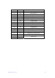
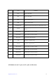
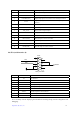
2 APU- Axis A’s pulse signal -
3 ADR+ Axis As direction signal +
4 ADR- Axis A’s direction signal -
5 AALARM (IN37) Regular input signal, can be used as server alarm input of axis A
6 OUT21
Regular input signal, can be used as server full capacity and other
functions
7 AECZ+(IN41) Phase Z’s input + for axis A’s encoder
8 AECZ-(IN41) Phase Z’s input - for axis A’s encoder
9 EAT_VCCA Driver used for single-end input
10 +24V 24V power + (output to server)
11 24VGND 24V power - (output to server)
12 AECA+(IN48) Phase A’s input + for axis A’s encoder
13 AECA-(IN48) Phase A’s input - for axis A’s encoder
14 AECB+(IN49) Phase B’s input + for axis A’s encoder
15 AECB-(IN49) Phase B’s input - for axis A’s encoder
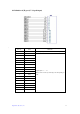
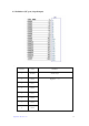
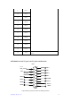
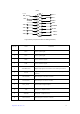
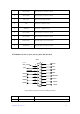
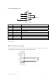
4.8 SI 0 (serial interface 0)
公头
JCP5
5
9
4
8
3
7
2
6
1
RX0
TX0
VDD50
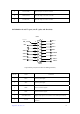
Male jack DB9
Line No. Name Definition
1 NC Not connected
2 TX0 Transmit data
3 RX0 Receive data
4 GND Power’s grounding
5 GND Power’s grounding
6 NC Not connected
7 VDD5.0 Provide 5V power to external devices
8 VDD5.0 Provide 5V power to external devices
9 NC Not connected
SI 0 is normally used for displaying the information of running during network configuration and
debugging.