
User`s manual


http://www.adtechcn.com 22
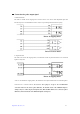
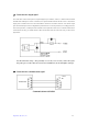
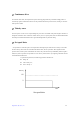
) Connection for output signal
The switch value of this control system is output through the open collector, with JC1 as both the shared terminal
and GND of the loaded power source. In actual use, the operator should connect the Pin 20 of JCI to +24V, and the
output point is enabled at low level. The load should be connected to somewhere between +24V and the output
point. The internal output circuit is safeguarded by mechanisms of over-current protection, over-voltage protection,
short circuit protection, overheat protection and follow-current protection. However, if an external sensible load is
connected, like the relay, you should connect a follow-current diode at the two ends of the relay, as shown in the
figure below:
Note: Recommended voltage: < 24V (preferably not over 30V). Never reversely connect the negative
and positive poles, nor allow the load to have short circuit. Otherwise, the module might be damaged.
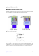
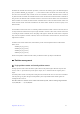
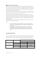
) Connection for communication signal
Communication mode RS232
or
Control Card
PC