
User`s manual


http://www.adtechcn.com 29
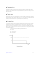
Hardware buffer interpolation
As for the control card without the hardware interpolation function, if the next interpolation is needed after the
previous one is ended, it can only inquire whether the previous interpolation is finished so that the next data of the
next interpolation can be output. If the upper PC runs slowly, or a multipurpose operating system runs in the upper
computer, there will be pause between the two interpolations, which not only affects the effects of interpolation,
but also makes it hard to raise the interpolation speed.
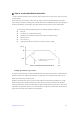
With the hardware buffer interpolation in ADT-8840, this problem can be properly solved, for a great number of
interpolation commands can be continuously saved in the space of hardware buffer. Even if the system is executing
an interpolation command for motion, an interpolation command can be written.
When a command is written into an empty hardware buffer, the control card will immediately execute the first
written command on a first-in-first-out basis. The system will stop once the execution of the current interpolation
command is completed at the time the hardware buffer is empty. The user should judge whether the buffer space is
full when saving the interpolation commands into it. If it is full, no more command can be written. Otherwise, the
commands might be lost.
With hardware buffer interpolation, the pause between two interpolations can be effectively avoided. Even if the
computer runs slowly, good effects can be obtained.
Note:
1. When a hardware buffer interpolation command is being executed, if the interpolation
motion needs to be stopped immediately, the operator must first clear the buffer and then
stop the motion.
2. When a hardware buffer interpolation command is being executed, no other motion
command should be executed simultaneously. Otherwise, motion confusion will arise.
3. Interpolation buffer only works in even speed state, not in acceleration and deceleration
state.
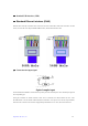
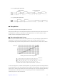
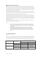
) Pulse output mode
As shown in the table below, two modes are available for the drive output pulses. In independent 2 pulse output
mode, drive pulses are output from PU/CW when it is a positive direction drive, and from DR/CCW when negative.
In 1 pulse output mode, drive pulses are output from PU/CW and direction signals are output from DR/CCW.
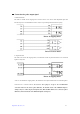
When positive logic setting is available for pulse/direction
Wave shape of output signal
Pulse output mode Drive direction
PU/CW Signal DR/CCW Signal
+direction drive output
Low Level
Independent 2 pulse
output mode
-direction drive output Low Level
+direction drive output
Low Level
1 pulse output mode
-direction drive output
High Level