ATLAS Router User Manual Part Number 1200263L1-1.2A 61200263L1-1.
901 Explorer Boulevard P.O. Box 140000 Huntsville, AL 35814-4000 (256) 963-8000 © 1998 ADTRAN, Inc. All Rights Reserved. Printed in U.S.A.
Table of Contents List of Figures ..................................................................................................................................................... v Chapter 1. Router ........................................................................................................................................... 1-1 Router Overview ..............................................................................................................................................
Table of Contents iv ATLAS Router User Manual 61200263L1-1.
List of Figures Figure 1-1. Figure 1-2. Figure 3-1. Figure 3-2. Figure 3-3. Figure 3-4. Figure 3-5. Figure 3-6. Figure 3-7. Figure 4-1. Figure 4-2. Figure 4-3. Figure 4-4. Figure 4-5. Figure 4-6. Figure 4-7. External Routers ........................................................................................................................... 1-1 Internal Routers ............................................................................................................................
List of Figures vi ATLAS Router User Manual 61200263L1-1.
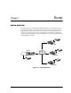
Router Chapter 1 ROUTER OVERVIEW The ATLAS router uses the integral 10BaseT Ethernet port to transmit local area network (LAN) traffic over the wide area network (WAN) to a remote LAN. By integrating the router into the network access device, you benefit from the cost savings of not requiring an external router. Figure 1-1 and Figure 1-2 illustrate a conversion from an application with external routers to one using integral routers within ADTRAN products.
Chapter 1. Router L A N F-T1 TSU 100e with router module ATLAS 800PLUS with router firmware T1 Frame Relay PC L A N F-T1 TSU 100e with router module L A N L A N F-T1 PC PC TSU 100e with router module PC Figure 1-2. Internal Routers The Frame Relay/Router option lets the ATLAS series of Integrated Access Devices act as a voice/data FRAD, a frame relay switch, and an IP router—in addition to the currently available bandwidth management and switch applications.
Chapter 2 Technology Overview IP ROUTING Internet Protocol (IP) routing is performed at layer 3 of the Open System Interconnection (OSI) model. (Refer to the Frame Relay User Manual for a description of the OSI model.) The routing process determines the optimal path for data packets to travel and then moves the data packets along that path. Routers exchange information about paths or routes that reach additional LAN segments.
Chapter 2. Technology Overview 2-2 ATLAS Router User Manual 61200263L1-1.
Operation Chapter 3 OVERVIEW The Router Upgrade provides remote connectivity of LANs within an ATLAS— from LAN-to-WAN connection or from WAN-to-WAN connection. The Router Upgrade is included as part of the frame relay upgrade and includes an IP Router. TERMINAL MENU STRUCTURE The ATLAS uses hierarchical menus to access all of its features. The top-most menu level leads to submenus which are grouped by functionality. All menu items display in the terminal window.
Chapter 3. Operation ROUTER MENU The Router Menu defines, configures, and monitors all ATLAS Router options. Figure 3-2 displays the IP Router menu tree. IP Address Netmask Static Routes Gateway Interface Hops IP Address MAC Address ARP Cache Time Type IP Interface TX Pending IP Address Netmask Routes Gateway Interface Used Flags Hops TTL Network Name Address Subnet Mask Interfaces IARP Mode Far-End Address Protocol MTU Method RIP Updates V2 Secret Figure 3-2.
Chapter 3. Operation IP MENU The IP Menu defines and monitors IP routes (see Figure 3-3). Figure 3-3. IP Routes Menu Static Routes The Static Routes Menu manages static IP routes. You can create, modify, and delete routes using this menu (see Figure 3-4). Figure 3-4. Static Routes Menu IP Address Write Security: 3; Read Security: 5 Defines the IP address of the host or network device being routed to.
Chapter 3. Operation Gateway Write Security: 3; Read Security: 5 Defines the IP address of the router to receive the forwarded IP packet. Interface Write Security: 3; Read Security: 5 Defines the interface to which IP packets with this address will be routed. These are either Ethernet or frame relay DLCIs. Hops Write Security: 3; Read Security: 5 Defines the number of router hops required to get to the network or host. Maximum distance is 15 hops.
Chapter 3. Operation Interface Read Security: 5 Displays the interface upon which this entry was found. Tx Pending Read Security: 5 Displays the number of transmit packets pending a reply. Routes The Routes Menu displays the contents of the ATLAS route table. All static and discovered routes are displayed from this menu (see Figure 3-6). Figure 3-6. Routes Menu IP Address Read Security: 5 Displays the IP address of the network or host destination address.
Chapter 3. Operation Interface Read Security: 5 Displays the interface to which IP packets with this address will be routed. Options Local Sent directly to the ATLAS router EN0 IP ATLAS Ethernet port Endpoint Name (DLCI #) Used Read Security: 5 Displays the number of times the router has referenced this route.
Chapter 3. Operation Interfaces The Interfaces Menu (see Figure 3-7) configures and monitors all interfaces connected to the ATLAS router. These include the Ethernet and frame relay DLCIs connected in the Packet Manager/ Packet Cncts. Figure 3-7. Interfaces Menu Network Name Read Security: 5 Displays the name of the interface connected to the ATLAS router.
Chapter 3. Operation IARP (Inverse ARP) Write Security: 3; Read Security: 5 The Inverse ARP (IARP) field is only present when this is a frame-relay network interface. ATLAS always responds to Inverse ARP requests with its IP address for the requested DLCI. Enable Atlas sends Inverse ARP packets in order to determine the IP address on the other end of the virtual circuit. If the Inverse ARP packet is responded to, a route is placed in the IP route table.
Chapter 3. Operation If RIP V2 is used, a user-defined secret will have to be created. Method Write Security: 3; Read Security: 5 Defines the method used to send RIP route advertisements. The options are listed below: None Split Horizon Poison Reverse All routes in the router table are advertised through this interface with no modification of the routing metric. Only advertises routes not learned through this interface.
Chapter 3. Operation 3-10 ATLAS Router User Manual 61200263L1-1.
Configuration Overview and Examples Chapter 4 This chapter provides several step-by-step examples to help you configure your ATLAS. Figure 4-1 illustrates an ATLAS configured for the Router option. 10.100.20.0 10BaseT Router IP Pkt Endpoint 1 T1 Port Frame Relay Network Figure 4-1. ATLAS Configured for the Router Option The general procedure for configuring the ATLAS depicted in Figure 4-1 is as follows: 1. From Packet Manager/Packet Endpnts/Config, create the frame relay packet endpoint.
Chapter 4. Configuration Overview and Examples Example 1: IP Routing Network—ATLAS as the Central-Site Router Example 1 (see Figure 4-2) depicts a typical IP routing network using an ATLAS as the central-site router. (This ATLAS unit is the ATLAS 800PLUS with a frame relay upgrade.) The central-site ATLAS terminates a full T1 (F-T1) frame relay connection from the XYZ service provider, and the internal router terminates the IP traffic.
Chapter 4. Configuration Overview and Examples Step 2: Create the sublinks or DLCIs for frame relay. See Figure 4-4. Figure 4-4. Panel for Creating Sublinks Step 3: Connect the IP traffic to the internal router. See Figure 4-5. Figure 4-5. Panel for Connecting IP Traffic to Internal Router 61200263L1-1.
Chapter 4. Configuration Overview and Examples Step 4: Connect packet endpoint to the appropriate physical interface. See Figure 4-6. Figure 4-6. Panel for Connecting Endpoints to Physical Interface Step 5: Enable routing on the two interfaces. See Figure 4-7. Figure 4-7. Panel for Enabling Routing 4-4 ATLAS Router User Manual 61200263L1-1.
Glossary Appendix A A-Law PCM coding method as defined by the ITU-T. It is a companding standard for converting between analog and digital in a PCM system. A-Law is mainly used in Europe. MU-Law is the North American equivalent. ANSI T1.617-D (Annex D) See Annex D. Annex D Standard for frame relay signaling as defined by the American National Standards Institute (ANSI) in publication T1.617-D.
Appendix A. Glossary FECN Forward Explicit Congestion Notification. Sent to the device receiving data from the frame relay network to indicate that there is congestion in the receive direction. The receiving DTE device should take action to slow down traffic from the remote end. Compare with BECN. FRAD Frame Relay Access Device. Any equipment that provides a connection between a frame relay network and a LAN. Frame Relay A subset of the X.
Appendix A. Glossary LEC Local Exchange Carrier. Provides local access to public data and phone networks. Link Integrity Poll A poll that occurs each T391 seconds to determine the state of the connection to the frame relay switch. LLC2 Logical Link Control Type 2. Upper portion of the Data Link layer (layer 2) that handles flow control and error control. LMI Standard published by the Frame Relay Consortium in 1990 to create a defined interface on the UNI.
Appendix A. Glossary PCM Pulse Code Modulation. The most common method for encoding analog voice into a digital bit stream. PVC Permanent Virtual Circuit. Virtual circuit within the frame relay network that has all bandwidth parameters permanently defined upon ordering the circuit. QOS Quality of service. A means of guaranteeing available bandwidth under normal operating conditions. RIP Routing Information Protocol.
Appendix A. Glossary UDP User Datagram Protocol. Connectionless protocol defined by RFC 768 for transmission of data without acknowledgment or error control. UNI User to Network Interface. Defines the interface between the CPE and the frame relay providers switch. Voice Compression A means of reducing the bandwidth required for transmission of voice traffic with minimal impact on the quality of the voice. 61200263L1-1.
Appendix A. Glossary A-6 ATLAS Router User Manual 61200263L1-1.
Index Numerics I 10BaseT Ethernet port 1-1 individual interface IP address 3-7 inverse ARP 3-8 disabled 3-8 enabled 3-8 IP menu 3-3 ARP cache 3-4 interface 3-5 IP address 3-4 MAC address 3-4 time 3-4 Tx pending 3-5 type 3-4 interfaces 3-7 address 3-7 far-end address 3-8 IARP 3-8 MTU 3-8 network name 3-7 RIP 3-8 method 3-9 mode 3-8 protocol 3-8 updates 3-9 V2 method 3-9 subnet mask 3-7 routes menu 3-5 flags 3-6 gateway 3-5 hops 3-6 interface 3-6 IP address 3-5 netmask 3-5 TTL 3-6 used 3-6 static routes 3-
Index route discovery 1-2 O OSI model, layer 3 2-1 L layer 3 of OSI model 2-1 P M path, selecting criteria for 2-1 poison reverse 3-9 managing static IP routes 3-3 menu tree 3-2 menus, IP 3-3 ARP cache 3-4 interface 3-5 IP address 3-4 MAC address 3-4 time 3-4 Tx pending 3-5 type 3-4 interfaces 3-7 address 3-7 far-end address 3-8 IARP 3-8 MTU 3-8 network name 3-7 RIP 3-8 method 3-9 mode 3-8 protocol 3-8 updates 3-9 V2 secret 3-9 subnet mask 3-7 routes 3-5 flags 3-6 gateway 3-5 hops 3-6 interface 3-6 I
Product Support Information Presales Inquiries and Applications Support Please contact your local distributor, ADTRAN Applications Engineering, or ADTRAN Sales: Applications Engineering (800) 615-1176 Sales (800) 827-0807 Post-Sale Support Please contact your local distributor first. If your local distributor cannot help, please contact ADTRAN Technical Support and have the unit serial number available.