IQ Probe Frame Relay Monitoring Probe USER MANUAL IQ Probe Unit ESP 4-wire SW56 DBU Card ESP V.
Trademark Information: OpenView is a registered trademark of Hewlett-Packard Company. SunNet Manager is a registered trademark of Sun Microsystems, Inc. Netview is a registered trademark of IBM. IQ View is a trademark of ADTRAN, Inc. This product includes software developed by the University of California, Berkeley, and its contributors. 901 Explorer Boulevard P.O. Box 140000 Huntsville, AL 35814-4000 Phone: (256) 963-8000 © 1998 ADTRAN, Inc. All rights reserved. Printed in USA.
ABOUT THIS MANUAL This manual is arranged so you can quickly and easily find the information you need. The following is an overview of the contents of this manual: • Chapter 1, Introduction, familiarizes you with frame relay networks and IQ Probe highlights. • Chapter 2, Installation, describes the IQ Probe connectors (pin assignments are given in Appendix A) and provides an installation diagram.
Notes provide additional useful information. Cautions signify information that could prevent service interruption. Warnings provide information that could prevent damage to the equipment or endangerment to human life. IMPORTANT SAFETY INSTRUCTIONS SAVE THESE INSTRUCTIONS When using your telephone equipment, please follow these basic safety precautions to reduce the risk of fire, electrical shock, or personal injury: 1.
FCC regulations require that the following information be provided in this manual: 1. This equipment complies with Part 68 of the FCC rules. On the bottom of the ESP DBU card is a label that shows the FCC registration number and ringer equivalence number (REN) for this equipment. If requested, provide this information to the telephone company. 2. If this equipment causes harm to the telephone network, the telephone company may temporarily discontinue service.
FEDERAL COMMUNICATIONS COMMISSION RADIO FREQUENCY INTERFERENCE STATEMENT: This equipment has been tested and found to comply with the limits for a Class A digital device, pursuant to Part 15 of the FCC Rules. These limits are designed to provide reasonable protection against harmful interference when the equipment is operated in a commercial environment.
CANADIAN EQUIPMENT LIMITATIONS Notice: The Canadian Industry and Science Canada label identifies certified equipment. This certification means that the equipment meets certain telecommunications network protective, operational, and safety requirements. The Department does not guarantee the equipment will operate to the user's satisfaction. Before installing this equipment, users should ensure that it is permissible to be connected to the facilities of the local telecommunications company.
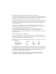
ISDN Service Ordering Information for the ADTRAN IQ Probe With ISDN Dial Backup For ADTRAN IQ Probe ISDN dial backup applications, the following guide can be used as an aid in ordering basic ISDN service from your local telephone company. The ADTRAN IQ Probe ISDN includes NT1 and Terminal adapter functionality and supports data rates up to 128 kbps.
Turn the Following Features Off: Packet Mode Data Multi-line Hunt Multiple Call Appearances Electronic Key Telephone Sets (EKTS) Shared Dictionary Numbers Accept Special Type of Number Intercom Groups Network Resource Selector (Modem Pools) Message Waiting Hunting InterLata Competition For service offered from a Northern Telecom DMS-100, request a Point-to-Point Multi-Point line with the following features: Line Type: Basic Rate, Functional Electronic Key Telephone Sets (EKTS): No Call Appearance Handling (
Table of Contents
Table of Contents Table of Contents Chapter 1. Introduction Product overview ................................................................................................................... 1 Understanding Frame Relay ................................................................................................. 2 SNMP Management ............................................................................................................... 3 Network Manager ............................................
Table of Contents Numeric Keypad .................................................................................................... 14 Next, Prev, Add, Delete ......................................................................................... 14 Shift .......................................................................................................................... 14 LED Descriptions ...................................................................................................
Table of Contents Chapter 6. DTE Port Configuration Physical Layer Options (PHYS LYR OPTS) ............................................................... 44 Interface Type ......................................................................................................... 44 Flow Control ........................................................................................................... 44 None ....................................................................................................
Table of Contents Management DLCI 1 and 2 Mode (DLCI 1 and 2 MODE) ...................................... 52 Maximum PVC Count (MAX PVC COUNT) ............................................................ 53 History Interval Count (HIST INT COUNT) ............................................................. 53 PVC Options (PVC CONFIG) ...................................................................................... 53 DLCI ...............................................................................
Table of Contents SPID 1/2 ........................................................................................................... LDN 1/2 ........................................................................................................... DCE Options ........................................................................................................... Interface Type .................................................................................................. DBU Bit Rate .............
Table of Contents V=View by Day/View by Interval ............................................................... 72 DTE Port Statistics ......................................................................................................... 73 DCE Port Statistics ......................................................................................................... 76 DBU Port Statistics ........................................................................................................
Table of Contents List of Tables Table 4-A Example Settings for Dial Backup Options ................................................. 36 Table 4-B Example Settings for PVC Configuration Table ......................................... 36 Table A-A Pin Assignments for 10baseT Connector ................................................... 107 Table A-B Pin Assignments for Control Connector .................................................... 108 Table A-C EIA-232 Connector Pin Assignments .....................
Table of Contents Figure 10-5 DCE Port Statistics (View by Day) ................................................................ 79 Figure 10-6 DBU Port Statistics (View by Interval) ......................................................... 83 Figure 10-7 DBU Port Statistics (View by Day) ............................................................... 84 Figure 10-8 DLCI Statistics for a Specific DLCI (View by Interval) ..............................
Chapter 1. Introduction Chapter 1 Introduction PRODUCT OVERVIEW The ADTRAN IQ Probe provides the visibility and control needed for both the physical and logical connections made in frame relay networks. The IQ Probe provides logical layer monitoring and management for frame relay. Each permanent virtual circuit (PVC) accessed through an IQ Probe is managed end-to-end as if it were a leased line connection.
Chapter 1. Introduction information rates (CIRs), and excess burst rates on each PVC • True non-intrusive, in-band transmission of statistics • Embedded SNMP and TELNET through the DTE, DCE, or SLIP/PPP port • Embedded SNMP and TELNET access available through the integrated 10baseT ethernet port • Control port provides SLIP and async PPP access to SNMP or VT 100 terminal configuration • Dial backup (DBU) available with ESP DBU cards; options include 4-wire Switched 56 (SW56), V.
Chapter 1. Introduction This header information contains a virtual circuit address known as a DLCI (data link connection identifier). The header information also contains bits used for network congestion control. Frame relay virtual circuits may be defined as permanent (PVC) or switched (SVC). PVCs have the same DLCI for a given path each time a user protocol session is established. The network service provider assigns these DLCIs at subscription time.
Chapter 1. Introduction Agent Control program that resides in each connected network device. This program responds to queries and commands from the network manager and returns requested information or invokes configuration changes initiated by the manager. MIB Index to the organized data within a network device. It defines the operation parameters that can be controlled or monitored. TELNET TELNET provides a password-protected, remote login facility to the IQ Probe.
Chapter 1. Introduction ESP CARD OPTIONS 4-Wire Switched 56 DBU Card This dial-up 4-wire SW56 DBU card allows you to pay for data connection only for the time the unit is active. The regional operating companies provide the 4-wire local loop service to SW56 customers. This card is compatible with AT&T Accunet and Sprint SW56 type services. V.34 DBU Card This module backs up the leased line application at data rates up to 33.6 kbps over an ordinary telephone network.
Chapter 1. Introduction WARRANTY AND CUSTOMER SERVICE ADTRAN will replace or repair this product within five years from the date of shipment if it does not meet its published specifications or fails while in service. For detailed warranty, repair, and return information refer to the ADTRAN Equipment Warranty and Repair and Return Policy Procedure. Return Material Authorization (RMA) is required prior to returning equipment to ADTRAN.
Chapter 2. Installation Chapter 2 Installation UNPACK, INSPECT, POWER UP Receipt Inspection Carefully inspect the IQ Probe for any shipping damage. If damage is suspected, file a claim immediately with the carrier and contact ADTRAN Customer Service. If possible, keep the original shipping container for use in shipping the IQ Probe for repair or for verification of damage during shipment.
Chapter 2. Installation The ADTRAN IQ Probe MIB is available from ADTRAN in the support section of the ADTRAN Web page at www.adtran.com. The following items are included in ADTRAN shipments of ESP DBU cards: • ESP DBU card • An 8-position modular to 8-position modular cable for the 4wire SW56 and ISDN DBU options or an 8-position modular to 4-position modular cable for the V.34 DBU option Customer Provides You must provide male interface cables for the DTE and DCE ports.
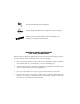
Chapter 2. Installation REAR PANEL Connectors for the IQ Probe are located on the rear panel. The DTE and DCE connectors provide DTE DB-25 interfaces. These connectors can be cabled to V.35 or X.21 interfaces (using optional ADTRAN adapter cables) or to an EIA-232 or EIA-530 interface (using a standard DB-25 cable). Part numbers for the optional cables follow: DB-25 to V.35 male adapter cable: 1200281L1 DB-25 to V.35 female adapter cable: 1200285L1 DB-25 to female DB-15 (X.
Chapter 2. Installation V.34, ISDN, 4-Wire Switched 56 LAN Switched Network DBU Modular Cable 10baseT Ethernet Cable DBU INTERFACE LAN 10 BASE-T DBU TELCO 90 - 240 VAC 50 / 60HZ ON DCE DTE OFF CONTROL DSU/CSU 1 2 4 7 COPY 3 5 ALARM 8 HOM E 0 RJ45-to-DB25 Cable Standard DB25 Cables (EIA-232 or EIA530) or ADTRAN Adaptor Cables (X.21 or V.
Chapter 2. Installation DBU Interface Card Slot The IQ Probe rear panel has one card slot (labeled DBU INTERFACE) for the installation of dial backup and DCE cards. To insert cards, perform the following procedure: 1. Remove power from the IQ Probe. 2. Slide the card into the DBU Interface rear slot until the card panel is flush with the IQ Probe chassis. 3. Push card locks in (until they click) to secure the card and ensure proper installation.
Chapter 2. Installation To prevent possible radio frequency interference emissions, a shielded cable is required. LAN 10baseT Interface This port is an 8-pin modular connector that provides a 10baseT ethernet local area network (LAN) interface. This LAN interface is used for SNMP and TELNET control. Control Port The IQ Probe has an 8-pin modular jack labeled CONTROL.
Chapter 3. Operation Chapter 3 Operation FRONT PANEL The IQ Probe faceplate is shown in Figure 3-1. Descriptions of each part of the front panel follow. LCD Window Displays menu items and messages in 2 lines by 16 characters. Enter Selects active menu items. To activate a menu item, scroll to it using the arrow keys or press the number of the item. The flashing cursor indicates the active parameter. Press Enter to select the active menu item.
Chapter 3. Operation Quick Key Pressing the Quick key returns the front panel to the Main menu. Numeric Keypad The numeric keypad contains the numbers 0 through 9 and alpha characters A through F, which are used to activate menu items and enter information such as the IP address. Next, Prev, Add, Delete To activate these functions, press and release the Shift key, then press the Next, Prev, Add, or Delete key. Use these keys when editing tables such as the PVC Configuration table.
Chapter 3.
Chapter 3.
Chapter 3. Operation LED Descriptions The IQ Probe has seven LED indicators: RS, CS, TD, RD, CD, TR, and ALM. These LEDs are identified as follows: RS: Request to Send Reflects the status of the RS pin of the DTE/DCE interface. CS: Clear to Send Reflects the status of the CS pin of the DTE/DCE interface. TD: Transmit Data This LED is active when the IQ Probe DTE/DCE port is transmitting data. RD: Receive Data This LED is active when the IQ Probe DTE/DCE port is receiving data.
Chapter 3. Operation Front Panel Operation To choose a menu item, press the corresponding number or alpha character on the keypad. Press Shift to activate menu items with alpha selections. Scrolling to the selection by pressing the up and down arrows also activates the menu items. The flashing cursor indicates the active selection. Press Enter to select the item. The following steps and Figure 3-2 illustrate how to select IQ Probe options: 1.
Chapter 3. Operation VT 100 Terminal Connection and Operation To control the IQ Probe using a VT 100 terminal, follow this procedure: 1. Set the IQ Probe baud rate to match the terminal through the front panel (maximum rate is 38.4k). Select 1 CONFIG, then 4 CONTROL PORT. 2. Using the ADTRAN-provided VT 100 terminal adapter, connect the COM port of a VT 100 compatible terminal or equivalent to the eight-pin modular jack labeled CONTROL on the rear of the IQ Probe.
Chapter 3. Operation In the upper right-hand corner of the VT 100 screen, LOCAL or REMOTE is displayed, indicating which unit the current screen represents. See Figure 3-3.
Chapter 3. Operation Figure 3-4 Terminal Main Menu IQ PROBE MENU STRUCTURE The opening menu is the access point to all other operations. The Main menu branches are Configuration, View Statistics, Test, Dial, and Logout. See Figure 3-4. Each Main menu item has several functions and submenus to identify and access specific parameters. The Logout selection is only available on the terminal interface. The Dial selection is only available when an ESP DBU card is installed.
Chapter 3. Operation Main Menu Definitions for the branches of the Main menu follow: Configuration (CONFIG) Configuration is used to select DTE, DCE, dial backup, and system operating parameters. For more information on configuration options, see the following chapters: Configuration Overview, DTE Port Configuration, Configuring the DCE Port, Configuring Dial Backup Options, and System Configuration.
D s of the e DTE/ ector. Chapter 3. Operation TD LED Active when the DTE/DCE port transmits data. Up and Down Arrows Scroll through and activate the submenu items available in the current menu. The flashing cursor indicates the active parameter. Enter Key Selects active menu item. RD LED Active when the DTE/DCE port receives data. Numeric Keypad Activates menu items and enters numerical information. IQ PROBE ENTER of the LCD Window Displays menu items and messages in 2 lines by 16 characters.
Chapter 3.
Chapter 4. Applications Chapter 4 Applications This chapter provides examples of some common IQ Probe management options as well as an example of a dial backup application. The management application examples include VT 100 management, out-of-band SNMP/TELNET management, and in-band PVC SNMP/TELNET management. Descriptions and configuration tips for these options are provided in the sections that follow. The application drawings in this chapter show routers as the frame relay device.
Chapter 4. Applications Local VT 100 Terminal Management Connect a VT 100 terminal to the IQ Probe CONTROL port. This interface provides full-screen configuration and all-inclusive statistics access. VT 100 management also allows for remote configuration. Through this port, a remotely located ADTRAN IQ device is fully accessible for configuration, diagnostics, and statistics viewing. Figure 4-1 gives an example of a VT 100 application. VT 100 remote mode is proprietary and non-intrusive.
Chapter 4. Applications Control Port Mode Set the Control Port Mode for TERMINAL (which is the default setting). This selection is found in the SYSTEM portion of the CONFIGURATION menu (SYSTEM -> CONTROL PORT OPTIONS -> CONTROL PORT MODE). Out-of-Band Management This management option (shown in Figure 4-2) is commonly used in situations where the customer is trying to reduce the amount of management traffic flowing through the frame relay device.
Chapter 4.
Chapter 4. Applications Gateway IP Address (if required) Enter the Gateway node IP address. This address is applicable only if the IQ Probe and the network manager are connected through a Gateway node. This address is available from the network administrator. The next five settings are applicable for SNMP access only: Read Community Set the Read Community name to match the NMS (network management system) settings. Write Community Set the Write Community name to match the NMS settings.
Chapter 4. Applications All PVC-based in-band management traffic must be noncompressed IP and use RFC 1490 encapsulation. Local PVC Management Local PVC management refers to a PVC created between the IQ Probe and the frame relay router on the DTE interface of the IQ Probe. This type of management is ideal when local management is needed but an ethernet connection is not available. To support this type of management, all traffic on the selected PVC must be RFC 1490 encapsulated, noncompressed IP traffic.
Chapter 4.
Chapter 4. Applications Write Community Set the Write Community name to match the NMS settings. Trap Manager DLCI Identify the virtual circuit used for all traps generated by the IQ Probe. This selection is found under TRAP MGR OPTIONS in the SYSTEM portion of the CONFIGURATION menu. Trap Manager IP Address Enter the IP address of the SNMP manager to which the IQ Probe sends traps. This selection is found under TRAP MGR OPTIONS in the SYSTEM portion of the CONFIGURATION menu.
Chapter 4. Applications Since the unit is set up for shared PVC management, all management traffic will be intercepted prior to reaching the remote router.
Chapter 4. Applications SHARED if the DLCI is used to carry customer traffic as well as management data. This option is found in the DCE Port Configuration menu. The IQ Probe unit supports management from two network DLCIs either shared or dedicated. The next five settings are applicable for SNMP access only: Read Community Set the Read Community name to match the NMS settings. Write Community Set the Write Community name to match the NMS settings.
Chapter 4. Applications traffic, and it also acts as a fire-wall that restricts management data to the IQ Probe. Dedicated PVC management is also ideal when the user wants to guarantee access to a remote IQ Probe regardless of the state of the remote LAN.
Chapter 4. Applications During dial backup, the IQ device receiving the call continues to use the frame relay circuit for PVCs that are not affected by the outage, while using the DBU interface for PVCs that are inactive due to the outage. This is done (without the attached DTE device's intervention) by modifying the status of PVCs that are in DBU state to active when the PVC status is given to the DTE.
Chapter 4. Applications See Figure 4-6 for an example of a dial backup application. Tables 4-A and 4-B provide example setups for the DBU Options (CONFIG ->DIAL BACKUP) and the PVC Configuration Table (CONFIG ->DCE PORT ->PVC CONFIG). The tables are based on the example application shown in Figure 4-6. Please note that the configuration selections given may need modification based on your network configuration.
Chapter 4. Applications Table 4-A Example Settings for Dial Backup Options Enable AUTO DBU WITH CARRIER DETECT LOSS Disable WITH NO LMI Enable FAIL TIMER 10 seconds RESTORE TIMER 1 minute REDIAL COUNTER 5 WAIT TO REDIAL 15 seconds PHONE NUMBERS Enter phone number to reach far end.
Chapter 5. Configuration Overview Chapter 5 Configuration Overview LOCAL AND REMOTE CONFIGURATION The IQ Probe can be configured locally, or communications can be established so that a local IQ Probe can configure a remote IQ Probe using a VT 100 interface. See the chapter Operation for information on selecting Local or Remote operation.
Chapter 5. Configuration Overview Configuration menu trees are shown in Figures 5-2 (for the terminal) and 5-3 (for the front panel interface).
Chapter 5.
Chapter 5.
Chapter 5.
Chapter 5.
Chapter 5. Configuration Overview 1 X.21 2 V.
Chapter 5.
Chapter 5. Configuration Overview 1 INTERFACE X.21 V.35 EIA-530 EIA-232 2 FLOW CONTROL 3 CTS OPTION FORCED ON FOLLOW RTS 4 DSR OPTION 5 CD OPTION FORCED ON NORMAL 6 TC CLOCK OPT NORMAL INVERTED NONE HARDWARE FECN/BECN 1 PHYS LYR OPTS PORT 2 FR OPTS 1 T392 2 N392 3 N393 4 MGMT DLCI 5 MGMT PVC OPT ENABLED DISABLED 1 INTERFACE 6 SIG RESPONSES ALWAYS ON FOLLOW NET 1 PHYS LYR OPTS 2 RATE (Kbps) 2 3 4 5 6 7 8 9 1 SIGNAL 2 T391 3 N391 4 N392 5 N393 X.21 V.
Chapter 5.
Chapter 6. DTE Port Configuration Chapter 6 DTE Port Configuration Configure the physical layer and frame relay protocol options for the DTE port located on the rear of the IQ Probe by selecting DTE PORT from the Configuration menu. Figure 6-1 illustrates the terminal Configuration menu for the DTE Port. The menu tree in Figure 6-2 shows the choices available in this menu.
Chapter 6. DTE Port Configuration In this chapter, the terminal selections are listed first followed by the Front Panel selections in parenthesis (if the names differ). 1 INTERFACE TYPE 2 FLOW CONTROL 1 X.21 2 V.
Chapter 6. DTE Port Configuration None No flow control is used and the IQ Probe drops frames during severe congestion while in DBU operation. Hardware The IQ Probe varies the DTE TC clock as necessary to relieve congestion during DBU operation. FECN/BECN While in a congested state during DBU operation, frames across the DBU PVCs have FECN or BECN set depending on the direction. Frames outbound to the network have FECN set, while frames inbound to the attached DTE device have BECN set.
Chapter 6. DTE Port Configuration Forced On The CD lead is always on. Normal The CD lead is off when the IQ Probe does not receive CD from the DSU/CSU on the DCE port. TC Clock Option (TC CLOCK OPT) Normal Clock for DTE's transmit data normal phase. Inverted Clock for DTE's transmit data inverted phase. May be used in high speed circuits (>512 kbps) when the DTE's V.35 interface has high delay. This is usually indicated by HDLC errors on the IQ Probe's DTE port.
Chapter 6. DTE Port Configuration For example: If N392=3 and N393=4, then if three errors occur within any four events, the interface is determined inactive. The status of the connection can be viewed in the Status menu under DTE Port Signaling State. The status will return to active once the threshold is no longer exceeded. Management DLCI (MGMT DLCI) To use local PVC management, enter the management data link connection identifier (DLCI).
Chapter 6. DTE Port Configuration Follows Network (FOLLOW NET) If ENABLED, PVC signaling responses are sent to the router only when the network signaling state is up. Enable this option when the router is going to use an alternate path for dial backup.
Chapter 7. Configuring the DCE Port Chapter 7 Configuring the DCE Port DCE PORT Access the DCE port menus by selecting DCE PORT from the Configuration menu. Full menu trees for the DCE Configuration selections are shown in Figures 5-2 (Terminal Configuration Menu Tree) and 5-3 (Front Panel Configuration Menu Tree) of the Configuration Overview chapter. The DCE port terminates the user end of the frame relay UNI interface.
Chapter 7. Configuring the DCE Port Figure 7-1 Terminal DCE Port Configuration Menu Physical Layer Options (PHYS LYR OPTS) The following sections describe the physical layer options available for the DCE port: Interface Type Select the DCE interface type. The choices are X.21, V.35, EIA530, and EIA-232. Serial Bit Rate (RATE ) Set the Serial Bit Rate to match the speed of the attached DSU/ CSU. The IQ Probe uses this information for statistical analysis.
Chapter 7. Configuring the DCE Port Frame Relay Options (FR OPTS) The terminal screen in Figure 7-2 appears when Frame Relay Options is selected from the DCE Port Configuration Menu. Figure 7-2 Terminal DCE Port Frame Relay Options Menu Signaling Type (SIGNAL) Set the signaling type option to match the DCE signaling type. Choices are none, LMI (gang of four), ANSI T1.617-D (Annex D), ITU-T Q.933-A (Annex A), or auto.
Chapter 7. Configuring the DCE Port N391 Determine how many link integrity polls occur in between full status polls. N392 and N393 These parameters define the error threshold for the UNI formed by the IQ Probe DCE port and the frame relay switch. If the error threshold is met, the signaling state status is changed to down, which indicates a service-affecting condition. This condition is cleared once N393 consecutive error-free events are received.
Chapter 7. Configuring the DCE Port Maximum PVC Count (MAX PVC COUNT) Sets the maximum number of PVCs that the IQ Probe will monitor for statistical information. This value determines the amount of history intervals available for storage. To get the maximum amount of statistical history storage, set this value equal to the number of PVCs assigned to the frame relay port. A smaller value increases history interval count but puts some of the PVC statistics into the unknown category.
Chapter 7. Configuring the DCE Port Only PVCs that are used in DBU should have the DBU DLCI set to a non-zero value. The range for the DBU DLCI field is from 16-1007. Therefore, you cannot manually enter 0 for the PVCs not used in DBU. When an entry is first created with the ADD selection, it is set to 0 by default. To reset a previously configured DBU DLCI to 0, delete the entry and then add it back in (using the Delete and Add selections/keys).
Chapter 7. Configuring the DCE Port Add (ADD key on front panel) Add a new entry to the PVC Options table. Delete (DELETE key on front panel) Delete the current entry in the PVC Options table.
Chapter 7.
Chapter 8. Configuring Dial Backup Options Chapter 8 Configuring Dial Backup Options DIAL BACKUP OPTIONS The Dial Backup Configuration menu (Figure 8-1) is available only when an optional ESP DBU card is installed in the IQ Probe. Use this menu to configure DBU options such as auto DBU capability, DBU criteria, DBU timer functions, and DBU phone numbers. See Figure 8-2 for a complete menu tree of the DBU selections. Figure 8-1 DBU Options Menu (with V.
Chapter 8. Configuring Dial Backup Options 1 AUTO DBU 2 DBU OPTIONS 3 DBU CRITERIA 1 CONFIG 3 DBU 4 DBU TIMERS 1 DISABLE 2 ENABLE 1 2 3 4 5 6 7 BEEPER OPTION PASSWORD OPT DBU PASSWORD DAILY LOCKOUT LOCKOUT START LOCKOUT END WEEKEND LOCK 1 WITH CARRIER DETECT LOSS 2 WITH NO LMI 1 2 3 4 1 DISABLE 2 ENABLE 1 DISABLE 2 ENABLE 1 DISABLE 2 ENABLE 1 DISABLE 2 ENABLE FAIL TIMER RESTORE TIMER REDIAL COUNTER WAIT TO REDIAL With V.
Chapter 8. Configuring Dial Backup Options In this chapter, the terminal selections are listed first followed by the Front Panel selections in parenthesis (if the names differ). Auto DBU The AUTOMATIC DBU option specifies whether the unit automatically enters dial backup mode or waits for manual setup. The factory default setting is DISABLE. DBU Options Beeper Option (BEEP OPTION) If enabled, the IQ Probe issues an intermittent beep while in dial backup.
Chapter 8. Configuring Dial Backup Options Lockout End Enter the hour that the daily lockout ends and dial backup is reactivated (0 to 23). This setting only applies if the DAILY LOCKOUT parameter is enabled. Weekend Lock If enabled, no backup will occur from midnight Friday to midnight Sunday. DBU Criteria With Carrier Detect Loss (WITH DCD LOSS) When enabled, the IQ Probe enters backup mode when a loss of carrier detect signal is detected on the DCE port. The factory default setting is ENABLE.
Chapter 8. Configuring Dial Backup Options IQ Probe encounters a busy or reorder, it attempts to establish the call the specified number of times. The factory default setting is 5. Wait to Redial (REDIAL DELAY) This option works in conjunction with the preceding Redial Counter. It selects the amount of time between redial attempts to connect the backup line. The amount of time, which is manually entered, can be up to 99 seconds. The factory default setting is 15 seconds.
Chapter 8. Configuring Dial Backup Options B-Channel Bit Rate (B-CH BIT RATE) Select the channel bit rate for the ISDN service. Select 64k unless your service only provides 56k. Number of B-Channels (NUM B-CHANNELS) Select the number of B-channels supported by the ISDN service. Select 2 if bonding is used. SPID 1/2 For ISDN dial backup, enter the service profile identifier (SPID) for both B-channels.
Chapter 9. System Configuration Chapter 9 System Configuration Access System configuration selections by first choosing CONFIGURATION from the Main menu. Then choose SYSTEM from the Configuration menu. Full menu trees for the System configuration selections are shown in Figures 5-2 (Terminal Configuration Menu Tree) and 5-3 (Front Panel Configuration Menu Tree). The Terminal System configuration menu is shown in Figure 9-1.
Chapter 9. System Configuration Subnet Mask Enter the subnet mask assigned to the LAN that the LAN 10baseT port is attached to. Figure 9-1 System Configuration Menu Gateway IP Addr (GW IP ADDRESS) Enter the Gateway IP address. The gateway is used when an ethernet packet is transmitted from the IQ Probe to a foreign subnet. Control Port Options (CTRL PORT OPTS) Control Port Mode (CTRL PORT MODE) Set the Control port for terminal, SLIP protocol, or PPP protocol mode.
Chapter 9. System Configuration Changing this option causes a complete system configuration and unit reset. Read Community (RD COMMUNITY) Enter the authentication strings used for SNMP management. Match the IQ Probe to the SNMP manager for read privileges. If using front panel entry, see the section Entering Letters Using the Front Panel in this chapter for more information. Write Community (WR COMMUNITY) Enter the authentication strings used for SNMP management.
Chapter 9. System Configuration Next (NEXT key on front panel) Edit the next entry in the Trap Manager Options table. Previous (PREV key on front panel) Edit the previous entry in the Trap Manager Options table. Add (ADD key on front panel) Add a new entry to the Trap Manager Options table. Delete (DELETE key on front panel) Delete the current entry in the Trap Manager Options table. System Time/Date Set the current hour, minute, day, month, and year.
Chapter 9. System Configuration ENTERING LETTERS USING THE FRONT PANEL Configuring the Read/Write Community names requires the entry of letters rather than numbers. When configuring the unit using the front panel, special steps must be taken in order to perform these entries. The following example of entering the Write Community name illustrates this procedure: 1. 2. 3. 4. 5. 61200214L1-1 Select WRITE COMMUNITY from the System configuration menu. Press the up arrow to scroll to the desired character.
Chapter 9.
Chapter 10. Statistics Chapter 10 Statistics For descriptions of the terminal statistics menus, see the following section, Viewing Statistical Information (Terminal Interface). For front panel menu descriptions, see the section Viewing Statistical Information (Front Panel Interface). VIEWING STATISTICAL INFORMATION (TERMINAL INTERFACE) Select View Statistics from the Main menu to access the View Statistics Menu shown in Figure 10-1.
Chapter 10. Statistics Figure 10-1 View Statistics Menu Terminal Statistics Display Options DTE port, DCE port, DBU port, and DLCI statistics are given in two formats: View by Interval and View by Day. View by Interval In this view, the first column is a running total for the current day. All other columns are grouped into user-configured time frames with the most recent information displayed on the left.
Chapter 10. Statistics To configure the interval time frame, go to the System Configuration menu under History Interval Size and select the time you want the history interval to be set for (from 5 to 30 minutes, in five minute intervals). The IQ Probe gathers and displays the information according to the time selected. The IQ Probe cuts the first gathering session short in order to begin falling on the selected time boundary.
Chapter 10. Statistics Hot Keys Once you have entered one of the statistics menus, hot keys are displayed across the bottom of the screen, allowing you to quickly access other menus or navigate within the current menu. These keys vary depending on the menu currently displayed. ESC=Menu Press the ESC key to return to the main View Statistics menu (shown in Figure 10-1). D=DLCI When viewing DCE port statistics, press D to view the DLCI Statistics menu shown in Figure 10-8.
Chapter 10. Statistics The following sections describe the information given on the DTE port, DCE port, DBU port, DLCI, and System Statistics menus. DTE Port Statistics Information given is for the DTE port since the last reset. See Figures 10-2 and 10-3 for the two DTE Port Statistics screen formats. Leads On If a lead is active on the selected port, it is listed in the View Statistics menu. See Figure 10-2.
Chapter 10. Statistics Figure 10-3 DTE Port Statistics (View by Day) Interval Remaining Number of seconds remaining in the current timed interval. This field is only shown in View by Interval menus. Signaling State Indicates if the frame relay signaling state is currently up or down. Local PVC Rx Frames Total frames received by the DTE port across the local management PVC. Local PVC Rx Bytes Total bytes received by the DTE port across the local management PVC.
Chapter 10. Statistics Local PVC Tx Bytes Total bytes transmitted by the DTE port across the local management PVC. Signal Down Time Time in seconds the signaling state is down. Signal Error Number of signal frames received with PVC signaling protocol violations. Signal Timeouts Number of T392 timeouts that have occurred. Signal State Change Number of changes in the signaling protocol state. Rx Full Status Number of full status polls received on the DTE side.
Chapter 10. Statistics Octet Align Number of frames received with a bit count that does not fall on 8-bit boundaries. This transmission error is also reflected in the Discard Frame field. Length Error Number of frames received with fewer than 5 octets or greater than 4500 octets. This link violation is also reflected in the Discard Frame field. EA Violation Number of frames received with an error in the extended address (EA) bit field of the frame relay header.
Chapter 10. Statistics Interval Remaining Number of seconds remaining in the current timed interval. This field is only shown in View by Interval menus. DBU State Current state of the DBU circuit. This field is only shown if an ESP DBU card is installed. Rx Frames Number of frames received by the DCE port. Rx Bytes Number of bytes received by the DCE port. Maximum Rx Throughput Maximum throughput sample in the receive direction for the given interval. This is displayed in kbps.
Chapter 10. Statistics Figure 10-4 DCE Port Statistics with DBU Card Installed (View by Interval) Maximum Tx Throughput Maximum throughput sample in the transmit direction for the given interval. This is displayed in kbps. Average Tx Throughput Average throughput in the transmit direction for the given interval. This is displayed in kbps. Maximum Tx Utilization Maximum utilization sample in the transmit direction for the given interval.
Chapter 10. Statistics Figure 10-5 DCE Port Statistics (View by Day) Port UA Time Time in seconds the DCE port is unavailable for data delivery. This means that the data link is down or in test, or that the frame relay signaling state is down. Signal Down Time Time in seconds the signaling state has been down. Signal Error Number of signal frames received with PVC signaling protocol violations. Signal Timeouts Number of T391 timeouts that have occurred.
Chapter 10. Statistics Rx Full Status Number of full status responses received on the DCE side. Tx Full Status Number of full status polls transmitted by the IQ Probe. Rx LI Only Number of link integrity (LI) only responses received on the DCE side. Tx LI Only Number of link integrity polls transmitted by the IQ Probe. Async Status Number of asynchronous status messages received by the IQ Probe.
Chapter 10. Statistics Length Error Number of frames received with fewer than 5 octets or greater than 4500 octets. This link violation is also reflected in the Discard Frame field. EA Violation Number of frames received with an error in the extended address (EA) bit field of the frame relay header. Encapsulation Error Number of frames received on a dedicated management DLCI that have RFC 1490 errors. These errors are also reflected in the Discard Frames field.
Chapter 10. Statistics DBU State Current state of the DBU circuit. Interval Remaining Number of seconds remaining in the current timed interval. This field is only shown in View by Interval menus. Rx Frames Number of frames received by the DBU port. Rx Bytes Number of bytes received by the DBU port. Maximum Rx Throughput Maximum throughput sample in the receive direction for the given interval. This is displayed in kbps.
Chapter 10. Statistics Average Tx Throughput Average throughput in the transmit direction for the given interval. This is displayed in kbps. Maximum Tx Utilization Maximum utilization sample in the transmit direction for the given interval. Utilization is displayed as a percent of DBU port bandwidth. Average Tx Utilization Average utilization sample in the transmit direction for the given interval. Utilization is displayed as a percent of DBU port bandwidth.
Chapter 10. Statistics frames received on the dedicated management DLCI, transmission errors, or link violations. Aborts Number of frames received without a closing flag. This transmission error is also reflected in the Discard Frame field. CRC Errors Number of frames received with CRC violations. This transmission error is also reflected in the Discard Frame field. Octet Align Number of frames received with a bit count that does not fall on 8-bit boundaries.
Chapter 10. Statistics Length Error Number of frames received with fewer than 5 octets or greater than 4500 octets. This link violation is also reflected in the Discard Frame field. Encapsulation Error Number of frames received on a dedicated management DLCI that have RFC 1490 errors. These errors are also reflected in the Discard Frames field. If both management DLCIs are shared, the Encapsulation Error field is N/A.
Chapter 10. Statistics Figure 10-8 DLCI Statistics for a Specific DLCI (View by Interval) DLCI Statistics for a Specific DLCI Throughput (Tx and Rx) Displays the current throughput sample for this PVC. This is displayed in kbps. Utilization (Tx and Rx) Displays the current CIR utilization sample for this PVC. Remaining Number of seconds remaining in the current timed interval. Rx Frames Number of frames received by the DCE port on the specified DLCI.
Chapter 10. Statistics Maximum Rx Throughput Maximum throughput sample in the receive direction for the given interval. This is displayed in kbps. Average Rx Throughput Average throughput in the receive direction for the given interval. This is displayed in kbps. Maximum Rx Utilization Maximum utilization sample in the receive direction for the given interval. Utilization is displayed as a percentage of CIR. Average Rx Utilization Average utilization in the receive direction for the given interval.
Chapter 10. Statistics Average Tx Utilization Average utilization sample in the transmit direction for the given interval. Utilization is displayed as a percentage of CIR. Time in DBU Time (in seconds) that the specified DLCI is in DBU mode. PVC IA Time Time in seconds that the PVC is in the inactive state. Rx FECN Number of frames received on the DCE port over the specified DLCI with the FECN bit of the frame relay header enabled.
Chapter 10. Statistics Tx CR Number of frames transmitted from the DCE port over the specified DLCI with the CR bit of the frame relay header enabled. Lost Frames Number of frames lost across the PVC. This field is applicable only if the DCE port's Sequence Number Checking option (accessed through the DCE Port Configuration menu) is ENABLED. Remote Lost Frames Number of lost frames reported by the remote IQ device.
Chapter 10. Statistics Average Tx Frame Average size of frames transmitted across the DLCI. Minimum Frame Delay Minimum round trip delay of the DLCI. This field is applicable only if the DCE port's PVC Delay Measurement option (accessed through the DCE Port Configuration menu) is ENABLED. Maximum Frame Delay Maximum round trip delay of the DLCI. This field is applicable only if the DCE port's PVC Delay Measurement option (accessed through the DCE Port Configuration menu) is ENABLED.
Chapter 10. Statistics DLCI List This menu lists all available DLCIs and classifies them as active (A), inactive (I), or unknown (U). See Figure 10-9. A byte and frame break out of each DLCI is also provided including an in/ out count and a count of how many frames were received with FECN, BECN, or DE enabled.
Chapter 10. Statistics Figure 10-10 System Statistics Screen VIEWING STATISTICAL INFORMATION (FRONT PANEL INTERFACE) Select STATS from the Main menu. From this menu, choose to view DTE, DCE, DBU, DLCI, or System statistics or to reset the statistics. Once a selection (other than Reset) is made, the first Statistics screen of that category appears. Scroll through the remaining screens using the arrow keys.
Chapter 10. Statistics RS TR CS CD SR request to send data terminal ready clear to send carrier detect data set ready RS TR CS CD * SR 1 * Figure 10-11 Control Signal Status Screen Signal State Current signaling state of DTE port (up or down). See Figure 1012. 1 SIGNAL STATE DOWN Figure 10-12 Signal State Screen Signal State Change Number of changes in the signaling protocol state. Signal Timeouts Total T392 timeouts that have occurred since the last reset.
Chapter 10. Statistics Signal Errors Total signal frames received with PVC signaling protocol violations. Errored Frames Total errored frames received since last reset. CRC Errors Number of frames received with CRC violations. Abort Frames Total frames received without a closing flag. Octet Align Number of frames received with a bit count that does not fall on 8-bit boundaries. Signal Down Time Time in seconds that signaling state has been down.
Chapter 10. Statistics Signal Timeouts Total T391 timeouts that have occurred since the last reset. Signal Errors Total signal frames received with PVC signaling protocol violations. Frames In Total received frames since last reset. Frames Out Total transmitted frames since last reset. Errored Frames Total errored frames received since last reset. CRC Errors Number of frames received with HDLC CRC violations. Abort Frames Total frames received without a closing flag.
Chapter 10. Statistics Frames In Total received frames since the unit went into dial backup mode (or since last reset). Frames Out Total transmitted frames since the unit went into dial backup mode (or since last reset). Errored Frames Total errored frames received since the unit went into dial backup mode (or since last reset). CRC Errors Number of frames received on the dial backup circuit with CRC violations. Abort Frames Total frames received on the dial backup circuit without a closing flag.
Chapter 10.
Chapter 10.
Chapter 11. Testing Chapter 11 Testing This menu allows you to perform diagnostics by initiating PVC loopback tests and ping tests. See Figure 11-1 for the terminal Test menu. See Figure 11-2 for the Front Panel menu tree.
Chapter 11. Testing 1 PVC LOOPBACK 3 TEST 2 PING 1 2 3 4 DLCI START TEST STOP TEST VIEW TEST 1 PING ADDRESS 2 START PING PINGS TX PINGS RX MIN RESP TIME MAX RESP TIME AVG RESP TIME FRAMES RX FRAMES TX MIN RESP TIME MAX RESP TIME AVG RESP TIME LOST FRAMES RMT LOST FRAMES Figure 11-2 Front Panel Test Menu In this chapter, the terminal selections are listed first followed by the Front Panel selections in parenthesis (if the names differ).
Chapter 11. Testing Figure 11-3 PVC Loopback Menu DLCI <0 = all> (DLCI) Enter the DLCI of the PVC to be tested (or enter 0 to test all available PVCs). Test Length Amount of time (in minutes) that you want the test to take place. Enter 0 for a continuous test. This option is not available on the front panel. Start Test Starts the test. Stop Test Ends the test in progress prematurely or terminates a continuous test.
Chapter 11. Testing View Test Displays the Test Statistics menu shown in Figure 11-4. Descriptions of each field in the Test Statistics menu follow: PVC Active/Inactive/Undefined Displays current state of the selected PVC as determined by the switch (only available in the terminal menu). • Active: The PVC is currently operational. • Inactive: There is currently a physical or frame relay layer problem at the remote end of the PVC, or a problem exists inside the frame relay cloud for the selected PVC.
Chapter 11. Testing Average Loop Response Time (AVG RESP TIME) Average round-trip time (in seconds) for the current test. Figure 11-4 Test Status Screen Reset Test Stats Resets the information shown in the Test Statistics menu (only available in the terminal menu). View DLCI List See the section DLCI List in the chapter Statistics for a description of this menu (only available in the terminal menu).
Chapter 11. Testing Ping Select PING to send a ping request to a specific address. Ping testing is only available when the ethernet port is enabled (CONFIG -> SYSTEM -> ETHERNET PORT). Address to Ping (PING ADDRESS) Enter the IP address of the unit the IQ Probe is sending an echo request (ping) to. Start Ping The Start Ping command causes the IQ Probe to send ten ping requests to the target station. At the end of the ten-ping test, the following results are shown.
Chapter 12. Activating Dial Backup Options Chapter 12 Activating Dial Backup Options The dial backup options available from the Main menu (4=DIAL) appear in Figure 12-1. These options are only available when an ESP DBU card is installed. 1 DIAL BACKUP Dial Backup Idle 1 DIAL STORED # Select stored number. 2 STAY ON LEASED 2 ENTER DIAL # Enter number to dial.
Chapter 12. Activating Dial Backup Options Dial Options During Dial Backup Hang Up Terminates the dial backup connection and attempts to reestablish communication on the data line. Stay On Line This IQ Probe remains in dial backup mode and returns to the Statistics menu.
Appendix A. Pinouts Appendix A Pinouts The following tables give the pin assignments for the IQ Probe connectors, adapter cables, and card options. For more information, see the chapter Installation. Table A-A Pin Assignments for 10baseT Connector Pin 61200214L1-1 Name Description 1 TD+ The positive signal for the TD differential pair. This signal contains the serial output data stream transmitted onto the network. 2 TD- The negative signal for the TD differential pair (pins 1 and 2).
Appendix A. Pinouts Table A-B Pin Assignments for Control Connector RJ Pin# 1 2 3 4 5 6 7 8 Function GND RTS TD DSR RD CTS* DTR DCD Direction I I O O O I O *Used for hardware flow control.
Appendix A.
Appendix A. Pinouts Table A-E Pin Assignments for DB-25 to X.21 (DB-15) Adapter Cable 110 DB25 Pin# X.
Appendix A. Pinouts Table A-F Pin Assignments for DB-25 to V.35 Adapter Cable (Rear Panel Connector) 61200214L1-1 DB25 Pin# V.
Appendix A. Pinouts Table A-G Pin Assignments for DB-25 to V.35 Adapter Cable (DCE Card Option Connector) DB25 Pin# V.35 Pin# 1 2 3 4 5 6 7 8 9 10 11 12 13 14 15 16 17 18 19 20 21 22 23 24 25 112 A C D E B F AA Y V T R S P H W U X Function FGND TD(EIA-232) RD(EIA-232) RTS CTS DSR GND DCD NEG POS TC-B(V.35) TC-A(V.35) RC-A(V.35) RD-B(V.35) TC(EIA-232) RD-A(V.35) RC TD-B(V.35) TD-A(V.35) DTR ETC-B(V.35) ETC-A(V.35) ETC(EIA-232) RC-B(V.
Appendix A. Pinouts Table A-H Dial Backup Card Connectors Pin Name Description 4-wire Switched 56 1 R1 Transmit Data from DSU to Network-Ring 1 2 T1 Transmit Data from DSU to Network-Tip 1 3-6 Not Used 7 T Receive Data from Network to DSU-Tip 8 R Receive Data from Network to DSU-Ring V.
Appendix A.
Appendix B. Specifications Summary Appendix B Specifications Summary SPECIFICATIONS AND FEATURES This appendix provides the standard specifications and features of the IQ Probe. Operating Modes 100 DLCIs supported Frame relay using EIA-232, V.35, EIA-530, X.21 interface protocols DTE/DCE Data Rates Frame relay 56 kbps to 2.048 Mbps synchronous DTE/DCE Interface Standard DB-25 for EIA-530 and EIA-232 Adapter cable for V.35 and X.
Appendix B. Specifications Summary SLIP/PPP Port Interface Electrical: EIA-232 Physical: female DB-25 (provided female DB-25 adapter) Data rates: Async 9.6 to 38.
Acronyms and Abbreviations Acronyms and Abbreviations ACK ........................................................ acknowledgment ALM ........................................................ alarm ANSI ....................................................... American National Standards Institute ARP ......................................................... address resolution protocol ASCII ......................................................
Acronyms and Abbreviations DSU ......................................................... data service unit DTE ......................................................... data terminal equipment DTR ......................................................... data terminal ready EA ............................................................ extended address EBCDIC .................................................. extended binary coded decimal interexchange code ESP ............................................
Acronyms and Abbreviations RIP ........................................................... routing information protocol RMA ........................................................ return material authorization RS ............................................................ request to send; also recommended standard RTS .......................................................... request to send Rx ............................................................ receive SAP ......................................
Acronyms and Abbreviations 120 IQ Probe User Manual 61200214L1-1
Glossary Glossary ANSI American National Standards Institute. Devices and proposes recommendations for international communications standards. ASCII American National Standard Code for Information Interchange. The standard and predominant 7-bit (8-bit with parity) character code used for data communications and data processing. asynchronous A method of data transmission which allows characters to be sent at irregular intervals by preceding each character with a start bit, followed by a stop bit.
Glossary bit A binary digit. A signal, wave, or state is represented as either a binary 0 or 1. bits per second (bps) The number of bits passing a specific point per second. Examples of common rates are: • A Kilobit is one thousand bits per second (kbps) • A Megabit is one million bits per second (Mbps) bridge A device that supports LAN-to-LAN communications. Bridges may be equipped to provide frame relay support to the LAN devices they serve.
Glossary CIR committed information rate. Less than or equal to the access rate, the CIR is used by the service provider for rate enforcement when the network is congested. When rates exceed the CIR, frames may be discarded. clocking An oscillator-generated signal that provides a timing reference for a transmission link. A clock provides signals used in a transmission system to control the timing of certain functions.
Glossary office. A CSU regenerates digital signals. It monitors them for problems, and provides a way of testing the digital circuit. CTS clear to send. A signal on the DTE interface indicating that the DCE is clear to send data. dB The standard abbreviation for decibel. A decibel is a unit of measure for signal. A decibel is usually the relation between a transmitted signal and a standard signal source.
Glossary DSU data service unit. A device designed to transmit and receive digital data on digital transmission facilities. DTE data terminal equipment. The end-user terminal or computer that plugs into the termination point (DCE) of a communications circuit. The main difference between the DCE and the DTE is that pins two and three are reversed. encapsulation A process by which an interface device places an end device's protocol-specific frames inside a frame rely frame.
Glossary frame-relay-capable interface device A communications device that performs encapsulation. Frame-relay-capable routers and bridges are examples of interface devices used to interface the customer's equipment to frame relay network. See also interface device and encapsulation. frame relay frame A variable-length unit of data, in frame-relay format that is transmitted through a frame relay network as pure data. Contrast with packet.
Glossary IP internet protocol. A protocol which provides for transmitting blocks of data between hosts identified by fixed-length addresses. ISDN integrated services digital network. A network architecture that enables end-toend digital connections. The network supports diverse services through integrated access arrangements and defines a limited set of standard, multipurpose interfaces for equipment vendors, network providers, and customers.
Glossary packet-switching network A telecommunications network based on packet-switching technology, wherein a transmission channel is occupied only for the duration of the transmission of the packet. Contrast with frame relay network. parameter A numerical code that controls an aspect of terminal and/or network operation. Parameters control such aspects as page size, data transmission speed, and timing options.
Glossary strips the frame relay frame off of each frame to produce the original LAN frame, and passes the LAN frame on to the end device. Routers connect multiple LAN segments to each other or to a WAN. Routers route traffic on the Level 3 LAN protocol (e.g., the internet protocol address). See also bridge. SDLC synchronous data link control.
Glossary synchronizing bits (sync bits) A fixed pattern in synchronous transmission used to identify the boundaries of frames. synchronous Communications in which the timing is achieved by sharing a single clock. Each end of the transmission synchronizes itself with the use of clocks and information sent along with the transmitted data. TELNET The standard TCP/IP remote login protocol specified in RFC-854.
Index Index Symbols 10baseT LAN port 8, 9, 25 pin assignments 107 4-wire SW56 DBU card 5 A abort frames 94, 95 DBU port 96 aborts 75, 80, 84 activating menu items 13, 18 add 55, 66 ADD key 14, 15, 55, 66 address to ping 104 addressing 2 agent 4 alarm 17 ALM LED 17, 15 always on 47 Annex A 49, 51 Annex D 49, 51 ANSI 2 ANSI T1.
Index CIR 54 clear to send 17 clock setting 66 CONFIG 18, 22 configuration 18, 22 DCE port 49 DTE port 43 local 37 menus 38 front panel 41 terminal 39 remote 37 system 63–67 congestion 45 congestion control 3 control port 2, 8, 9, 10, 12, 19, 25 configuring 37 mode 26, 64 options 64 pin assignments 108 CR 88, 89 CRC errors 75, 80, 84, 94, 95 DBU port 96 CRC16 2 CS 17, 93, 94 CS LED 15 CTRL PORT MODE 64 CTRL PORT OPTS 64 CTS 73 CTS option 45 customer service 6, 7 D daily lockout 59 data rates 115 data termi
Index options activating 105–106 dial options during DBU 106 menu tree 105–106 with DBU idle 105 discard eligibility 88 discard frame 75, 80, 83 DLCI 3, 19, 23, 28, 47, 52, 53, 54, 75, 101, 115 1 and 2 52 1 and 2 MODE 52 statistics 72, 85, 86 specific DLCI 86 summary of all 91 DLCI list statistics front panel 96 DMS100 61 DSR 73 DSR option 45 DSR state change 80 DTE 9 port 2, 18 configuration 43–48 configuring 37 menu tree 44 statistics 73, 92 terminal configuration menu 43 statistics 69 DTE interface 10, 1
Index operation 18 full status 80 full status polls 75 G gateway IP address 27, 64 GW IP ADDRESS 64 H hang up 106 hardware flow control 45 header 2 HIS INT SIZE 66 HIST INT COUNT 53 history interval count 53 history interval size 66, 71 hot keys 72 I in-band 2 in-band management 27 inactive DLCI 76, 81 included in shipment ESP cards 8 IQ Probe 7 interface support 115 interface type 44, 50, 62 interval remaining 74, 77, 82 invalid DLCI 76, 81 IP address 26, 28, 29, 31, 47, 63 IQ View 2 ISDN 5 switch type
Index mode 52 management DLCI 1 and/or DLCI 2 31 management DLCI 1 and/or DLCI 2 mode 31 management options 23 management PVC option 47 MAX PVC COUNT 53 MAX RESP TIME 102 ping test 104 max response time ping test 104 maximum frame delay 90 maximum loop response time 102 maximum PVC count 53 maximum Rx frame 89 maximum Rx throughput 77, 82, 87 maximum Rx utilization 77, 82, 87 maximum Tx frame 89 maximum Tx throughput 78, 82, 87 maximum Tx utilization 78, 83, 87 menu items selecting 14 menu navigation 18 MGM
Index ping responses 104 ping tests 99 PINGS RX 104 pings transmitted 104 PINGS TX 104 pinouts 107 polling 49 port UA time 79, 95 power cord 10 power switch 10 power up 8 PPP 1, 8, 12, 25 PREV key 14, 15, 54, 66 previous 54, 66 product overview 1–2 provided by customer 8 PVC 1, 3, 4, 28, 30, 49, 53, 101 active/inactive/undefined 102 PVC CONFIG 53 PVC count 53 PVC delay 54 PVC inactive 88 PVC loopback 100 PVC loopback test 99 PVC options 14, 53 PVC state change 90 Q QUICK key 14, 15 R RATE 50 RD 17 RD COMM
Index in-band 23 out-of-band 23 specifications 115 SPID 62 SR 93, 94 start ping 104 start test PVC loopback test 101 statistics 1 DBU port 81 DCE port 76 DLCI 85 DTE port 73 system 91 view by day 74 view by interval 73 viewing 69 front panel 92 terminal 69 statistics menus changing view option 72 scrolling left and right 72 turning pages 72 STATS 22 stay on leased 105 stay on line 106 stop test PVC loopback test 101 subnet mask 26, 47, 64 SVC 3 SW56 DBU 5 switch type 61 system configuration 37, 63 statistic
Index utilization DLCI stats 86 V V.34 DBU card 5, 61 V.
Product Support Information Pre-Sales Inquiries and Applications Support Please contact your local distributor, ADTRAN Applications Engineering, or ADTRAN Sales: Applications Engineering Sales (800) 615-1176 (800) 827-0807 Post-Sale Support Please contact your local distributor first. If your local distributor cannot help, please contact ADTRAN Technical Support and have the unit serial number available.