
Network Device Specification Sheet

161190860L1-5B Section 61190860L1-5, Issue 2
CONTENTS
1. GENERAL ................................................................ 1
2. INSTALLATION ....................................................... 3
3. CONFIGURATION ...................................................4
4. OPERATIONAL DESCRIPTION ............................. 5
5. NORMAL OPERATION ........................................... 6
6. PROTECT OPERATION ........................................... 6
7. PROTECTION SWITCH ........................................... 8
8. SWITCHBACK ........................................................10
9. AUTO-PROTECT OPERATION ............................ 11
10. SPECIFICATIONS .................................................. 12
11. MAINTENANCE ..................................................... 12
12. WARRANTY AND CUSTOMER SERVICE ......... 12
Trademarks: Any brand names and product names included in this document are
trademarks, registered trademarks, or trade names of their respective holders.
1xN Remote Protection Switch
Pro-Cap
Installation and Maintenance
Section 61190860L1-5B
Issue 2, January 2002
CLEI Code: NCM5NTDD_ _
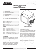
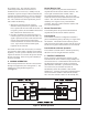
Figure 1. 1xN Pro-Cap
1. GENERAL
This practice provides installation and operational
procedures for the ADTRAN‚
Remote 1xN Pro-Cap
protection switch multi-mount housing (P/N
1190860L1). See Figure 1. Pro-Cap initiates remote
switching of a DS1 or HDSL circuit to a standby line
following detection of a fault. This eliminates the
immediate need for a vehicle dispatch to investigate
trouble or provide standby service. The shelf also
accommodates DDS and ISDN technologies but
without protection.
Pro-Cap can be used in conjunction with the
ADTRAN Total Access
®
3000 Carrier Class
Broadband Multiservice Access
Platform, or any standard Office Repeater Bay (ORB)
with T1 or HDSL to provide a Protection Switching
Network Interface (PSNI).
The Pro-Cap housing accepts eight T200 type circuit
cards or four dual slot T400 DS-1, HDSL, or HDSL2
circuit cards. The unit is a wall mounted assembly
that provides convenient access to CPE connections.
The assembly incorporates a circuit board backplane
that provides a choice of amphenol connector or
wire-wrap pins for facility wiring hook-up.
The Pro-Cap accepts -48 VDC local power or a
modular power supply that inserts into the POWER
slot at the far right of the shelf. The power supply
module includes an AC power cord that plugs into a
standard 110 VAC grounded outlet.
The Switch Customer Interface Module (SCIM) can
mount to either the left or right side of the Pro-Cap
housing to facilitate access to all CPE connections.
FIGURES
Figure 1. 1xN Pro-Cap....................................................1
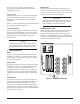
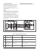
Figure 2. SCIM Card Elements ......................................4
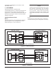
Figure 3. Normal Operation ...........................................6
Figure 4. Arming Operation ...........................................8
Figure 5. Protect Operation ..........................................10
Figure 6. Switchover..................................................... 10
Figure 7. Total Access 3000 Auto-protect Switching .. 11
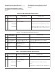
TABLES
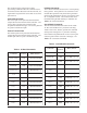
Table 1. LED Indication ................................................ 3
Table 2. In-Band Commmands ..................................... 7
Table 3. Out-Of-Band Commands ................................7
Table 4. In-Band Enable/Disable Protocol ................... 8
Table 5. In-Band Protection Switch Protocol ...............9
Table 6. Out-Of-Band Enable/Disable Protocol ........... 9
Table 7. Out-Of-Band Protection Switch Protocol ....... 9
Table 8. In-Band Protection Release Protocol ............11
Table 9. Out-Of-Band Protection Release Protocol ...11
Table 10. Specifications ................................................12