
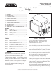
Network Device Specification Sheet

2 61190860L1-5BSection 61190860L1-5, Issue 2
The SCIM can be locally powered by -48 VDC, or
span powered from the standby unit in slot 8 if
equipped for span power. Slide switch S1 selects
between local or span power. CPE receive and
transmit connections are either amphenol or RJ-48C
jacks.
Revision History
Issue 2 adds Auto-Protect information when the
Pro-Cap is configured in a Total Access 3000 network.
Features
The 1xN Pro-Cap includes these features:
• Protection module.
• Compact and lightweight assembly that
accommodates eight T200 mechanics or four
T400 mechanics modules.
• Reversible SCIM for right side or left side
assembly.
• Prewired backplane to minimize wiring errors and
installation time.
• Protect module can function as standard channel
module.
• Dedicated slot for modular power supply.
• LEC facility connections are made by 25-pair
Amphenol XMT/RCV connectors or wire-wrap
pins.
• CPE connections are made to RJ-48C modular
jacks or 25-pair Amphenol XMT/RCV
connectors.
• Auto-Protect Switching with Total Access 3000
applications.
• Swing open tinted Plexiglas front cover.
• Available with key-locking metal cover (List 4
Option).
• Includes standard 10-year warranty.
Physical Description
The 1xN Pro-Cap consists of four elements:
1. Mounting-Plate
The mounting-plate attaches to a customer
premises backboard.
2. Shelf
The shelf has slots for seven channel modules,
one standby (protect) module, and one power
module, plus two external edge connectors for
the SCIM. The power terminal strip has
connections for power, alarm, and ground. The
shelf attaches to the mounting-plate.
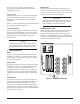
3. Switch Customer Interface Module
This module inserts into one of the SCIM edge
connectors located on either side of the shelf. It
has both amphenol and RJ-48C interface
connections to the customer loop. Behind an
access panel is a power connection terminal
strip, a slide switch for either span or local
power, protect ON/OFF switch, and a
pushbutton for selecting individual module
protection or resetting the protect configuration.
Selection and status is indicated with associated
LEDs on the SCIM front panel.
4. Housing Cover
The Plexiglas swing door housing cover
encloses the shelf allowing viewing and access
to the shelf modules.
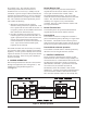
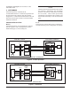
Functional Description
During normal customer and network transmission,
data is transported through the active modules in slots 1
through 7. The module in slot 8 is the standby
(protect) unit. If a fault is detected on an active line a
series of facility initiated manual commands switch the
standby module to an active mode in place of the
faulted unit. When the faulted unit malfunction is
resolved another series of manually initiated
commands (or the reset switch) returns it to active
service and the standby unit is returned to standby
status. The LED bank shows module status during
normal and standby conditions. When circuit
protection mode is disabled the Pro-Cap unit can be
used as a standard 8-slot T200 mounting.
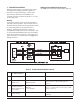
Auto-Protect Switching
When the Pro-Cap is used in association with the
ADTRAN Total Access 3000 platform, certain Total
Access 3000 cards initiate an automatic protect
function with the Pro-Cap. These cards send the same
protect enable/disable, arming, and switching codes as
sent in the manual switching mode. The Pro-Cap does
not require configuration changes to support the
auto-protect feature. The same configuration
supporting manual switching also supports automatic
switching. Additional information is in Section 9 of
this practice.
Listed here are Total Access 3000 cards that initiate the
auto-protect codes:
• H2TUC 1181112L5
• H2TUR 1222026L7
• H2TUR 1221026L7