AT&T AT&T System 25 Installation and Maintenance Manual 555-540-103 B November 1995
©1989 AT&T All Rights Reserved Printed in USA TO ORDER COPIES OF THIS DOCUMENT REFER TO DOCUMENT NUMBER 555-540-103 Contact: Your AT&T sales representative, or Call: 800-432-6600, Monday through Friday between 7:30 am and 6:00 pm EST, or In Canada call: 800-255-1242 Write: AT&T Customer Information Center 2855 North Franklin Road P.O. Box 19901 Indianapolis, Indiana 42619 Every effort was made to ensure that the information in this document was complete and accurate at the time of printing.
DANGER Do not open the fan assembly or remove rear cabinet cover before unplugging the cabinet from the electrical outlet. Wait at least five minutes after unplugging the power cord before removing the rear cover or power supply. The AT&T System 25 cabinets are not user serviceable. Some voltages inside the cabinets are hazardous. This equipment is to be serviced only by qualified technicians.
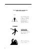
THE FOLLOWING SYMBOLS AND PICTOGRAPHS APPEAR ON THE EQUIPMENT SYMBOL The exclamation point within an equilateral triangle is intended to alert the user to the presence of important operating and maintenance (servicing) instructions ELECTRICAL SHOCK Warns of the danger of electrical shock from hazardous voltages present within the control unit Warns of the risk of fire if the air filter is not in place b
FCC NOTIFICATION AND REPAIR INFORMATION AT&T SYSTEM 25 This telephone equipment is registered with the Federal Communications Commission (FCC) in accordance with Part 68 of its Rules. In compliance with the Rules, be advised of the following: MEANS OF CONNECTION Connection of this telephone equipment to the nationwide telecommunications network shall be through a standard network interface USOC RJ21X jack.
that certification in writing may be required when an existing multifunction system is being reconfigured as a Key system, if the customer desires the lower rate. — For Digital connections with D4 Framing Format provide the Facility interface code 041DU9-B, for digital connections with Extended Framing Format, provide the Facility interface code 04DU9-C. You must also specify the service order code, 6.0Y. — The quantities and USOC numbers of the jacks required.
Your telephone company may make changes in its facilities, equipment, operations, or procedures that could affect the proper functioning of your equipment. If they do, you will be notified in advance to give you an opportunity to maintain uninterrupted telephone service. HEARING AID COMPATIBILITY The voice terminals described in this manual are compatible with inductively coupled hearing aids as prescribed by the FCC.
FCC WARNING STATEMENT Federal Communicatlons Commission (FCC) Rules require that you be notified of the following: This equipment generates, uses, and can radiate radio frequency energy and, if not installed and used in accordance with the instruction manual, may cause interference to radio communications.
normally dialed from a telephone associated with the system. Such an offpremises network call is originated at, and will be billed from, the system location. The Remote Access feature, as designed, helps the customer, through proper administration, to minimize the ability of unauthorized persons to gain access to the network.
● ● ● When possible, block out-of-hours calling. Frequently monitor system call detail reports for quicker detection of any unauthorized or abnormal calling patterns. Limit Remote Call Forward to persons on a “need-to-know” basis.
Contents INTRODUCTION FCC PRECAUTIONS INSTALLATION 1-1 1-2 2-1 TOOLS AND TEST EQUIPMENT 2-2 CROSS-CONNECT EQUIPMENT DESCRIPTION Trunk Access Equipment 2-3 2-4 2-4 2-4 2-6 2-6 2-8 2-10 2-11 2-11 2-12 2-12 2-12 2-13 2-15 700A-110-BI -25 or 700A-66-B1-25 Cut-Down Jack 108 Emergency Transfer Unit (ETU) Station Interconnect Panel (SIP) 617A Panel Adapters Fanning Strip Cables Splitter Cables Octopus Cables 853B Adapter Cable DS1 Connector Cables Cable Labels Symbols Used in Figures PREINSTALLATION REQUI
TDM Bus Connections. Ground Wire Connections.
Make SIP Connections for Data Terminals and Computers Make SIP Connections to Cabinet for ATL Cordless Telephones Perform SIP Housekeeping 2-75 2-76 2-76 INSTALL EMERGENCY TRANSFER UNITS (ETUs) Make Emergency Transfer Connections Install Ground-Start Key 2-77 2-80 2-82 INSTALL ATTENDANT CONSOLE 2-83 INSTALL TERMINALS 2-87 2-88 2-90 2-91 Label Terminals Stand-Alone Voice Terminals Stand-Alone Remotely Powered Voice Terminals Single-Line and 7300H Series Voice Terminals With Associated ADUs ATL Cordle
7300H Series Voice Terminals INSTALL MUSIC-ON-HOLD INTERFACE FCC-Registered Music Source Interface Non-FCC Registered Music Source Interface INSTALL EXTERNAL ALERTS INSTALL RECORDED DELAY ANNOUNCEMENT 2-117 2-117 2-119 2-120 2-121 INSTALL DICTATlON SYSTEM INTERFACE 2-121 INSTALL PAGING SYSTEM INTERFACE 2-121 2-122 Direct Connection to TN763 Auxiliary Trunk CP Connection to TN763 Auxiliary Trunk CP (278A Adapter Required) Connection to ZTN76 or ZTN77 CP SYSTEM TESTS -iv- 2-115 2-124 2-128 3-1 TE
MAKE POOLED MODEM TEST CALL .... TEST TRANSFER TO DATA TEST EXTERNAL ALERT (NIGHT SERVICE) TEST DICTATION SYSTEM ACCESS . . . . ... . . .
ROUTINE MAINTENANCE Reseating and Replacing Circuit Packs Removing and Restoring Power Restarting the System 4-20 4-20 4-22 4-23 ERROR LOG Accessing the Error Log From the SAT 4-27 4-30 ERROR MESSAGES Clearing System-Detected Troubles Complete System Failure Common Control Trouble Circuit Pack Trouble Frontplane Ribbon Connector Trouble (Release 1 Only) Power Supply Trouble Power Supply Protection Power Supply Replacement Fan Assembly Trouble Overheating Trouble Backplane and Cabinet Trouble Emergency T
REFERENCES 5-1 ABBREVIATIONS AND ACRONYMS 6-1 APPENDIX A: System Wiring T a b l e s A-1 Connector Pin Assignments A-1 System 25 Building Wiring A-1 APPENDIX B: Parts Listing B-1 APPENDIX C: System Additions or Changes C-1 Evaluate Cabinet Unit Power Load C-1 Add Circuit Pack Add Cabling Set Option Switches on TN760B CP C-2 C-3 C-5 Replace Circuit Pack C-7 Add Cabinet C-8 Add Termina C-10 Add Trunk C-11 Add Trunk—DSl Interface C-11 Replace Voice-Only Terminal With Voice/Data Termi
APPENDIX F: Administration Error Messages F-1 GLOSSARY G-1 INDEX I-1 -viii-
Figures Figure Figure Figure Figure Figure Figure Figure Figure Figure Figure Figure 2-1. 2-2. 2-3. 2-4. 2-5. 2-6. 2-6a. 2-7. 2-8. 2-9. 2-10. Figure 2-11. Figure 2-12. Figure 2-13. Figure Figure Figure Figure Figure Figure Figure Figure Figure Figure Figure Figure Figure 2-14. 2-15. 2-16. 2-17. 2-18. 2-19. 2-20. 2-21. 2-22. 2-23. 2-24. 2-25. 2-26. Figure Figure Figure Figure Figure Figure Figure Figure Figure Figure 2-27. 2-28. 2-29. 2-30. 2-31. 2-32. 2-33. 2-34. 2-35. 2-36.
Figure 2-37. Figure 2-38. Figure Figure Figure Figure Figure Figure Figure 2-39. 2-40. 2-41. 2-42. 2-43. 2-44. 2-45.
Figure 4-8. Figure 4-9. Figure 4-10. Figure 4-11. Figure 4-11.a. Figure 4-12. Figure 4-13. Figure C-1. Figure C-2. Figure C-3.
Table Table Table Table E-C. E-D. E-E. E-F. Table E-G. .. Table E-H. Table E-1. Table E-J. Table E-K. Table Table Table Table Table Table Table Table Table Table Table Table Table E-L. E-M. E-N. E-0. E-P. E-Q. E-R. E-S. E-T. E-U. E-V. E-W. E-X. Table E-Y. Table E-Z. Table E-AA. Table Table Table Table Table Table Table -xii- E-AB. E-AC. E-AD. E-AE. E-AF. E-AG. E-AH.
INTRODUCTION INTRODUCTION This manual provides procedures and information for installing, and testing the AT&T System 25 Release 3 and associated equipment. The maintenance information contained in Section 4 pertains to the AT&T System 25 Release 1, Versions 1 and 2 (RI VI and R1V2), Release 2, Version 1 (R2V1 ), as well as to AT&T System 25 Release 3, Version 1,2 and 3 (R3V1, R3V2 and R3V3).
INTRODUCTION describes other related ● Section 5 References-Lists and documentation ● Section 6 Abbreviations and Acronyms-Lists and describes abbreviations and acronyms frequently encountered in System 25 documentation ● Appendix A. System Wiring Table–Lists pinouts and wiring used with System 25 ● Appendix B. Parts Listing—Lists all related parts of System 25 ● Appendix C. System Additions and Changes-Describes how to make additions to an existing system ● Appendix D.
INSTALLATION INSTALLATION Installation of a System 25 requires the completion of a number of basic steps, similar to those required to install any customer switching system. Assuming that the building (station) wiring is already in place, the recommended sequence of steps for installation of the system is as follows: 1. Preinstallation Requirements 2. Install System Cabinets 3. Power Up and Initialize System 4. Install Cross-Connect Equipment (See Note below.) 5.
INSTALLATION TOOLS AND TEST EQUIPMENT Table 2-A lists tools and test equipment required for installing a System 25. Table 2-A.
INSTALLATION CROSS-CONNECT EQUIPMENT DESCRIPTION This section provides a brief description of some of the System 25 crossconnect/interconnect equipment. More details on the System 25 equipment can be found in the Reference Manual (555-540-200). This section describes the following: ● Trunk Access Equipment 700A Jacks Emergency Transfer Unit ● Station Interconnect Panel — 617A Panel Adapters Fanning Strip ● Cables — Splitter Cables — Octopus Cables — Cable Labels.
INSTALLATION Trunk Access Equipment The trunk access equipment (TAE) consists of 700A-I 10-61-25 or 700A-66B1 -25 (157BF) cut-down jacks, or equivalent, and up to four 10B Emergency Transfer Units (ETUs). The 10B ETU is shown in Figure 2-1. 700A- 110-M-25 or 700A-66-B1-25 (157BF) Cut-Down Jack Trunk circuits that appear on the network interfaces are grouped by trunk type (Direct Inward Dialing [DID], Central Office [CO], or Tie) and punched down on the 700A jack.
INSTALLATION NOTE: 9“ WIDE, MOUNTING CENTERS ARE 8-1/2” APART, FLANGES OVERLAPPED Figure 2-1.
INSTALLATION Station Interconnect Panel (SIP) The SIP is the station cross-connect field and consists of the following equipment: ● 617A Panels ● Adapters ● 50A Fanning Strips. 617A Panel The 617A Panel is a metal plate with keyslot holes on each side for mounting on a backboard. (See Figure 2-2.) Each 617A Panel can hold eight 2210A2 or 858A Adapters, each of which can accommodate six connections to the port circuits in the cabinets.
INSTALLATION MOUNTING CENTERS WHEN FLANGES ARE OVERLAPPED Figure 2-2.
INSTALLATION Adapters The adapters shown in Figure 2-3 are used at the SIP. Z210A2 or 858A Adapters These adapters connect the building wiring (station runs) to the station port circuit packs (CPs) located in the system cabinets (through octopus cables). As many as 40 of these adapters may be required for a maximum size system, Any combination of the adapters can be used, depending upon the type of building wiring. The port side of the adapters consists of six 8-pin modular jacks.
INSTALLATION Z21OA1 ADAPTER 858A ADAPTER Y-ADAPTER WP90851,L1 Figure 2-3.
INSTALLATION Fanning Strip The 50A Fanning Strip (Figure 2-4) is a metal panel with positions to hold 16 octopus (switch) cables. The bundled portion of the octopus cable is anchored at the fanning strip. The eight octopus cable cords hang free. One fanning strip is required for 1-cabinet systems. Two fanning strips are required for 2- or 3-cabinet systems. NOTE : 9“ WIDE, 8-1/2” MOUNTING CENTERS WHEN FLANGES ARE OVERLAPPED Figure 2-4.
INSTALLATION Cables Splitter Cables The splitter cables (Figure 2-5) connect trunk circuits from the 700A jacks to the system cabinets or 10B ETU (3:1 only). 3:1 Splitter Cable (WP90929, L1) This cable connects the twenty-four 1-pair trunk circuits on a 700A jack to three 8-port trunk circuit packs (loop start, ground start, or DID). The connection may be either director through a 10B ETU. Al 25-pair ribbon connectors on the cable are male.
INSTALLATION Octopus Cables Octopus cables (Figure 2-6) connect the station port and CPU/Memory circuit packs to the SIP adapters. Each cable consists of a 25-pair male connector that connects to the switch cabinet and eight modular plugs that connect to the SIP adapters. These cables are provided with all system cabinets. Figure 2-6. Octopus Cable 8536 Adapter Cable The 853B Adapter Cable (104305834) connects two octopus cables to a 16-port TN746B Analog Line circuit pack.
INSTALLATION connector and a KS23146,L3 50-pin male connector. To connect a DS1 interface circuit pack to a 551-type Customer Service Unit (CSU), field terminate the 15-pin plug. To connect DS1 tie trunks on co-located System 25s, field terminate the 50-pin male connector (see Figure 2-1 9). ● C6E connector cable (comcode 104307 434)—1 00-foot long shielded cable equipped with a 50-pin male connector on one end and a 50-pin female connector on the other end.
INSTALLATION AT&T CAR 1 CABLE LABELS CAB1 SLOT1 CAB1 SLOT1 CAB1 SLOT2 CAB1 SLOT2 CABl SLOT3 CAB1 SLOT3 CAB1 SLOT4 CAB1 SLOT4 CAB1 SLOT5 CAB1 SLOT5 CAB1 SLOT6 CAB1 SLOT6 CAB1 SLOT7 CAB1 SLOT7 CAB1 SLOT8 CAB1 SLOT8 CABl SLOT9 CAB1 SLOT9 CAB1 SLOT10 CAB1 SLOT10 CAB1 SLOT11 CAB1 SLOT11 CAB1 SLOT12 CAB1 SLOT12 AT&T CABLE CALL PROCESSOR OCTOPUS AT&T LABELS SYSTEM ADMIN TERM SYSTEM ADMIN TERM SMDR SMDR DIGITAL TAPE UNIT DIGITAL TAPE UNIT REMOTE MAINT REMOTE MAINT ETU1 SWIT
INSTALLATION Symbols Used in Figures Modular jacks are shown by the triangle symbol. The 25-pair connectors are indicated by shaded blocks. Generally, only one leg of an octopus cable is shown. Unterminated wiring requiring cut down or other termination does not show symbolic designations. The 103A Connecting Block is a typical modular wall jack that provides cut-down connections for building (station) wiring and a modular jack for connection to terminal equipment.
INSTALLATION PREINSTALLATION REQUIREMENTS The AT&T System 25 Reference Manual (555-540-200) provides a complete listing of System 25 equipment location requirements. Before installation begins, check the items described in this section. Caution: System 25 cross connect hardware must be located in a restricted access area only. Table and Backboard Verify that an equipment table and cross-connect backboard are installed. (See Figure 2-8 for a sample layout.
NOTES : RESTRICTED 1. 115V AC, 60 Hz, 15 AMP OUTLETS (HUBBELL 5262 OR EQUIVALENT) MUST BE LOCATED WITHIN 4 FEET OF SYSTEM CABINETS. ACCESS AREA (NOTE 5) 2. MULTIPLE CABINET SYSTEMS REQUIRE TWO QUAD OUTLETS, SINGLE CABINET SYSTEMS REQUIRE ONE QUAD OUTLET. 3. ALLOW AT LEAST 24 INCHES OF SPACE IN FRONT OF CABINETS. TABLE MUST BE ABLE TO SUPPORT 250 POUNDS. 4. BACKBOARD IS 3/4 INCHES THICK BY 48 INCHES WIDE BY 96 INCHES LONG (FOR MAXIMUM SYSTEM). 5.
INSTALLATION AC Power All cabinets and any locally-connected System 25 peripheral equipment (System Administration Terminal [SAT], Station Message Detail Recording [SMDR] device, Digital Tape Unit [DTU]), and Customer Service Unit (CSU) used for DS1 connections must be plugged into the common ac power outlet. This outlet must have an associated ground block connected to an approved building ground, using #6 AWG copper wire. (This ground block is the system’s single-point ground.
INSTALLATION metal frame of the building, a concrete encased ground, or a ground ring. If these grounds are not available, the water pipe ground can be supplemented by one of the following types of grounds. ● ● ● ● Metal underground gas piping system—an electrically continuous metal underground gas piping system that is uninterrupted with insulating sections or joints and without an outer nonconductive coating.
INSTALLATION ● ● ● A single-point ground (SPG) system in which the green wire ground (system ground) and the telephone company ground are connected to approved building ground. The coupled bonding conductor must be connected between the telephone company ground at the building entrance and System 25’s SPG. Surge protection on the ac power to System 25. For greater than 99 percent of all lightning strikes, the protection outlined above will do the job.
INSTALLATION Secondary Protection External secondary protection, located at the trunk access area of the System 25 cross-connect field, is required for all trunks and off-premises lines. Refer to Table 2-B for approved trunk protectors. FROM AC LOAD CENTER (TWO SEPARATELY FUSED 15 AMP CIRCUITS) H LOAD CENTER II GROUND (GREEN) (#14 AWG) I I 4“ BOX (RACO 230 OR EQUIVALENT) HUBBELL RECPTS.
INSTALLATION Building Wiring Building (station) wiring (must be 24 AWG or heavier) from voice and data terminals to the equipment location should already be in place. System 25 wiring requires that 4-pair circuits be distributed from the equipment location to each station’s wall jack. The SIP hardware (Figures 2-2 through 2-6), designed specifically for this purpose, is furnished with each system. Except in extraordinary circumstances, this cross-connect hardware must be used.
INSTALLATION INSTALL SYSTEM CABINETS Before beginning the cabinet installation, position the cabinet table within 2 feet of the ac power receptacle. Make sure that the cabinets are easily accessible from both the front and the back. Position Cabinet(s) Caution: A fully-equipped cabinet weighs 80 p o u n d s . 1. Unscrew and remove the upper rear panel of each cabinet. Do not unscrew the lower part with the 12 connectors. 2.
INSTALLATION Table 2-B. Circuit Packs, Their Functions, and Protectors Approved Secondary Wiring Protector N/A Circuit Pack Function ZTN78 SCP-1 or 79A TN742 lTW/LlNX343* I ROB ZTN79 ITWILINX343* lROB N/A TN735 TN726 N/A SCP-1 , SCP-2, SCP-3, or LP5-230-220 SCP-1 , SCP-2, SCP-3, or LP5-230-220 SCP-1 or 79A TN758 ZTN76 Supports single-line voice terminals. (Must not be used on out-of-building circuits, ) Supports off-premises, out-ofbuilding, and bridged single-line voice terminals.
INSTALLATION Two fans are located on the left-hand front side of each cabinet. The cabinet’s power supply is located behind the fans; to the right of the power supply are up to 12 CPs in individual slots. Each CP is identified by a label on the front. See Figure 2-10. 1. Remove the front cover of each cabinet. 2. Note any obviously bent or otherwise damaged circuit packs. 3. Check the CPs against the customer order. In case of irregularities or damage, follow established notification procedures.
INSTALLATION Figure 2-10.
INSTALLATION Figure 2-11.
INSTALLATION Required Circuit Pack Positions The required CP positions for Cabinet 1 are: SLOT 1 I 2 CP ZTN129 or ZTN130 (R3) I ZTN85 or ZTN131 (R3) Also, all DID Trunk circuit packs should be installed in Cabinet 1. There are no other restrictions on CP position in a single-cabinet or multicabinet system; however, you should refer to the power supply unit load requirements for the maximum unit loads for each CP type within a single cabinet.
INSTALLATION Install 4A Retainer Clips The 4A retainer clips must be installed on each of the 12 receptacles on the lower rear panel of the cabinets. To install a clip, position it and insert the legs in the cabinet as shown in Figure 2-12. Figure 2-12.
INSTALLATION Connect Cabinets The Time Division Multiplex (TDM) bus extender cable and the intercabinet #6 AWG ground wire must be connected between cabinets. The TDM bus terminates on each side of the cabinet, and the intercabinet #6 AWG ground wire connects to the ground block at the rear of each cabinet. Note: Make certain that the address plug is installed in the rear pin field of each cabinet (see Figure 2-13).
INSTALLATION side up). 3. Install the upper rear panels. Route the extender cable between the slots formed by the upper and lower rear panels.
INSTALLATION TDM BUS TERM CARD ~CABINET 3 ADDR PLUG ON/OFF .SWITCH AC POWER # 6 AWG BUILDING GROUND WIRE TDM B EXTEN CABLE CABINET AC POWER ADD PLU . #6 A W G PLUG Figure 2-13.
INSTALLATION Ground Wire Connections The cabinets are connected to the single-point ground with #6 AWG copper wires. (Building ground requirements are described in Preinstallation Requirements in this section.) Warning: The cabinet power switches must be set to off. 1. In 2- or 3-cabinet systems, connect a #6 AWG wire between the ground blocks of Cabinets 1 and 2 and Cabinets 1 and 3. 2. Connect a #6 AWG wire between the ground block of Cabinet 1 and the single-point ground. (See Figures 2-9 and 2-1 3.
INSTALLATION 5. Starting with Cabinet 2 or 3, turn on the power switch on each cabinet [Cabinet 1 must be last). IMPORTANT: If power to Cabinet 1 is not turned on last, the cold start initialization may not occur properly. 6. Check to be sure that the cabinet fans are rotating. Connect Administration Equipment Connect the SAT and DTU to their respective modular jacks on an 858A Adapter at the SIP. If the SIP has not yet been installed, connect an octopus cable to Cabinet 1, slot 1.
INSTALLATION Cold Start the System To ensure that the system recognizes the current position of the CPs, you must cold start the system before beginning initialization. A cold start causes the system to check all slots for valid CP types and assign default translations to ail ports (except auxiliary trunk ports). A limited cold start is available. The limited cold start does not assign default translations to ports.
INSTALLATION 7. The system will respond with: Action= 8. Enter 20 for a cold start. The system will respond with: Save/Restore: Action=20 Data= 9. Enter D. The system will complete the word Data followed by the = sign. 10. Enter 1 for a cold start or 2 for a limited cold start. The system will respond with: Save/Restore: Action=20 Data=1 (or Data=2) You are about to initiate a cold start . c to continue, any other key to abort 11. Enter c to initiate the cold start.
INSTALLATION Cold and warm starts both display the same type of information on the SAT. This consists of a listing of the version of the firmware loaded in the CPU/Memory CP, followed by a configuration listing of all CPs recognized by the system. The CPU/Memory CP is not in the configuration listing; however, it is located in slot 1 of Cabinet 1. Table 2-C provides a listing of SAT messages that may be displayed during a cool or warm start.
INSTALLATION The SAT message for a cold or warm start appears after the system has performed all self-tests and reading of its configuration. Typical cold start SAT message is as follows. The example is for a 2-cabinet system. Typical Release 3 Version 3 Cold Start Message RESTART TS ROM pair FC ROM pair FC ROM pair FC ROM pair COLD START 1:version 3.5 * 1:version 3.13 ● 2:version 3.13’ 3:version 3.
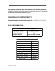
INSTALLATION Check Performance of Cabinet Components Each CP has three colored LEDs on the front panel that indicate whether it is functioning properly or not. When a cold start is performed, the system undergoes a series of self-tests and loads default translations. Upon initial power application, each CP tests itself. The red LED on the CP lights to indicate that the test is in progress. Once the CP passes its initial tests, the red LED goes off.
INSTALLATION Table 2-D. Circuit Pack Type LEDs if Normal LEDs if Failed Service Circuit (ZTN85 or ZTN131 [R3]) Steady Green and Flashing or Steady Amber Steady Red or Amber Off CPU/Memory (ZTN129 or ZTN130 [R3]) Flashing Green Steady Green or Off All Other Steady Green (Amber Also lighted when CP in use) Steady Red (see Note below) Note: 2-40 Circuit Pack LED Status Indications The red and green LEDs can both be lighted at the same time.
INSTALLATION If all the CPs are operating properly, only the green LED on the CPU/Memory CP and the amber LED on the Service Circuit should be flashing. If any other CP has a no-lighted LED, the CP may need to be reseated. All port CPs green LED remains dark until at least one port on the CP has been translated. Except for the CPU/Memory CP and Service Circuit CPs, power can be left on while a CP is reseated. To reseat a CP, do the following: 1. See CAUTION. Make sure your hands are clean and dry.
INSTALLATION Figure 2-15. Typical System 25 Port Circuit Pack Report Problems Follow local procedures to report faulty or damaged equipment.
INSTALLATION Initialize System Instructions for initializing the system (based on the completed implementation forms) are provided in the Administration Manual (555-540-500). Note: Before trunks using DS1 Signaling are administered, all link level parameters such as signaling and framing and all link level alarms must be cleared. If this is not possible, PBXs at each end will not work. If this condition exists, clear a maintenance busy condition that exists at each end.
INSTALLATION Install TAE, 617A Panels, and Fanning Strips To install this equipment, proceed as follows: 1. For each RJ21X, RJ2GX, and RJ48X network interface, install one 700A Jack 1/2-inch from the edge of the backboard closest to the switch cabinet(s). 2. Mount the first 617A Panel. 3. Position and mount the first 50A Fanning Strip next to the 617A Panel. The edges should overlap so that the same screws will go through the overlapping key slots in the 50A Fanning Strip and the 617A Panel.
INSTALLATION F I R S T 1 0 8 E T U P L Y W O O D BACKBOARD 1/2" ADD'L 700A BLOCK ADD'L 700A BLOCK ADD'L E T U ADD'L 700A BLOCK ADD'L 700A BLOCK ADD'L ETU 700A BLOCK ADD'L 617A PANEL ADD'L 617A PANEL ADD'L 617A PANEL ADD'L ETU 7 0 0 A BLOCK TO SWITCH CABINET ADD'L 6 1 7 A PANEL D-RINGS AS REQ'D FLOOR FIRST 50A FANNING STRIP Figure 2-16.
INSTALLATION NOTE: GREATER THAN 48" FOR 5-PANEL ARRANGEMENT FIRST 108 ETU Figure 2-17.
INSTALLATION Mount 858A or 2210A2 Adapters To install these adapters, proceed as follows: 1. Using a wide blade screwdriver, pry off the upper adapter mounting clip on the 617A Panel (Figure 2-18). 2. Fit the mounting clip on the top of the adapter. 3. Fit the adapter in the slot of the lower mounting clip. 4. Press the upper mounting clip back into the panel.
INSTALLATION UPPER ADAPTER MOUNTING CLIP Figure 2-18.
INSTALLATION INSTALL MODULAR BULK POWER SUPPLY (Optimal) The 346 Modular Bulk Power Supply (MBPS) is a cost-effective and flexible alternative to the KS-2291 1 power supply. The 346 MBPS can be used where the wall-mounted (outlet) KS-2291 1 power supply cannot be used or where multiple KS-2291 1 power supplies are required. The 346 MBPS consists of the 346A Power Unit and 346A1 Power Panel. Up to three 346A Power Units can be mounted in a power panel.
INSTALLATION Tie trunks must be segregated on a separate block because a different splitter cable is used. Also, off-premises stations must be segregated one 700A Jack. The first five trunks in each group of eight (loop start or ground start trunks only) can be connected through an ETU to five power failure transfer stations. However, all eight trunks are connected to, and pass through, the ETU. The ETU also supports a DID make-busy function to the central office’s extra pair (if required).
INSTALLATION Connect Cabinets to TAE Blocks The connections between the cabinets and the TAE blocks are made using connectorized splitter cables. Make sure that each trunk group on each connecting block is connected to the correct type of CP and protected with its approved secondary protector (as shown in Table 2-B). Central office trunks associated with emergency transfer and off-premises stations (OPSs) are not connected directly to the cabinets.
INSTALLATION Connect Tie Trunks A 2:1 connectorized splitter cable, WP90929, L3, is required to connect the 700A Jack to the cabinet for tie trunks. 1. Install secondary protectors (see Table 2-B). 2. Using the cable label sheets provided (Figure 2-7), label the back of the hood of each of the connectors (1 and 2) on the two legs of the splitter cable. Use an appropriate cabinet and slot number label (CAB 1 SLOT8, for example). 3.
INSTALLATION Install DS1 DS1 signaling allows a digital connection between the System 25 and other PBXs, Central Offices, Toll Offices, off premise stations, and data end points such as host computers. The TN767 emulates ground start, Ioopstart, tie and DID Trunks in addition to off premises stations. The ZTN131 circuit pack provides the required digital synchronization.The TN748 circuit pack will provide the Touch Tone registers.
INSTALLATION Figure 2-19. Direct Connection (Side by Side) NOTE: FOR DISTANCES OVER 50 FEET (15.2 M) USE C6E CONNECTOR CABLE(S) BETWEEN H600 307,G2 CONNECTOR CABLE AND DS1 TRUNK CIRCUIT PACK. Figure 2-20. Direction Connection (Side by Side) Connections Between 1311 and 4310 Feet For distances between 1311 and 4310 feet, CSUs equipped with Office repeaters must be used to regenerate the DS1 signal. See “Install CSU” section of this manual for the installation instructions for the CSU.
Figure 2-21. DS1 Connections—1311 to 4310 Feet DS1 Connections—4311 Feet or More For distances of more than 4311 feet, T1 line repeaters are required in addition to the CSUs. See the “Install CSU” section of this manual for installing the CSU. Figure 2-22 shows a functional diagram of this connection.
INSTALLATION Off Premises Metallic (Cable) Connections The connection between the System 25 and another DS1 interface is in most cases a T1 line with repeaters. The proper lightning protection must be provided (as shown in Table 2-B). Figure 2-23 shows a diagram of the off premise cabling. See the “install CSU” section of this manual for the installation instructions for the CSU. *DSX-1 REFERS TO A Figure 2-23.
INSTALLATION 655 FEET MAXIMUM MICROWAVE MICROWAVE INTERFACE INTERFACE LIGHT-GUIDE INTERFACE LIGHT-GUIDE INTERFACE INFRARED INFRARED INTERFACE INTERFACE 655 FEET ANY DS1 ANY DS1 INTERFACE INTERFACE MAXIMUM *DSX-1 REFERS TO A PHYSICAL CROSS-CONNECT FOR DS1 SIGNALS Figure 2-24. DS1 Connections—Non Metallic Connections Install Customer Service Unit (CSU) The CSU may either be rack mounted or mounted as a standalone unit.
INSTALLATION Connect the CSU The CSU can be powered by the line or from a locally provided -48 V dc power supply. Figure 2-25 shows the connections for connecting the CSU. The 48 V and GRD leads are optional according to how the CSU is powered. H600 307 ,02 CONNECTOR CABLE (NOTE) NOTE : FOR DISTANCES OVER 50 FEET ( 15.2 M) USE C6E CONNECTOR CABLE(S) BETWEEN H600 307,02 CONNECTOR CABLE AND DS1 TRUNK CIRCUIT PACK . Figure 2-25.
INSTALLATION Consideration should be given to installing secondary protection on each out-of-building facility connected to the TAE if any of the following conditions exist: ● ● ● The service entrance (protector block) ground is not properly installed (bonded to building ground, for example). The local telephone company does not permit access to the protector block. High-voltage surge protection is not provided. Install the CBC as follows: 1.
INSTALLATION INSTALL EQUIPMENT ROOM STATION CABLING System 25 is connected to the building (station) wiring in two stages. First, the building wiring is connected to the Station Interconnect Panel (SIP). Then, the octopus cables from the back of the cabinets are connected to the SIP. Accurate documentation during installation is essential to the performance and maintenance of System 25 and will make initialization and administration much easier to perform.
INSTALLATION .
INSTALLATION Connect Building Wiring to SIP The type of building wiring termination determines what types of adapters are used. Two types are supported: 4-pair cable (cut down) and modular jack. Any combination of adapters may be mounted on a 617A Panel. Cluster the connection on the SIP by voice terminal type: single-line, 7300H Series*, Multibutton Electronic Telephone (MET), and voice/data. Modular Plug Termination Each 4-pair modular plug supports one station (Figure 2-27).
INSTALLATION Z21OA1 ADAPTER (MODULAR TO MODULAR) PURSE LOCK CLIP ( TYPICAL) / Figure 2-27.
INSTALLATION 4-Pair Cable Terminations Each 4-pair cable supports one station (Figure 2-28). It connects to a wiring block on a 858A Adapter. 1. Run the 4-pair cable through the rings at the top of the 617A Panels. 2. Cut down the leads starting with Pin 1 of the wiring block located beside the modular jack (Figure 2-28). Wiring Block Pin No. DIW Cable Color Code 1 2 3 4 5 6 7 8 W-BL BL-W W-O O-W W-G G-W W-BR BR-W 3.
INSTALLATION ZZ1OA1 ADAPTER (MODULAR TO MODULAR) Figure 2-28.
INSTALLATION Connect Cabinets to SIP Table 2-E shows the type of terminals that can be connected to each CP type and the maximum allowable cabling distances to the system cabinets. Refer to the Voice and Data Station Records Form for the terminal types assigned to each workstation. C a u t i o n : Connecting a terminal to the wrong type of CP can damage the pack. Table 2-E.
NSTALLATION Prepare Carrier Loading Labels As you connect the port CPs in each cabinet to the SIP, list the connections on the Carrier Loading label. This label is mounted on the inside of the front cover of the cabinet. (See Figure 2-29.) Keep track of –48 volt power usage so that the power supply is not overloaded. 1. Enter, the CP type under the appropriate slot number. 2.
INSTALLATION 2-68
INSTALLATION Modify Octopus Cables if Required If flag--type cable ties are shipped loose, they must be installed on the early production octopus cables. The flag-type cable tie location depends on the type of SIP arrangement (Figures 2-16 and 2-17). Also, if the alternate SIP arrangement is used, later production octopus cables must be modified. 1. Check the octopus cables, if they have flag-type cable ties, go to Step 3. Otherwise, go to step 2. 2.
INSTALLATION FLATTEN OCTOPUS CABLE BEFORE FEEDING INTO THE 50A FANNING STRIP ION THE FLAG TIE WRAP IN FRONT TO SWITCH OF THE WIRE FORM MOD PLUG ENDS TO S I P F L A G WITH T I E W R A P OCTOPUS IDENTIFICATION T O S W I T C H DISTRIBUTION RING (D-RINGS) AS REQ’D Figure 2-30.
INSTALLATION Make SIP Connection for CPU/Memory In all cases, the CPU/Memory is connected to the SIP via an octopus cable. Since there are four ports on the CPU/Memory (port 1 for the SAT, port 2 for SMDR, port 3 for the DTU, and port 4 [reserved]), plugs 1 through 3 on the octopus cable are used to connect the peripheral equipment. (Plugs 7 and 8 connect to the ETU; plugs 4, 5, and 6 are not used.) Plugs 1, 2, 3, 7, and 8 plug into a designated adapter on the SIP. 1.
INSTALLATION FLAG-TYPE CABLE TIES STANDARD CABLE I MODIFIED CABLE FOR ALTERNATE SIP ARRANGEMENT (FLAG TIE AT 65” REMOVED) Figure 2-31.
INSTALLATION Make SIP Connections to Cabinet for 7300H Series Terminals 1. Select the cable label sheet (Figure 2-7) that identifies the cabinet (blue for #1, orange for #2, and green for #3). 2. On an octopus cable, attach an appropriate label (CAB1 SLOT8, for example) on the last flag-type cable tie and on the back of the hood of the 25-pair connector. 3. Connect the 25-pair connector end of the octopus cable to an appropriate receptacle (ZTN79) on the switch cabinet. 4.
INSTALLATION Make SIP Connections to Cabinet for MET Sets Follow the same procedure as for 7300H Series terminals to connect MET set SIP appearances to the appropriate CPs as outlined below: ● Connect the 25-pair connector to a TN735 CP ● Attach a cable label to the octopus cable 25-pair connector and flagtype tie wrap ● Run the cable 10 the 50A Fanning Strip ● Plug cable ends into the appropriate SIP adapters ● Complete the Voice and Data Station Records Form.
INSTALLATION ● Attach cable labels to the two octopus cable 25-pair connectors and flag-type tie wrap. ● Attach octopus cables to the 853B adapter ● Run the cables to the 50A Fanning Strip. ● Plug the cable ends into the appropriate adapters, and complete the Voice and Data Station Records Form.
INSTALLATION Make SIP Connections for Data Terminals and Computers Any RS-232C compatible data terminal, personal computer host computer, or a STAR LAN NETWORK workstation can be connected in one of four ways: ● ● ● ● If the terminal has a modem, it should be connected to a ZTN78 CP in the same way as a single-line voice terminal. The terminal’s RS-232C port may be connected to an Asynchronous Data Unit (ADU) and then to the SIP over standard building wiring.
INSTALLATION 4. Complete the Voice and Data Station Records Form (Figure 2-26).
INSTALLATION 6. Check that all cables are labeled. INSTALL EMERGENCY TRANSFER UNITS (ETUs) The 106 Emergency Transfer Unit (ETU) (Figure 2-32) supports up to five Power Failure Transfer (PFT) sets and a DID make-busy function. Up to four ETUs can be supported for a maximum of 20 PFT sets. The sets can be connected to selected loop-start or ground start trunks. PFT sets must be FCC registered single-line sets. If ground start trunks are used, a ground start button must be provided at each PFT set.
INSTALLATION Figure 2-32.
INSTALLATION Figure 2-33.
INSTALLATION Make Emergency Transfer Connections Note: The following procedure assumes that the network interfaces are connected to the 700A jacks and connector 0 of the 3:1 splitter cables has been connected to the jack. See Install Equipment Room Trunk Cabling in this part. Connect Trunk Lines From Cabinet to ETU 1. Using the cable label sheets provided (Figure 2-7), label both ends of a B25A cable.
INSTALLATION 8. Connect a 25-pair plug on octopus cable to the SIP receptacle on the ETU. 9. Mount the octopus cable on the 50A Fanning Strip (Figure 2-31). 10. Connect all eight legs of the octopus cable to adapters (port side) at the SIP. The first five stations (legs 1 through 5) are the Power Failure Transfer stations. 11. Document the connections on the Voice and Data Station Record Form (Figure 2-26). Connect ETUs (Optional) 12.
INSTALLATION Install Ground-Start Key If trunks are ground start (ZTN76 used), a ground-start key must be installed on the Power Failure Transfer voice terminals. This key can only be installed on voice terminals that have modular jacks. 1. Unplug modular line cord from voice terminal. 2.Plug KS23566, L1 key into voice terminal line cord jack. 3. Plug line cord into KS23566, L1 key. KS23566 , L1 KEY Figure 2-34.
INSTALLATION INSTALL ATTENDANT CONSOLE Most systems will have one or two attendant consoles. Release 2 Version 1 and Release 3 systems support direct trunk attendant consoles (DTAC) or switched loop attendant consoles (SLAC). The system can support either one or two of the DTAC or SLAC consoles but not a combination of DTACs and SLACs. The installation procedures for the DTAC and SLAC are the same.
INSTALLATION Figure 2-35.
INSTALLATION 4. lf a DXS is supplied, place it beside the attendant console. For locally powered DXS, do Steps 5 through 8. For remotely powered DXS, do Steps 9 through 13. Locally Powered DXS 5. Plug the 400B2 Adapter into the wall jack. 6. Plug one end of the D6AP-87 Cord into the 6-conductor modular jack of the 400B2 Adapter; plug the other end into the KS-22911, L1 power supply. 7.
INSTALLATION LEGEND : ZTN79 B1 cl C2 C7 P2 HYBRID LINE CP TYPICAL - 103A CONNECTING BLOCK MODULAR CORD (D8W-87) OCTOPUS CABLE (WP90780) MODULAR CORD (D6AP-87) NODULAR BULK POWER SUPPLY POWER UNIT (346A) POWER PANEL (346A-1) S1 - 23A1 SELECTOR CONSOLE-USED IN CONJUNCTION WITH EITHER SLAC OR DTAC W1 - INSIDE WIRING CABLE - Figure 2-36.
INSTALLATION INSTALL TERMINALS When installing terminals at workstations, consult the Voice and Data Station Records Form to make sure that you are connecting the right terminal type at each workstation. In a replacement installation, single-line and MET voice terminals already in place may not need to be replaced, although the MET labels change. Installation is required only for new terminals ordered.
INSTALLATION Label Terminals Be sure to label the feature buttons of 7300H Series voice terminals and replace labels on MET sets per Table 2-F. Table 2-F. Feature Button Abbreviations and Labels Feature Name 2-88 Administration Button Code Button Label [ ]* Account Code Entry 15 ACCT ENTRY Agent Status for CMS 42 MONITOR [PDC]* Agent Status for CMS 42 AVAILABLE Agent Status for CMS 42 .
INSTALLATION Table 2-F. Feature Button Abbreviations and Labels (Contd.) * [ ] Indicates that a meaningful value for this item should be substituted. † These features cannot be changed or reassigned. Att.
INSTALLATION Stand-Alone Voice Terminals See Figure 2-37. 1. Unpack each terminal and examine it for damage. On Model 420 voice terminals, set the TONE/PULSE switch to TONE. 2. At the workstation, connect one end of the terminal line cord to the terminal and the other end to the modular wall jack.
INSTALLATION Stand-Alone Remotely Powered Voice Terminals See Figure 2-38. 1. Unpack each terminal and examine it for damage. 2. At the workstation, connect one end of the terminal line cord to the terminal and the other end to the modular wall jack.
INSTALLATION Single-Line and 7300H Series Voice Terminals With Associated ADUs See Figures 2-39 and 2-40. 1. Unpack each voice terminal and ADU and examine them for damage. 2. Arrange 7300H Series terminals and single-line terminals with appropriate ADUs (see Note). Note: The Z3A1 ADU is equipped with a male RS-232C connector, and the Z3A4 ADU is equipped with a female RS-232C connector. The choice depends on the data terminal since both ADUs are used with single-line voice terminals. 3.
INSTALLATION B1 Cl C2 C5 WI WP90851-L1 Z3A1 ADU - TYPICAL - 103A CONNECTING BLOCK MODULAR CORD (D8W-8T) OCTOPUS CABLE (WP90780) MODULAR CORD (D4BU-87) - FURNISHED WITH SET “ INSIDE WIRING CABLE MODULAR Y ADAPTER EQUIPPED WITH A 3 FOOT PLUG-ENDED EIA CORD NOTES : 1. IF RANGE IS GREATER THAN 2000 FT FROM SYSTEM CABINET, TERMINAL DATA RATE (SPEED) MAY BE LIMITED 2. IF RANGE IS LESS THAN 2000 FEET FROM SYSTEM CABINET, USE ZTN78.
LEGEND: ZTN79 - HYBRID LINE CP TN726 - D A T A L I N E C P WP90851-L1 - MODULAR Y ADAPTER B1 C1 C2 P1 W1 Z3A5 ADU - TYPICAL -103A CONNECTING BLOCK MODULAR CORD (D8W-87) OCTOPUS CABLE (WP90780) KS22911 POWER SUPPLY INSIDE WIRING CABLE EQUIPPED WITH A 3 FOOT PLUG-ENDED EIA CORD Figure 2-40. 7300H SERIES VOICE TERMINAL 7300HSeriesTerminal/ADU Connections ATL Cordless Telephone Before placing the base at the designated location, the following things must reconsidered.
INSTALLATION Off-Premises Stations (TN742, TN746B in R3V2) An FCC-registered single-line terminal may be installed as an Off-Premises Station (OPS). Note: Only the local telephone interconnections for the OPS. company can install the The connections between the network interface and the 700A Jacks are described under “Connect Network Interfaces to TAE Jacks.” (Only the TN742 CP supports this feature.) 1. Trace the OPS pairs through the network interface to their termination on the TAE. 2.
INSTALLATION 4. Connect the cable to a protection device at the System 25 location. 5. Connect the second protection device to an 858A Adapter on the617A Panel, using 4-pair inside wiring cable. 6. Connect the 858A Adapter to a port on a TN742 circuit pack using an octopus cable. Out-of-Building Voice Terminals (ZTN79) Transmission facilities (voice pairs) that extend out-of-building and are not included in the interface may be installed by the telephone company or through other means (e.g.
INSTALLATION H600 307 .G2 CONNECTOR CABLE (NOTE) TO D4 CHANNEL B A N K NOTE; FOR DISTANCES OVER 50 FEET (15.2 M) USE C6E CONNECTOR CABLE(S) BETWEEN H600 307 .G2 CONNECTOR CABLE AND DS1 TRUNK CIRCUIT Figure 2-41. PACK.
INSTALLATION Stand-Alone Data Terminals Data terminals and computers may be connected to the system through ADUs or a Multiple Asynchronous Data Unit (MADU) without being linked to a voice terminal. Depending on the data terminal that they connect to, some ADUs may need supplementary power for proper operation. See Figures 2-42 and 2-43. ADU Connections 1. Unpack the ADU and examine for damage. 2. At the workstation, connect the ADU connector to the RS-232C receptacle of the terminal or computer.
INSTALLATION LEGEND : B1 - TYPICAL - 103A CONNECTING BLOCK C1 –MODULAR CORD (D8W-87) C7–MODULAR POWER CORD (D6AP-87) W 1 -4-PAIR INSIDE BUILDING WIRING CABLE 248B ADAPTER-ALLOWS MODULAR JACK CONNECTION FROM 2012D TRANSFORMER 400B2 ADAPTER-POWER ADAPTER 2012D TRANSFORMER - 15-18V AC TRANSFORMER Z3A1 ADU -EQUIPPED WITH A 3 FOOT PLUG-ENDED EIA CORD Z3A4 ADU -EQUIPPED WITH A 3 FOOT RECEPTACLE-ENDED EIA CORD . Figure 2-42.
INSTALLATION LEGEND : TN726 -DATA LINE CP B1 - TYPICAL - 103A CONNECTING BLOCK Cl -MODULAR CORD (D8W-87) C7-MODULAR CORD (D6AP-87) P2-MODULAR BULK POWER SUPPLY POWER UNIT (346A) POWER PANEL (346A-1) W1 -4-PAIR INSIDE WIRING CABLE Z3A1 ADU -EQUIPPED WITH A 3 FOOT PLUG-ENDED EIA CORD Z3A4 ADU -EQUIPPED WITH A 3 FOOT RECEPTACLE-ENDED EIA CORD Figure 2-43.
INSTALLATION MADU Connections The MADU provides a direct connection to a host computer or a large group of data terminals (64 maximum). See Figure 2-44. The MADU has eight port connectors; each port is equivalent to a single ADU. Complete installation instructions for the MADU are contained in the MADU Product Guide (999700-525).
INSTALLATION INSTALL CUSTOMER’S SAT The SAT can be connected through the SIP to the CPU/Memory CP by any one of the following methods: l On-premises nonswitched connection (no ADU required if the SAT is plugged into the system AC outlet) l On-premises switched connection l Off-premises nonswitched connection l Off-premises switched connection. SMDR equipment can also be connected by any of the four methods listed above. The DTU can be connected only by the on-premises nonswitched connection.
INSTALLATION LEGEND : ZTN129-CPU/MEMORY CP C1 -MODULAR CORD (D8W-87) C2 -OCTOPUS CABLE (WP90780) 355A ADAPTER -RS-232 PLUG TO MODULAR JACK 355AF ADAPTER -RS-232 RECEPTACLE TO MODULAR JACK * PERIPHERAL EQUIPMENT ● SYSTEM ADMINISTRATION TERMINAL (LEG 1 OF OCTOPUS CABLE) ● DIGITAL TAPE UNIT (LEG 3 OF OCTOPUS CABLE) ● SMDR OUTPUT DEVICE (LEG 2 OF OCTOPUS CABLE) Figure 2-45.
Nonswitched Connection of Equipment See Figure 2-46. Note: Figure 2-46 shows an Z210A1 SIP Adapter to provide the building wiring termination. An 858A Adapter can also be used. 1. Connect the RS-232C plug on the peripheral equipment to the RS232C port on a Z3A1 or Z3A4 ADU. Always tighten the screws or other fasteners on this connection. 2. Connect the ADU to the building wiring with a D8W-87 modular telephone cord. 3. At the SIP, connect the building wiring termination to an Z210A1 Adapter. 4.
INSTALLATION LEGEND : B1 –TYPICAL - 103A CONNECTING BLOCK C1 -MODULAR CORD (D8W-87) C2 -OCTOPUS CABLE (WP90780) C3-EIA CROSSOVER CABLE (P17U-87) C4 -MODULAR RECEPTACLE TO MODULAR PLUG ADU CROSSOVER (D8AM-87) C7-MODULAR POWER CORD (D6AP-87) W1 -INSIDE BUILDING WIRING CABLE 248B ADAPTER-ALLOWS MODULAR JACK CONNECTION FROM 2012D TRANSFORMER 355AF ADAPTER RS-232 RECEPTACLE TO MODULAR JACK 2012D TRANSFORMER - 15-18V AC TRANSFORMER Z3A1 ADU -EQUIPPED WITH A 3-FOOT PLUG-ENDED EIA CORD Z3A4 ADU -EQUIPPED WITH A 3-
INSTALLATION On-Premises Digital Switched Connection To access a CPU/Memory port through a switched connection, the port is connected to a port on a TN726 CP and assigned a Data Dial Code (DDC). See Figure 2-47. The peripheral equipment can be either stand-alone or associated with a voice terminal. The peripheral equipment is connected to another port on a TN726 CP. To access the CPU/Memory port, the peripheral equipment must dial the DDC of the CPU/Memory port.
INSTALLATION 11. Connect the other end of the modular cord to a 355AF Adapter. 12. Connect an M7U-87 Cord to the 355AF Adapter. 13. Connect the other end of the M7U-87 Cord to the RS-232C jack on a Z3A4 ADU. 14. Connect the ADU to a 400B2 Adapter with a D8W-87 cord. 15. Connect the 400B2 Adapter to a 2012D Supplementary Power Unit as shown in Figure 2-47. 16. Plug the 400B2 Adapter into a 2210A2 Adapter on the SIP. 17.
INSTALLATION LEGEND: B1 - TYPICAL 1- 03A CONNECTING BLOCK cl - MODULAR CORD (D8U-87) C2 - OCTOPUS CABLE (UP80780) C3 - EIA CROSSOVER CABLE (M7U-87) C7 - MODULAR POUER CORD (D8AP-87) W1- INSIDE 8UILDING WIRING CABLE 2488 ADAPTER - ALLOW MODULAR JACK CONNECTION FROM 20120 TRANSFORMER 355AF - ADAPTER (RS-232 RECEPTACLE TO MODULAR JACK) 40082 ADAPTER - POWER ADAPTER 2012D TRANSFORMER -15-18V AC TRANSFER Z3A1 ADU- EQUIPPED WITH A 3-FOOT PLUG-ENDED EIA CORD Z3A4 ADU - EQUIPPED WITH A 3-FOOT RECEPTACLE-ENDED EIA
INSTALLATION Off-Premises Nonswitched Connection Off-premises peripheral equipment must be equipped with an originating modem (see Figure 2-48). The connection is made from the CO through the TAE to a dedicated modem (optioned for autoanswer) connected to the appropriate Call Processor port. 1. Following the instructions for connecting off-premises stations, connect the OPS line from the RJ21X network interface through the TAE connecting block to the SIP. 2.
INSTALLATION SYSTEM 25 C A B I N E T PART OF OCTOPUS C A B L E ZTN128 OR ZTN130 CO OR PROVATE LINE CIRCUIT CONNECT PART OF VIA S I P TAE TYPICAL Z210A2 ADAPT.
INSTALLATION INSTALL CUSTOMER’S DTU The DTU must be directly connected to Port #3 on the CPU/Memory CP (Figures 2-45 and 2-46). Remote and switched connections are not supported. Follow the procedures provided for installing the SAT. INSTALL STATION MESSAGE DIGITAL RECORDING (SMDR) EQUIPMENT The SMDR equipment connects to Port #2 on the CPU/Memory CP. The connections are the same as those for the SAT (Figures 2-45 through 2-48). Follow the procedures provided for installing the SAT.
INSTALLATION INSTALL STARLAN NETWORK INTERFACE Note: Support for the STARLAN Interface has been discontinued. The ZTN84 STARLAN Interface CP provides an interface between the System 25 TDM bus and a STARLAN NETWORK local area network (LAN). An octopus cable connects the ZTN84 CP to a Network Extension Unit (NEU) on the STARLAN NETWORK (Figure 2-49). 1. Select the cable label sheet (Figure 2-7) that identifies the cabinet (blue for #l, orange for #2, and green for #3). 2.
INSTALLATION Shared System 25 Voice/STARLAN NETWORK Data Connections STARLAN NETWORK workstations can share the 4-pair System 25 wiring to the SIP with an analog or 7300H Series voice terminal. The STARLAN NETWORK data is transmitted over pairs two and three. At the SIP, the data pairs and voice pair(s) are separated by the standard Y-adapter (WP90851 ,L1 ). The data pairs are connected to the STAR LAN NETWORK NEU.
INSTALLATION STARLAN NETWORK NEU PART SYSTEM 25 CABINET OF Y ADAPT ZTN78 O R TN742 PART OF OCTOPUS C A B L E SIP S I P (WP90851- ADAPT L 1 ) (TYP) PERSONAL COMPUTER STARLAN NETWORK WORKSTATION LEGEND : ZTN78 TN742 699Y B1 C1 C2 C5 W1 MP90851-L1 - TIP RING LINE CP ANALOG LINE CP ATL ADAPTER TYPICAL- 103A CONNECTING BLOCK MODULAR CORD (D8W-87) OCTOPUS CABLE (WP90780) MODULAR CORD (D4BU-87) - FURNISHED WITH SET INSIDE WIRING CABLE MODULAR Y ADAPTER NOTES : 1.
INSTALLATION 73001H Series Voice Terminals See Figure 2-51. 1. Unpack each terminal and examine it for damage. 2. At the workstation, use a D8W-87 modular cord to connect the NAU jack on the KS-23475, L1 Adapter to the OUT jack on the NAU. 3. Using a D8W-87 modular cord, connect the PHONE jack on the KS- , 23475, L1 Adapter to the voice terminal. 4. Connect the POWER plug on the KS-23475, L1 Adapter to the KS22911 Power Unit. 5.
INSTALLATION LEGEND: HYBRID LINE CP MODULAR Y ADAPTER KS-23475 ADAPTER TYPICAL - 103A CONNECTING MODULAR CORD (D8W-87) OCTOPUS CABLE (WP90780) MODULAR CORDS BUILT INTO KS-23475 ADAPTER P1- KS-22911 POWER SUPPLY W1 - INSIDE WIRING CABLE ZTN79 WP90851-L1 A2 B1 C1 C2 C3 AND C4 - Figure 2-51.
INSTALLATION INSTALL MUSIC-ON-HOLD INTERFACE Note: Use of equipment that rebroadcasts copyrighted music or other material may be required to obtain a license from a third party such as ASCAP or BMI. FCC-Registered Music Source Interface The music source is connected to a ZTN78 CP through the SIP (see Figure 2-52). 1. Using an octopus cable, connect the CP to an 858A Adapter at the SIP. 2.
INSTALLATION LEGEND TN742 – ZTN78 – B1 C2 C5 W1 – MOH - : ANALOG LINE CP TIP RING CP TYPICAL - 103A CONNECTING BLOCK OCTOPUS CABLE (WP90780) PEC 2720-05P MODULAR CORD (D4BU-87) INSIDE WIRING CABLE KS-23395 INTERFACE Figure 2-52.
INSTALLATION Non-FCC Registered Music Source Interface The music source is connected to a ZTN78 CP (see Figure 2-53). Connect the CP to a 858A Adapter at the SIP. Follow the instructions for installing FCC-registered equipment. You must also install a kit-of-parts (D-181575; includes 36A Voice Coupler, 201213 transformer, and KS-23395 MOH interface). Follow the wiring instructions included with the kit.
INSTALLATION Music Source (Customer supplied) G R MSHI MSLO ❑ ❑ ❑ Music-on-Hold interface (KS-23395) (Optional) GR 909A/B Univversal Coupler (Replaces 36A Voice Coupler) DW8A-SE GR MSHI CT MSLO CR PR R PT T CT J2 Twisted Pair 26AWG Min. CR J1 T System 25 DW8A-SE ZTN78 Circuit Pack 858A Adapter J 3 -48V GRD -48dc Power Source WP-90780 Octopus Cable Figure 2-53a.
INSTALLATION This page intentionally left blank.
INSTALLATION INSTALL EXTERNAL ALERTS External alerts are connected to the system through a ZTN78 CP (Figure 254). 1. Connect the CP to a 858A Adapter at the SIP. 2. Connect the other side of the adapter to a 103A Connecting Block using building wiring. 3. Connect the block and alerting device with a D4BU cord.
INSTALLATION INSTALL RECORDED DELAY ANNOUNCEMENT Delay announcements are installed the same way as external alerts. INSTALL DICTATION SYSTEM INTERFACE If the equipment does not require a contact closure, follow the instructions for installing external alerts. If the equipment requires a contact closure, follow the instructions below for connecting a paging system to the TN763 CP. INSTALL PAGING SYSTEM INTERFACE PagePac* Paging System, or compatible paging equipment, may be connected to System 25.
INSTALLATION Direct Connection to TN763 Auxiliary Trunk CP Paging equipment can be connected directly to a TN763 Auxiliary Trunk CP ( F i g u r e 2-55) when the following conditions exist: ● ● Paging equipment is FCC registered. Paging equipment requires a contact closure for proper operation. Connect as shown in Figure 2-55, following the steps below: 1. Connect the CP to a 66-type block, using an A25D 25-pair cable. Use kit-of-parts D-1 81524 (PEC 62511).
INSTALLATION SYSTEM P A R T 25 CABINET 25 PAIR P A R T O F CABLE O F 66-BLOCK A T N 7 6 3 PAGING W 1 B1 < C 5 OR DICTATION S Y S T E M LEGEND : TN763– AUXILIARY TRUNK CP A – SINGLE-ENDED 25 PAIR CONNECTOR CABLE (A25D) B1 - T Y P I C A L -103A CONNECTING BLOCK C5 -MODULAR CORD (D4BU-87) W1 - INSIDE WIRING CABLE (4-PAIR) NOTE : APPARATUS CODE D-181523 INCLUDES 66E3-25 BLOCK CONNECTOR AND CABLE B25A 15/DE. Figure 2-55.
INSTALLATION Connection to TN763 Auxiliary Trunk CP (278A Adapter Required) A 278A Adapter is required to connect paging equipment to a TN763 Auxiliary Trunk CP (Figure 2-56) when the following conditions exist: l Paging equipment is not FCC registered. l Paging equipment requires a contact closure for proper operation. Connect as shown in Figure 2-56, following the steps below: 1. Connect the CP to a 66-type block, using an A25D 25-pair cable. Use kit-of-parts D-1 81524 (PEC 6251 1).
INSTALLATION Loudspeaker System Red Green Cross Connect F i e l d 103A o r Wall Jack B25A o r A25D Line Cord Auxiliary Cabinet or Wall Field T T R 25-Pair F Conn. on ED1E4431 0 Panel 909A/B Universal Coupler CMS2/M2 CMS1/M1 Music Source PG1/BZ1 BSY1/BY1 BSY2/BY2 PG2/BZ2 -48 V DC Power Supply 25-Pair F Conn. on ED1E44310 Panel PWR GRD +/-9.5-60V dc Power Supply Port Cabinet * Replaces: 36A Voice Coupler 89A Control Unit 27BA Adapter TN763 Circuit P a c k Figure 2-55a.
INSTALLATION This page intentionally left blank.
INSTALLATION 5. Set switch to NORMAL position. 6. Using a D4BY (single-ended) modular cord, connect D-181321 kit of parts (Figure 2-56) to a KS-22911, L2 power supply (-48V dc). 7. Connect terminals -V and GRD on 278A adapter to D-kit. 8. If background music is desired, connect terminals Ml and M2 on the 278A Adapter to the customer-provided music source. 9. Connect the 278A adapter to a 103A connecting block, using 4-pair inside wiring cable. Make the following connections: 278A Term. 103A Term.
INSTALLATION LEGEND : TN763 - AUXILIARY TRUNK CP A - SINGLE-ENDED 25 PAIR CONNECTOR CABLE (A25D) B1 - TYPICAL - 103A CONNECTING BLOCK C5 - MODULAR CORD (D4BU-87) C6 - SINGLE-ENDED MODULAR CORD P1 - KS-22911, L2, POWER SUPPLY, -48 VOLT DC W1 - INSIDE WIRING CABLE (4-PAIR) 278A ADAPTER -REQUIRES –24 VOLT ZENER DIODE KIT OF PARTS NOTES : 1. APPARATUS CODE D-181523 INCLUDES 66E3-25 BLOCK CONNECTOR AND CABLE B25A 15/DE. 2. APPARATUS CODE D-181524 INCLUDES C6, P1, 278A ADAPTER AND ZENER KIT. Figure 2-56.
Figure 2-57.
INSTALLATION Connection to ZTN76 or ZTN77 CP PagePac 20 system with ZoneMate 9/39 and Common Control Unit (CCU) provides up to nine/thirty-nine paging zones and multizone groups. To connect a PagePac 20 system, make connections using the following steps (Figure 2-58): 1. Place the PagePac amplifier on the ZoneMate and the CCU. 2. Connect the three units as follows: a. Plug the cord attached to the CCU into the modular jack on the PagePac system. b.
INSTALLATION LEGEND : ZTN76 ZTN77 A B1 C5 W1 - GROUND START C’ LOOP START C’ 3 TO 1 SPLITTER CABLE (WP-90929,L1) TYPICAL- 103A CONNECTING BLOCK MODULAR CORD (D4BU-87) INSIDE WIRING CABLE (4-PAIR) Figure 2-58.
INSTALLATION Customer-provided paging equipment can also be connected to ZTN76 or ZTlN77 CO trunk CPs. Connection to the system is made through the TAE appearance of the Tip/Ring pair of the CO trunk CP (See Appendix A for connection details). A paging equipment interface kit D-181900 consisting of a Universal Telephone Access Module (UPAM) and a -48 VDC power supply, PRS-48, is required unless all of the following conditions exist: ● ● ● Paging equipment is FCC registered.
INSTALLATION LEGEND : ZTN76- GROUND START CP ZTN77 - LOOP START CP A - 3 TO 1 SPLITTER CABLE (WP-90929,L1) UPAM - UNIVERSAL TELEPHONE (PAGING) ACCESS MODULE P 1 - PRS-48 POWER SUPPLY W1 - INSIDE WIRING CABLE (4-PAIR) NOTES : 1. APPARATUS CODE D-181523 INCLUDES 66E3-25 BLOCK CONNECTOR AND CABLE B25A 15/DE. 2. APPARATUS CODE 0-181900 INCLUDES UPAM AND PRS-48 POWER SUPPLY.
SYSTEM TESTS SYSTEM TESTS Once installation is completed, the system must be initialized, following the procedures in the AT&T System 25 Administration Manual (555-540-500). When this has been done, the system is ready for acceptance testing. You should test all trunks, voice terminals, data terminals, and features. If any equipment does not perform properly, refer to the maintenance section of this manual for more details. TEST OUTGOING TRUNKS You can test all outgoing trunks by using the *2 access code.
SYSTEM TESTS TEST INCOMING DID TRUNKS You can test DID trunks by establishing a connection on each DID trunk and then busying it out so that all DID trunks can be tested. 1. At a working voice terminal, go off-hook, dial the CO trunk access code, and then dial a DID number. You should hear ringback at the calling terminal and ringing at the called terminal. 2. At the called terminal, go off-hook and verify transmission. 3. At both terminals, lay the handsets down so that the call remains active.
SYSTEM TESTS 4. Repeat Steps 1 through 3 for all incoming tie trunks, and make sure each tie trunk is tested. TEST 7300H SERIES VOICE TERMINALS Test each 7300H Series terminal using the terminal’s test switch, by placing both station-to-station and external calls, and by using the feature buttons. 1. Push the T/P switch on the left side of the voice terminal to T, and hold it there a few seconds. If it is working properly, you should hear a steady tone. — The terminal’s red and green LEDs should flash.
SYSTEM TESTS 8. Dial the central office (CO) trunk access code. You should hear the CO dial tone. 9. Dial the listed directory number for the system you are installing. You should hear ringback at the calling terminal and ringing at the attendant console. 10. Go off-hook at the attendant position, and verify transmission. 11. At the calling terminal and attendant position, go on-hook. 12. If the station is toll restricted, place a toll call. You should hear Reorder Tone. 13.
SYSTEM TESTS TEST SINGLE-LINE VOICE TERMINALS Test each single-line voice terminal by placing station-to-station and external calls. 1. At the test terminal, go off-hook. — You should hear system dial tone. 2. Dial the PDC of another working terminal. You should hear ringback at the calling terminal and ringing at the called terminal. 3. At the called voice terminal, go off-hook and verify transmission. 4. At both voice terminals, go on-hook. 5. A t the test terminal, go off-hook.
SYSTEM TESTS TEST ATL CORDLESS TELEPHONE The ATL Cordless Telephone must be tested to see if it functions properly. The transmission quality must be verified when the base and handset are separated by the maximum operating distance. Use the documentation provided with the ATL Cordless Telephone to perform the required tests. TEST DIAL ACCESS CODES 1. Using a single-line or multiline voice terminal, verify the proper operation of each feature requiring a dial access code (Night Service access code). 2.
SYSTEM TESTS 2. At any multiline voice terminal, go off-hook, dial the ARS access code, and dial one of the long-distance numbers. Make sure that the call is completed before going on-hook. 3. Repeat Step 2 if additional long-distance numbers must be called. 4. At the SMDR printer (or SAT), verify that the call was placed over the correct trunk group. 5. If not, verify the translations through the SAT. 6. If the SAT was substituting for the SMDR printer, return the SAT to port 1.
PDC Login Test 1. At a voice terminal, go off-hook and dial * * PDC PDC, where PDC is a PDC other than that of the test terminal. — You should hear a confirmation tone. 2. At another voice terminal, go off-hook and dial the PDC that was logged into the first terminal. You should hear ringing at the first terminal. 3. At the home voice terminal of the PDC that was logged in, go offhook and dial l l PDC PDC. — You should hear a confirmation tone. 4.
SYSTEM TESTS TEST ATTENDANT CONSOLE Testing the attendant console is the same as testing a multiline voice terminal, except for testing the console’s unique feature buttons. 1. Perform all the steps in “Test 7300H Series Voice Terminal” in this section. 2. Verify that all attendant features are working properly. 3. If any features are not working or not working properly, verify the translations through SAT. .
SYSTEM TESTS TEST DATA TERMINAL DIALING FEATURE Perform this test on all data terminals and personal computers connected to the system through ADUs. 1. Make sure the test terminal is on. 2. Press . The command mode menu is displayed. (The command mode menu may be displayed before you press .) 3. Type D to select . The prompt DIAL: is displayed. 4. Enter the number of a data terminal or host you want to call and press .
SYSTEM TESTS MAKE POOLED MODEM TEST CALL Skip this test if the system does not include a TN758 Pooled Modem CP. This test involves placing a data call from a data terminal connected through an ADU from a data terminal or personal computer connected via a modem (the modem may be part of a terminal connected to System 25 or off premises). Place the call following the dialing procedure required by the modem. When you hear answer tone, transfer the call to data.
SYSTEM TESTS TEST EXTERNAL ALERT (NIGHT SERVICE) Place a test call to the attendant console to verify that the alerting device sounds when the attendant console is in the Night Service mode. If an alerting device has not yet been installed, connect a spare voice terminal or alerting device to the modular jack reserved for the alerting device. 1. At the attendant console, press the Night Service button. The Night Service LED lights steadily. 2. At any voice terminal, go off-hook.
SYSTEM TESTS TEST DICTATION SYSTEM ACCESS Place a call to verify that dictation equipment can be accessed. If dictation equipment has not been installed, this feature cannot be tested. 1. Use a working voice terminal as the test terminal, and go off-hook. 2. Dial the access code or PDC, and the number associated with the dictation equipment. 3. Verify that ready or talkdown tone is transmitted. 4. Transmission in both direction should be tested. Make a recording and play it back 5. Go on-hook.
SYSTEM TESTS TEST MUSIC-ON-HOLD Verify that music is provided to outside callers placed on hold. (Inside callers do not receive Music-on-Hold [MOH].) 1. At any working voice terminal, go off-hook. Dial the CO trunk access code and the system’s listed directory number, or if DID, dial any station. 2. At the called station, answer the incoming call. 3. At the called station, press HOLD. The line button’s green LED should flash. 4. Verify that music is heard at the calling voice terminal. 5.
SYSTEM TESTS TEST EMERGENCY TRANSFER Place the system in emergency transfer mode by turning power off (or remove the modular connector from the ETU). Place an outside call from each emergency transfer station. 1. At Cabinet 1, turn the power off using the rocker switch on the back or remove the modular connector from the ETU. 2. For ground start trunks, at an emergency transfer voice terminal, go off-hook. Press the ground start key, if so equipped. 3.
SYSTEM TESTS TEST TOUCH-TONE RECEIVERS 1. At a single-line voice terminal, go off-hook. Dial *3 and the 2-digit number (01 through 12) of the touch-tone receiver to be tested. Receivers 01 through 04 are on the ZTN85 or ZTN131 (R3) CP. Receivers 05 through 12 are only present if your system has two TN748 CPs (05 through 08 receivers on one, and 09 through 12 receivers on the other).
MAINTENANCE MAINTENANCE The primary maintenance objective is to detect, report, and clear troubles as quickly as possible with minimum disruption to normal service. Periodic system self-tests, automatic software diagnostic programs, and fault detection hardware are several of the maintenance tools used to achieve this objective. Most troubles in System 25 can be isolated to a replaceable unit. The System 25 hardware is maintained as a group of independent units (that is, maintenance objects).
MAINTENANCE EQUIPMENT NEEDED The maintenance technician should take the following tools and equipment on any System 25 service call: EIA breakout box Digital voltmeter (KS-20599 or equivalent) 11 O/66-type punchdown tool (AT 8762D or equivalent) Dracon TS21 or equivalent touch-tone test set Assorted flat-head screwdrivers Assorted Phillips-head screwdrivers Long-nosed pliers Regular pliers Wrist grounding strap Model DC4 Digital Tape Unit, with 355A adapter and a D8W cord (Comcode 404079429) Administration
MAINTENANCE Precautions Electromagnetic fields radiating from the system cabinets may generate noise in other communications equipment. The technician must be sure that all cabinet panels and covers are securely in place after performing maintenance. Caution: Electrostatic discharge can destroy or severely damage integrated circuits on CPs. The maintenance technician MUST ALWAYS WEAR A WRIST GROUNDING STRAP when handling CPs. The cord must be attached to the grounding block at the back of the cabinet.
MAINTENANCE GENERAL MAINTENANCE INFORMATION System Errors and Alarms During periodic testing, a maintenance audit could detect a system error that automatically generates an error record. Depending on severity, the error record is stored in one of following three tables in the Error Log: ● Permanent System Alarms ● Transient System Errors ● Most Recent System Errors. The three error tables can be displayed at the System Administration Terminal (SAT).
MAINTENANCE Memory (ZTN81 [RIV7] or ZTN127 [RI V2]J: The red LED on this CP lights when power is applied and goes dark upon successful completion of the ROM checksum test initiated by the Call Processor CP. Failure is indicated by a steadily lighted red LED. Call Processor [ZTN82 (R1V1) or ZTN128 (R1V2)]: The green LED on this CP lights when power is applied and flashes during normal operation.
MAINTENANCE Attendant Console LED A lighted green Alarm LED on the console indicates the presence of a Permanent System Alarm. The LED flashes with each new alarm. The attendant can press the associated button to cause the LED to light steadily. A lighted red Alarm LED indicates a barrier code violation. Power Supply LED A lighted green LED on the power supply indicates normal power operation.
MAINTENANCE Using RIMS, the remote administrator can initialize translations after the switch itself is installed. As long as there is no hardware change, the remote administrator can do ongoing administration without having to visit the customer’s site. Similarly, to trouble-shoot a problem, a technician can call the RIMS port and check the Error Log to determine the cause of the trouble. The technician can clear alarms remotely and decide whether or not a service dispatch is necessary.
MAINTENANCE Administration Requirements For a RIMS call to be made during initialization, at least one voice station and one trunk must be translated. A cold start with defaults provides these translations. The RIMS transfer code (*1 00) can be assigned to a Repertory Dialing feature button on a multiline voice terminal. If the Remote Access feature is used, the trunk used for RIMS access must be administered as a remote access trunk. Hardware Requirements Customer’s Site: None. .
MAINTENANCE MAINTENANCE STRATEGY Fault isolation is the cornerstone of the System 25 maintenance strategy. Maintenance activity isolates faults to one (or more) repairable or replaceable maintenance units. Equipment should be tested in the following order: 1. Terminal equipment 2. Station wiring 3. Port circuit packs (CPs) 4. Common control circuitry 5. Power supply and cabinet 6. Backplane.
MAINTENANCE SYSTEM TROUBLE REPORTED CAP ALARM REPORTED READ PERMANENT SYSTEM ALARMS TABLE IN ERROR L O G : AND CHECK CIRCUIT BOARDS AND POWER LED STATUS USER-REPORTED CAP ALARMED SYSTEM OR CANNOT ACCESS ERROR LOG DEFECTIVE P O W E R SUPPLY CHECK POWER LED AND FANS C P U / M E M O R Y CIRCUIT FRONTPLANE/ BACKPLANE DIAGNOSTIC TYPE OF TROUBLE INDICATED BY THE LEDS AND ERROR LOG PORTS DISCUSS THE TROUBLE WITH SYSTEM USERS POWER SUPPLY CABINET OR FANS REPLACE POWER SUPPLY READ (1) PERMANENT SYSTEM ALARM
MAINTENANCE Sometimes, faults recorded in the error log and user-reported troubles will exist at the same time. The logged faults should always be cleared first, if possible. This procedure often clears the user-reported troubles without any additional maintenance. Clearing the most serious logged fault may clear some or all of the other faults. Descriptions of the errors in the error log section indicate their relative urgency.
MAINTENANCE Common Control Problems Common Control circuitry is difficult to troubleshoot. The system must be powered down before any of these CPs are replaced. Before powering the system down, save translations to tape (see “Using the Digital Tape Unit”). Other repair procedures may also require the system to be powered down. After removing a suspected faulty CP, do the following: ● Visually inspect the CP. If a problem is identified, attach a note to the CP identifying the problem.
MAINTENANCE Station, Wiring, and Trunk Problems If the system indicates that a fault is with a station, or if a user complaint indicates a station problem, the trouble must be isolated to the station itself or to the wiring between the cabinet or station interconnect panel and the station. The station wiring, particularly the mounting cord, should be visually inspected in cases of station trouble reports. A dead station could be caused by a loose mounting cord.
MAINTENANCE USING THE DIGITAL TAPE UNIT The Model DC4 Digital Tape Unit (DTU) or equivalent is extremely important in system maintenance. System Translations are stored in the DTU and can be accessed in the unlikely event that translations are lost during a system failure. This section covers the following: ● Setting Up the DTU ● Saving Translations ● Verifying Translations ● Restoring Translations. Setting Up the DTU The DTU must be properly connected to the system before it can be used.
MAINTENANCE 4. Press the REWIND button, and wait for the unit to fully rewind the tape. This step ensures that the tape is played from the beginning. Note: The system automatically compensates for the clear “leader” material at the beginning and end of the tape. Saving Translations Follow these steps to save translations on tape: 1. Complete the steps listed above under “Setting Up the DTU. ” 2. Press both the RECORD and PLAY buttons simultaneously. (The unit should not yet begin to run.) 3.
MAINTENANCE Press c to continue, and the tape unit is automatically started by the system. Saving translations on tape takes about 5 minutes and does not affect switch performance. When the save is complete, the unit stops automatically. If the save is successful, the SAT displays: SAVE COMPLETED SUCCESSFULLY. 9. 10. Press the REWIND button and rewind the tape fully. Verify the translations saved on the tape, following the steps in the next procedure.
MAINTENANCE 5. Enter 2. The system responds with: Save/Restore: Action=2 Data=. 6. Enter D. The system completes the word Data followed by the = sign. 7. Enter 1. The system responds with the complete line: Save/Restore: Action=2 Data=1 W25: YOU ARE ABOUT TO START A TAPE VERIFY c for continue, any other key for abort . Press c to continue, and the tape unit is automatically started by the system. Verifying translations takes about 5 minutes.
MAINTENANCE Restoring Translations Note: Restoring translations from tape removes the system from operation for about 5 minutes. When it is necessary to restore system translations from tape, follow these steps: 1. Complete the steps under “Setting up the DTU,” using the cassette on which translations were saved. 2. Press the PLAY button on the tape unit. (The unit will not run at this time.) 3. Log on to the SAT, if not already logged on.
MAINTENANCE Press c for continue, and the tape unit is automatically started by the system. Restoring translations takes about 5 minutes. When restoration is complete, the unit stops automatically. If restoration is successful, the SAT displays: (feature code issue, date, time, size) followed by: RESTORE COMPLETED SUCCESSFULLY Initiated warm start 8. If above message is not displayed on the SAT, restoration was probably not successful.
MAINTENANCE ROUTINE MAINTENANCE The following are general trouble-clearing techniques usually required to resolve system-detected and/or user-detected troubles. ● Reseating and Replacing Circuit Packs ● Removing and Restoring Power ● Restarting the System. Reseating and Replacing Circuit Packs Except for the CPU/Memory and Service CPs, power can be left on while a CP is reseated or replaced. When possible, CPs should not be removed when the amber LED is lighted.
MAINTENANCE 6. Inspect the cabinet backplane and the connectors at the back of the CP. It may be possible to clean dirty connectors per prescribed procedures and return the CP to service. However, if any connectors are damaged or corroded the CP should be replaced. 7. Rest the CP on a firm nonconducting surface, and press in all socketed devices on the CP to be sure that they are firmly connected. Ensure that all straps (if there are any) are firmly seated. To Replace or Reseat a CP: 1.
MAINTENANCE Removing and Restoring Power When the following procedures are performed, the system must be unplugged from the ac power source: ● ● Reseating or replacing the Service Circuit or CPU/Memory CPs Replacing the frontplane ribbon connector between the Call Processor and Memory CPs (Release 1 only) ● Replacing the power supply ● Replacing the fan assembly. Danger: The System 25 cabinet(s) contain hazardous voltages. This equipment must be serviced only by qualified technicians. .
MAINTENANCE Restarting the System The system automatically warm starts after power is restored. (The system’s maintenance software may restart the system under certain self-detected error conditions. ) There are two types of restart: cold and warm. A Cold Start and limited cold start (which takes about 4 to 5 minutes) causes the system to check all slots for valid CP types and assign default translations to all ports except auxiliary trunk ports. Current translations are not retained.
MAINTENANCE 6. Enter 9 (for the SAVE/RESTORE selection) and press . 7. The system responds with: Action= 8. Enter 10 for a warm restart. The system responds with: Save/Restore: Action=10 Data=. 9. Enter D. The system responds with: D a t a = 10. Enter 1. The system responds with: Save/Restore: Action=10 Data=1 YOU ARE ABOUT TO FORCE A WARM START c to continue, any other key for abort. 11. Enter c to initiate the warm restart.
MAINTENANCE Messages displayed on the SAT indicate which restart is being performed. The same type of information is displayed for a cold and a warm restart. This information consists of a listing of the version of the firmware loaded in the CPU/Memory CP and a configuration listing of all CPs recognized by the system. The CPU/Memory CP is not listed in the configuration listing; however, it should be located in slot 1 of Cabinet 1.
MAINTENANCE The SAT message for a cold restart appears after the system has performed all self-tests and reading of its configuration. The time required for a cold start depends on the number of CPs in the system but is generally several minutes. A typical Release 2 cold restart SAT message is as follows: RESTART TS ROM pair FC ROM pair FC ROM pair FC ROM pair C0LD START SLOT 1 2 3 4 5 6 7 8 9 10 11 12 ● 1: version 3.5 * 1: version 3.13 * 2: version 3.13 * 3: version 3.
MAINTENANCE ERROR LOG When a system maintenance object fails periodic testing, the system automatically generates an error record. Depending on severity, the record is stored in one of three tables in the Error Log. The Error Log contains the following three error tables: These are failures that cause degradation of service and require immediate attention. These alarms will light the Alarm LED on the Attendant Console and are stored in the Error Log Permanent System Alarm table.
MAINTENANCE A typical error record from the Permanent System Alarms and Transient System Errors table is as follows: PERMANENT SYSTEM ALARMS LAST BOARD FIRST PORT NUMBER CODE OCCURRED OCCURRED 10400 ZTN130 23/12:30 30/01:56 COUNT NAME 1 Port Board missing But Administered Interpret this record as follows: ● ● ● ● ● ● 4-28 “Port Number” 10400 is the 5-digit port identification number specifying the location of the error.
MAINTENANCE Error records in the Most Recent System Errors table have a slightly different format. A typical error record from the Most Recent System Errors table is MOST RECENT SYSTEM ERRORS TIME NAME PORT BOARD DATE OCCURRED OCCURRED NUMBER CODE 30300 ZTN131 03/12/85 2:01:56 Port Board Missing But Administered Interpret this record as follows: ● “Port Number” 30300 is the 5-digit port identification number.
MAINTENANCE The Error Log is under the control of internal background maintenance software that automatically escalates an error to a more serious category or retires it. The system tests itself after a repair has been made. If the error condition is corrected, the error may be removed from the Error Log. Although some errors are automatically retired from the Error Log, they can also be manually retired by entering commands at the SAT.
MAINTENANCE 9. 10. Enter 1 and press . The SAT displays: SEARCHES: ACTlON=1 DATA= 11. Enter D. The system completes the word Data followed by the = sign. 12. . After Data= enter one of the following numbers, depending on which error table you wish to see: ● 30 to see Permanent System Alarms ● 31 to see Transient System Errors ● 32 to see Most Recent System Errors. If you select 30, for example, the system responds with: SEARCHES: Action=1 Data= 30.
MAINTENANCE ERROR MESSAGES Error messages, along with the alarm indicators, are the most likely indicators that an error has occurred in the system. When a maintenance object fails periodic testing, the system automatically generates an error record. The error record (log) is accessible through the SAT. The following table lists and describes error messages that can be displayed on the SAT. The table also includes possible solutions for some of the errors that are encountered.
MAINTENANCE ERROR MESSAGE AND DESCRIPTION POSSIBLE SOLUTION AC Power Failure: An indication that ac power has been lost (for example, plug removed from a wall receptacle, building power down for more than a quarter of a second, etc.). If power is lost from the first cabinet, the ETU will be triggered. Check plug at wall receptacle. If this error occurs more often than the building power outages, check connection to wall.
MAINTENANCE ERROR MESSAGE AND DESCRIPTION Bad Port: (STARLAN Interface CP) This error is an isolated transient condition. Bad Ringing Supply: Problems detected with ringing portion of power supply. POSSIBLE SOLUTION Recoverable; no action required. Check ring voltage on associated power supply (see Figure 4-2). Belated External Release: S e e “No External Release on PBX Disconnect. ” Normally, no action required; however if problem persists, check for faulty trunk (see Figure 4-3).
MAINTENANCE ERROR MESSAGE AND DESCRIPTION POSSIBLE SOLUTION D C F a i l T r a n s i e n t Record: No action required; this error Indicates a dc power failure. display is a record of the start time of the failure. DC Power Failed: Indicates the absence of +5 V dc on a cabinet. Each cabinet has its own power supply; therefore, this may not cause a warm start. Check the +5 V dc voltage level on the power supply (see Figure 4-2). DC Power Restored: Indicates that +5 V dc has been restored.
MAINTENANCE ERROR MESSAGE AND DESCRIPTION POSSIBLE SOLUTION DXS Reset; The DXS console has been reset. Recoverable; no action required. Electronic P o w e r F e e d O f f , Line A Hybrid Overcurrent: (ZTN79) port EPF chip shut down. Two ports are effected, for example, 1-2,3-4,5-6,7-8. Check the wiring for shorts from the backplane/SIP up to the phone jack. Check the ATL set at the SIP. Try swapping ATL sets. Error removed if Audit passed and short removed. Audit runs every 4 minutes.
MAINTENANCE ERROR MESSAGE AND DESCRIPTION POSSIBLE SOLUTION External Stack Full: (STARLAN Interface CP) This error resets the CP. If the reset is not successful reseat board. If the reseat fails, replace the board. Outgoing Seizure: Fault on ZTN76/TN747 CO ground was not detected within a predetermined ZTN77/747 loop time-frame. current was not detected within a predetermined time frame. Check trunk for slow dial tone; more than 10 seconds.
MAINTENANCE ERROR MESSAGE AND DESCRIPTION POSSIBLE SOLUTION The Problem could be with the Illegal Instruction: This error is logged when an illegal instruction ROM on the CPU/Memory CP. If is encountered by the CPU. the problem persists, check or replace CP. Illegal Interrupt: CPU/Memory CP problem. The CP may still pass the powerup test for the ROM. Check or replace the CPU/Memory CF. Illegal Port Command: (STARLAN Interface CP) This error is an isolated transient condition.
MAINTENANCE ERROR MESSAGE AND DESCRIPTION Invalid Message Length: The port CP sent an up-link message that is not in the expected message set. POSSIBLE SOLUTION If the problem persists, check or replace the port CP. Invalid Port Board: (Other than CPU or Memory) Port CP not supported by system. Remove or replace CP with a board that is supported by System 25. Invalid Port Message: The port If problem persists, check or replace the port CP.
MAINTENANCE ERROR MESSAGE AND DESCRIPTION POSSIBLE SOLUTION error that occurs while accessing the “other than protected” RAM. A warm start is logged after this error. Possible software error. If problem persists, check or replace CPU/Memory CP. A warm start or retranslation of the system could be a possible fix for this problem. Memory ROM Checksum Error: Memory has failed the ROM test. If this problem persists, replace CPU/Memory CP.
MAINTENANCE ERROR MESSAGE AND DESCRIPTION POSSIBLE SOLUTION On-HookBeforeReady To Receive Digits: For a tie trunk with delay dial or wink start—after the handshake is complete, a 50-ms guard time must pass before digits are received. If the far-end goes on-hook before guard time elapses, this message is logged. Recoverable; no action required.
MAINTENANCE ERROR MESSAGE AND DESCRIPTION POSSIBLE SOLUTION Port CP Missing B u t “Administered: (Other than CPU/Memory) Translated port CP that CPU cannot access. Check CP slot; reseat CP; change CP; or remove C P f r o m translations. If CP does not pass power-up, replace CP. Port CP Out Of Service: (Other than CPU/Memory) Message occurs when a CP is removed from a cabinet. Error removed when the CP passes power-up.
MAINTENANCE ERROR MESSAGE AND DESCRIPTION Received Incorrect Number of DID Digits: This error indicates that the CO is set up to send a number of DID digits different from what the switch has been administered to receive. RIMS Insane: Service Circuit or Tone Detector CP problem. POSSIBLE SOLUTION Ensure that trunks are properly translated. Notify local CO to verify the correct number of digits to be sent. Test trunk per Figure 4-3.
MAINTENANCE ERROR MESSAGE AND DESCRIPTION S e r v i c e Circuit Test Failed: Service Circuit demand test failed on the DTMF receivers. POSSIBLE SOLUTION Check TDM bus terminator and cabinet interconnect cables. If the problem persists, replace ZTN85 or ZTN131 (R3). of external Signaling Lead Fault: Auxiliary C h e c k wiring equipment per Figure 4-7. Trunk CP is expecting a ground from external equipment but none is detected.
MAINTENANCE ERROR MESSAGE AND DESCRIPTION POSSIBLE SOLUTION Trunk Call Dropped: A call that had been up on a trunk for more than 9 hours has been detected by an audit and dropped. The port associated with the error identifies the trunk in question. Normally, no action required; however, if problem persists, perform trunk test call per Trunk Troubles procedure in this Part. Also, check the CO disconnect and trunk timing.
MAINTENANCE ERROR MESSAGE AND DESCRIPTION Command: Unrecognized (STARLAN Interface CP) This error is an isolated transient condition. User Forced Warm Start: System was warm started through the SAT. Warm Start: System was restarted for some reason; translations are okay. POSSIBLE SOLUTION Recoverable; no action required. Recoverable; no action required. Power supply may be out of regulation (see Figure 4-2). Check remaining errors in the alarm tables for associated problems.
MAINTENANCE . . Figure 4-2.
MAINTENANCE Figure 4-2.
MAINTENANCE Figure 4-3.
MAINTENANCE Figure 4-4.
MAINTENANCE Figure 4-4.
MAINTENANCE Figure 4-4.
MAINTENANCE Figure 4-4.
MAINTENANCE NOTES : 1. PC should be running NAUCOM, Session, CAM and/or any STARLAN NETWORK compatible emulating program. 2. The green LED lights when the STARLAN CP passes power up. Figure 4-5.
Figure 4-6.
MAINTENANCE [6] [7] [8] [9] [10] Figure 4-6.
MAINTENANCE Figure 4-6.
MAINTENANCE Figure 4-6.
MAINTENANCE Figure 4-6.
MAINTENANCE Figure 4-7.
MAINTENANCE Clearing System-Detected Troubles Most troubles are detected through the Alarm LED located on the Attendant Console, the Error Log, and, in some cases, the LEDs on the circuit packs (CPs). The following is a list of system troubles. Each item in the list is described in this section.
MAINTENANCE Failure of the CPU/Memory CP at power-up generates the following type of error message: FAIL: : : : The bracketed fields contain the following information: ● is CPU/Memory ● is one of the following: RAM TEST ROM TEST AA INTERFACE DUART TEST REAL-TIME-CLOCK TEST BUS ERROR WORK CYCLE D P R T E S T MMU TEST AA RESET STUCK : SC? ● specifies the specific location of the failure, such as the address of a failed integrated circuit.
MAINTENANCE After total failure, the system ceases to operate and the green LED on the CPU/Memory CP may not flash. Failure can also be verified by checking the LEDS on each CP. If either a partial or total Common Control failure is detected, remove and then restore system power. This procedure forces the system to perform a warm restart. If the failure exists after system restart, remove power again and reseat CP suspected of being faulty.
MAINTENANCE Once a faulty CP is identified, it can be replaced using the procedures in “Reseating and Replacing Circuit Packs” under “Routine Maintenance. ” Refer to the information in “Circuit Pack LEDs” under the “General Maintenance Information” to understand the meaning of the CP LEDs. . If the Error Log notes an error related to the touch-tone receivers, the receivers are performing below system requirements.
MAINTENANCE Table 4-B lists the test points (-5 V, +5 V, -48 V, and GND) for the power supply. The test points are located on the upper-right corner at the front of the cabinet. Table 4-C lists the voltages used by the CPs and symptoms that occur when voltages are missing. This information is useful in diagnosing power supply or power distribution problems. Table 4-B. Test Points +5 Voltage Limits Power Supply Test Points Remarks +4.80 +5.
MAINTENANCE Table 4-C. Voltage/ Circuit Pack (Notes) Call Proc.
MAINTENANCE Each power supply has one green LED on its front that can be seen through the fan assembly. The LED is visible through the ventilation slots on the front cover, but the cover must be removed for diagnostic and service purposes. This LED is always lighted when the system is receiving 5.1 volts power. The LED is dark when there is a failure in the +5 volt power supply or power connections, or when there is a short on the backplane.
MAINTENANCE AC DISTRIBUTION UNIT AC CIRD VARISTOR PWB ASSY CM 538A1 S1 SW TO 15A 120 VAC OUTLET GROUND BLOCK Figure 4-8.
MAINTENANCE Power Supply Protection Power supply outputs are protected from damage when they are subjected to either momentary or sustained short circuits. “Shutdown” current protection is provided at 125 percent (plus or minus 5 percent) of full load for each dc output. Current foldback is provided for the 90 V ac output. Output power is removed when the output voltage exceeds an internally set trip point. The trip point is set at the factory at +6.25, +0.75 V for the +5.
MAINTENANCE Power Supply Replacement To replace the power supply, follow these steps: Danger: Hazardous voltages are present on some backplane pins. Unplug power cord from the outlet, and wait at least 5 minutes before removing rear cover or power supply. 1. Remove the front cover of the cabinet. 2. Remove the four No. 6-32 screws at the corners of the fan assembly. 3. Unplug the fan assembly from system power by removing the two modular plugs on the left side of the assembly. 4.
MAINTENANCE Fan Assembly Trouble The fans should always be operating when the system is receiving ac power and the cabinet switch is turned on. If the fans are not operating, be sure that the system is receiving ac power. if the system is receiving power and the fans are still not operating, the ac power connection to the fan assembly is faulty or the fans themselves are faulty (for example, burned out motors).
MAINTENANCE Overheating Trouble A clogged or dirty air filter can cause the cabinet to overheat. The cabinet air filter rests on the floor of the cabinet under the CP carrier. The air filter should be inspected on any service call and replaced as needed (with air filter comcode 845948348). Caution: Check underneath cabinet for paper and other debris that could clog the air filter and cause the cabinet to overheat. To replace the air filter, pinch it in the center and pull straight out.
MAINTENANCE TEST POINT CABLE CONNECTS HERE. ACCESS VOLTAGE TEST POINTS FROM FRONT OF CABINET. Figure 4-9.
MAINTENANCE Figure 4-9.
MAINTENANCE Figure 4-10.
MAINTENANCE Figure 4-11.
_ MAINTENANCE Each of the 12 universal carrier slots has 48 pins on the backplane for connection to station and trunk ports. The 48 pins are divided into eight groups of 6 pins each, one group for each port circuit. Lead designations consist of the lead name suffixed by the group number (for example, TA.2, RA.2). Specific functions depend on the type of port CP. Table 4-D provides the 25-pin connector to backplane pin designations.
MAINTENANCE Table 4-D. 25-Pin-Conn. Pin No.
MAINTENANCE Table 4-D. 25-Pair Connector to Backplane Designations Contd) 25-Pin-Conn.. D I D T i e A u x . D a t a Analog A n a l o g D S 1 B a c k p l a n e Pin No. W i r e T r u n k T r u n k T r u n k L i n e L i n e L i n e I n t e r f a c e P i n N o .
MAINTENANCE 8' CABLE LENGTH CONNECTOR 1 CONNECTOR 0 CONNECTOR 2 STOCKLIST DESCRIPTION 2 5 - P R P L U G 8-FT, 8-PR, 24-GC, CABLE 25-PR RECEPTACLE SPACER (NOTE 1) NOTES: 1. INSTALL SPACER AT CONNECTOR CABLE CLAMP TO ENSURE PROPER CABLE RETENTION. 2. ITEMS 1 AND 3 SHALL BE EQUIPPED WITH SCREWS TO FACILITATE ASSEMBLY TO B25A CABLES. 3. LABEL CONNECTORS AS SHOWN: 0,1,2.
MAINTENANCE Emergency Transfer Unit Trouble If the Emergency Transfer Unit (ETU) will not enter the power failure mode, do the following steps: 1. Unplug the cable bringing the control signal from port 7 or 8 on the CPU/Memory CP to the ETU. This cable terminates in a modular jack that is inserted in a modular plug labeled CPU on the left-hand side of the ETU. 2. If the ETU goes into the power failure mode, the CPU/Memory CP is probably faulty or a wiring problem exists.
MAINTENANCE CLEARING USER-DETECTED TROUBLES User-reported troubles are usually associated with voice or data terminal equipment or trunks. They can result from system-detected errors and are often solved by clearing system error conditions or alarms. This section presents trouble-clearing techniques and procedures for userreported troubles.
MAINTENANCE N o t e : For problems with administration equipment that is not connected on a dedicated basis, refer to the Terminal Operations Manual, 555-540-710. Time-Keeping Troubles Symptoms: Clock doesn’t reflect current time or date. Procedures: 1. Reset clock from SAT (see the Administration Manual). Clock has tolerance of plus or minus 3 minutes per month. Variances outside this range indicate a faulty clock and require replacement of the CPU/Memory CP.
6. Check CP translations from the SAT to be sure that this CP has 7. Check LEDs on CP. The red LED will be lighted if a fault on the CP affects all ports. Also, the red LED may be lighted if one or a few ports are faulty. 8. Check Error Log for relevant messages. 9. Reseat the CP even if the red LED is dark. (See “Reseating and Replacing Circuit Packs” under “Routine Maintenance” in this section.) Replace the faulty CP. Voice Transmission Troubles Symptoms: Voice terminals not receiving tones.
MAINTENANCE If you hear dial tone, continue with this test. 2. Dial the digits 1234567890 *#. YOU should hear a DTMF signal as each key is pressed. If the test passes, you will hear dial tone within 1 to 3 seconds after you enter #. 3. Repeat the test for each touch-tone receiver. 4. Replace the Service Circuit CP if this test fails. 7300H Series Terminal Troubles Symptoms: 7300H Series terminal LEDs and/or tones not functioning properly. Procedures: 1.
MAINTENANCE Procedures: 1. Make sure that the appropriate ZTN79 CP is translated. 2. Check for the presence of -48 volts at test point on front of cabinet. Symptoms: Inoperative display-equipped voice terminal when LOCAL button is used. Procedures: 1. If LOCAL button/lamp activate LOCAL button. is off, and voice terminal is inoperative, 2. If terminal is still inoperative, check for other problems.
MAINTENANCE Figure 4-12.
MAINTENANCE Figure 4-12.
MAINTENANCE Figure 4-12.
MAINTENANCE Trunk Troubles Many trunk troubles originate in the central office (CO) facilities. The first step in identifying trunk troubles should be to check for presence of dial tone at the Trunk Access Equipment (TAE). If required, check the Error Log records, and make a trunk test call. Note that it is sometimes difficult for the user to detect or identify trunk troubles. If an outgoing trunk is down, an error is recorded in the error log and the trunk is taken out of service (see Note ).
MAINTENANCE 5. Listen for dial tone from the accessed trunk. If dial tone is not present, isolate the fault to a trunk port CP or location in the trunk access equipment, etc., using a test set. 6. If dial tone is present, dial a working outside number. Verify that the call is complete. 7. If trunk is busy, fast busy tone is heard. If a nonport trunk was dialed, fast busy tone is heard. Incoming Trunk Problems Symptoms: Incoming trunks (of any type) not working properly. Procedures: 1.
MAINTENANCE 6. If “no loop current on outgoing call” is displayed, either of the above conditions could be true. It is more likely, however, that the facility is down. 7. Place an outside call on the line using the trunk test call procedures listed in outgoing Trunk Problems. If you get fast busy tone, switch trunk ports and try again. 8. If the problem does not move, replace the Loop Start CP. 9. If the problem moves, the fault is with the CO. Notify CO personnel through the proper channels.
MAINTENANCE 8. If the problem does not move, replace the Ground Start CP. 9. If the problem moves, the fault is with the CO. Notify CO personnel through the proper channels. 10. If “Ringing no ground” is displayed, the T and R leads may be reversed in the trunk access wiring. The T lead should have ground, and the R lead should have –48 volts. These can be verified by reversing the ground and ring leads and checking with either a voltmeter or a test set (with a polarity switch).
MAINTENANCE ● CO failure to release after PBX disconnect ● CO belated release. These messages indicate CO problems. The first three errors are very common when DID trunks are installed. The CO should be notified through the proper channels about any of these problems. 3. The CO failure to release after PBX disconnect can frequently be corrected by disconnecting and then reconnecting the DID trunk. If this procedure does not resolve the problem, notify the CO through the proper channels. 4.
MAINTENANCE Figure 4-13.
MAINTENANCE 4-13.
MAINTENANCE Figure 4-13.
MAINTENANCE 4-13.
MAINTENANCE NOTES : 1. (a) System defaults to a DTAC when first powered up. (b) You have to remove the DTAC before you can administer the SLAC . (c) System 25 can support 1 or 2 DTAC or 1 or 2 SLAC but not a combination of both. 2. ID names can be assigned for PDCs, Trunks, FPDCs, and DGC groups.
MAINTENANCE Special Port Circuit Options for Stations and Trunks Tables 4-E and 4-F provide the special port circuit options that are administered in the system. System defaults and associated action codes applicable to the various port CPS are also shown. Procedures are available in the Administration Manual for logging onto the system and accessing the information shown in Table 4-E.
MAINTENANCE Table 4-F. Applicable Actions for Circuit Pack Options ACTIONS FOR CIRCUIT PACK OPTIONS (See Circuit Pack Options—Table 4-E) CIRCUIT CP ACTIONS TYPE 32 33 34 35 36 37 38 , PACK ZTN76 GS Board ● ● ● ● ● ● ● ● ZTN77 LS Trunk ZTN78 Tip/Ring Line ● ● ● ● ● ● TN742 Analog Line TN753 DID Trunk ● ● ● ● ● ● TN760B Tie Trunk ● ● ● ● ● TN763 Aux Trunk ● TN767 DS1 Interface ● ● ● Note: TN747 same as ZTN76 and ZTN77. TN746B same as TN742.
6. If +7 volts are not present, the ADU is not receiving enough power from the data terminal and must be locally powered. 7. If the ADU is powered from a local transformer, make sure that a 3pair or 2-pair modular cord is connected between the transformer and the ADU. 8. Using a 4-pair modular jack breakout box, check to be sure that the ac voltage between pins 7 and 8 is about 14 volts under load or about 28 volts for an open circuit. 9.
MAINTENANCE Multiple Troubles or Trouble That Cannot Be Diagnosed Symptoms: Red LED is lighted on all port CPs. SAT displays this message: “FAIL: CPU: A R C H ANGEL INSANE: CHECK ZTN85: TERMINATOR?”. Procedures: 1. Check that the TDM bus terminator card(s) is installed in the rear pin field(s). bus Note: The CPU/Memory CP provides built-in termination circuitry for one end of the bus, and the TDM bus termination card is used to terminate the other end. 2.
MAINTENANCE Symptoms: Red LED is lighted cm several port CPs. Procedures: 1. Check the power supply to be sure that it is providing correct voltages (see “Power Supply Trouble’ ‘). 2. Check the frontplane connector and the CPU/Memory CP, and replace any faulty unit(s). 3. Reseat any CPs where the red LED is still lighted. After reseating a CP, if the red LED remains lighted, replace the CP. 4. If troubles persist, check the backplane for signs of shorts or other troubles.
REFERENCES The following System 25 documents are available for reference. A brief description of each manual is provided.
REFERENCES An Introduction to AT&T System 25 Provides an introduction to System 25 features and services. The emphasis is on how System 25 helps solve information management, productivity, and cost control problems. Implementation Manual Describes how to plan the system’s operating configuration. Explains how to determine customer needs and how to convert these needs into a system configuration plan.
REFERENCES Reference Manual This document is the system’s principal technical reference. It provides reference material for sales support, system configuration and operation, and for the system technician. It contains a comprehensive description of the system, emphasizing features, components and overall capabilities and capacities.
REFERENCES Call Management System—System Manual Provides information necessary to install CMS software, administer, use, and troubleshoot CMS. Call Management System—lnstallation Guide Provides instructions for inserting the CMS interface card into the PC. Call Management System—Planning Guide Provides detailed information necessary to make decisions necessary to install and administer CMS per customer requirements.
ABBREVIATIONS AND ACRONYMS ABBREVIATIONS AND ACRONYMS ADU AE ARS ASCII Asynchronous Data Unit Account Executive Automatic Route Selection American Standard Code for Information Interchange BPS Bits Per Second CCS CCSA COS CSU Hundred Call Seconds Common Control Switching Arrangement Class of Service Customer Service Unit DCE DDC DDD DID DGC DS1 DTAC DTE DTMF DXS Data Communications Equipment Data Dial Code Direct Distance Dialing Direct Inward Dialing Direct Group Call Digital Signal Level 1 Direct
ABBREVIATIONS AND ACRONYMS LDN LED Listed Directory Number Light-Emitting Diode MET MOH Multibutton Electronic Telephone Music-on-Hold NAU NEU NPA Network Access Unit Network Extension Unit Number Plan Area OPS Off-Premises Station PDC PDS Personal Dial Code Premises Distribution System RAM RNX ROM Random Access Memory Private Network Office Code Read Only Memory SAT SIP SLAC SMDR System Administration Terminal Station Interconnect Panel Switched Loop Attendant Console Station Message Detail R
APPENDIX A: APPENDIX A: System Wiring Tables Connector Pin Assignments Table A-A lists the lead designations and pin assignments at the 25-pair connectors on the system cabinets. System 25 Building Wiring Table A-B lists the 25-pair and 4-pair cable color codes, voice and data terminal lead designations, and connecting block terminal punch-down information.
APPENDIX A: System Wiring Tables Table A-A. 25-Pin Corm. C a l l Pin No. W i r e Proc.
APPENDIX A: System Wiring Tables Table A-A. 25-Pin Conn. Pin No. ‘W i r e Color 26 1 27 2 28 3 29 4 30 5 31 6 32 7 33 8 34 9 35 10 36 11 37 12 38 13 39 14 40 15 41 16 42 17 43 18 44 19 45 20 46 21 47 22 48 23 49 24 50 25 W-BL BL-W w-o o-w W-G G-W W-BR BR-W w-s s-w R-BL BL-R R-O O-R R-G G-R R-BR BR-R R-S S-R BK-BL BL-BK BK-O O-BK BK-G G-BK BK-BR BR-BK BK-S S-BK Y-BL BL-Y Y-o o-Y Y-G G-Y Y-BR BR-Y Y-s s-Y V-BL BL-V v-o o-v V-G G-V V-BR BR-V v-s s-v 25-Pair Connector Pin Assignments (Contd) DlD Tie Aux.
APPENDIX A: System Wiring Tables Table A-B. Building Wiring 25-Pair Cable Term. Lead Functions 500 ATL 7 1 0 1 A Cordless D-Inside Cable Ckt. 2 5 0 0 7300H RS-232C Color No.
APPENDIX A: System Wiring Tables Table A-B. Ckt. No. 6 Spare Building Wiring (Contd) 25-Pair Cable Term. Lead Functions 500 ATL D-inside 7101A Cordless Cable 2500 7 3 0 0 H RS-232C C o l o r Code Term . Series Series V-BL T T BL-V R R v-o CT TXT o-v CR TXR V-G PPXT G-V P+ PXR V-BR BR-V v-s s-v 4-Pair Cable Conn. Pin Num. 46 21 47 22 48 23 49 24 50 25 D-lnside Cable Conn. Color Block code Term.
APPENDIX B: APPENDIX B: Parts Listing The following information may assist you in cross-referencing Apparatus Codes, Comcodes and Price Element Codes (PECs). DESCRlPTI0N PEC APPARATUS CODE COMCODE Cabinets includes J58901 A2 L-1 5 (e/w) System 25 Control Unit (R3V2) 6250-031 Carrier Power Supply Fans Ass’y WP90510, L2 WP90677, L2 845948348 845416635 Air Filter Address Plug TDM Bus Term.
APPENDIX B: Parts Listing DESCRIPTlON PEC APPARATUS CODE COMCODE System 25 Control Unit (R1V2) 6250-012 Carrier Power Supply Fan Assembly Air Filter Address Plug TDM Bus Term, Memory CP Processor CP Service Circuit CP SLAC Grap.
APPENDIX B: Parts Listing DESCRIPTlON PEC APPARATUS CODE COMCODE Upgrade Kit (R3V1/V2 to R3V3) 62527N * ZTN142 * GS Trunk CP 62502 ZTN76 103965232 LS Trunk CP 62503 ZTN77 103965240 TR Line CP 62504 ZTN78 103965257 ATL Line CP 62505 ZTN79 103965265 STARLAN Interface CP 62518 ZTN84 103965315 Analog Line CP 63111 TN742 103556957 MET Line CP 63112 TN735 103556882 DID Trunk CP 63116 TN753 103557062 Tie Trunk CP 63140 TN760D 106360142 Aux Trunk CP 63118 TN763D 10640561
APPENDIX B: Parts Listing DESCRIPTlON PEC APPARATUS CODE COMCODE Digital Tape Unit 62507 TS-555A 404079436 System Admin.
APPENDIX B: Parts Listing DESCRIPTION PEC APPARATUS CODE COMCODE MET Set-BIS Transformer Kit-of-Parts 3141-BIS 2993C04 2012D 13181245 103942146 102600517 * 12-button MET Set 3143-12M Z7203M01 A-003 103963310 MET Adapter Cord 2750-A17 ZD8AJ 103881421 5-Button 7300H Ser VT 3160-111 (MAC30 Att) Z7302HO1D-003 ● 10-Button 7300H Ser VT 3161-172 (MAC30 Att) Z7303H01D-003 ● 7300H Ser.
APPENDIX B: Parts Listing PEC APPARATUS CODE COMCODE Acoustic Coupler 31710 104010061 Single-Line VT w/Message Light & Recall button Ground Start Key 3170-OOM 349A Adapter 7101A01A-003 31017 55A1 100287143 100013978 DESCRIPTION 103871109 Mounting Bracket 77A Ground Start Key External Alert 31019 KS23566,L1 E1CM-50 Message Adjunct 31032 Z3A1 405792339 102917952 103966396 lROB Unit 32918 ITW343 406721738 Mod. Bulk Pwr.
APPENDIX B: Parts Listing DESCRIPTlON PEC APPARATUS CODE COMCODE ATL ADU 62506 D181521 includes D8W-87 Cord (14ft) Z3A5 ATL ADU 105105506 103786802 103975349 Mod/RS-232C(M) ADU 2169-001 Z3A1 103963963 Mod/RS-232C (F) ADU 2169-004 Z3A4 103964185 ADU Aux Power 21691 2012D 248B 400B2 D6AP-87 102600517 102802103 103848859 102937620 MADU 25-Pr.
APPENDIX B: Parts Listing DESCRIPTION PEC APPARATUS CODE COMCODE MOH Interface (Reg) 62517 KS-23395 405193186 10B ETU 62514 Emergency Trans Unit (2) B25A Cables DE D8W-87 Cord (7ft) 103984118 100017334 103786786 Peripherals Interface for Remote Access 62515 248B Adapter 355AF Adapter 400B2 Adapter D6AP-87 Cord D8AM-87 Cord D8W-87 Cord M7U-87 Cord Z3A4 ADU 201 2D Transformer 102802113 105012645 104152558 102937620 104154430 103786786 104246616 103964185 102600517 System Wiring New Installati
APPENDIX B: Parts Listing PEC APPARATUS CODE COMCODE Station interface Panel 2750-D28 617A 103982658 Mod/Mod Adapter 2750-D27 Z210A2 106308869 Mod/l 10 Adapter 2750-D29 858A 405177791 Voice/Data (Y) Adapter 2750-T05 WP90851 , L1 405010620 Fanning Strip 2750-D30 50A 105196604 Block, Connector No PEC 110 Female 103756334 Block, Connector NO P E C 1576 Female 403613003 Block, Connector No PEC 103A 103104220 Block, Connector No PEC 104A 103116943 Mod/RS-232C, Male 2750-A
APPENDIX B: Parts Listing PEC APPARATUS CODE COMCODE Octopus Cable (15 ft) 2720-OSP WP90780, L1 405010612 Splitter Cable, Tie-Trk 2720-05X WP90929, L3 403864150 Splitter Cable, CO Trk 2720-06X WP90929, L1 403836620 8536 104305834 DESCRIPTlON Cables Adapter (TN746) RS-232C X-Over Cable 2724-30C M7U-87 104246616 Cable Corm (15’ DE) No PEC A25D 100963990 CPU/MEM interconnect cable No PEC Cable, Adapter No PEC 853B Cable, Connector No PEC H600 307, G2 Cable, Connector No PEC
APPENDIX C: APPENDIX C: System Additions or Changes Additions and changes can be made to the system to support growth or changing needs of the customer. These system changes include: adding voice or data terminals, changing a voice-only connection to a voice/data connection, adding trunks, adding modems, and adding auxiliary equipment. To handle such changes as these, you may need to add or replace circuit packs (CPs), add a cabinet, add cabling, and add or change a user’s terminal.
APPENDIX C: System Additions or Changes Table C-A. Unit Loads Port Type I Unit Load Port Type 0.5 10- and 34-Button Terminals HFAI Terminals 1.25 MET Terminals BIS Terminals 34-Button Deluxe Terminals S102A Speakerphone 34-Button BIS With Display 1.0 1.5 2.0 ZTN178 port I 1.0 TN742, TN746 port ETU TN760B Port TN753B Port 2.0 2.0 0.5 .75 502-type Headset Adapter 5-Button Terminals 1.0 Unit Load 1.5 1.0 2.0 Add Circuit Pack All CPs are installed in the cabinets in the same way.
APPENDIX C: System Additions or Changes 5. Insert the CP into the slot with the latch lever opened. Push it in firmly until you feel resistance and the latch lever moves toward its vertical position, flush with the edge of the CP. Push the lever all the vvay to vertical until the latch pin engages. (See figure C-1.
APPENDIX C: System Additions or Changes Figure C-1.
APPENDIX C: System Additions or Changes Set Option Switches on TN760B CP If the CP being added is a TN760B, use Figure C-2 and Table C-B to choose Figure C-2.
APPENDIX C: System Additions or Changes Table C-B. TN760B Option Switch Settings and Administration System 25 Installation Situation Circumstance Preferred Signaling Format To System 25 Far-End Set Set E&M/ Prot/ SMPLX Unprot Option Option Administer Switch Switch the Port Co-Located Sys25 Simplex Type 5 DEFINITY Sys75/75XE Sys85 Simplex Type 5 SMPLX Either Type 5 Inter-Bldg. Simplex Sys25 Type 5 DEFINITY sys75/75xE Sys85 Simplex Type 5 SMPLX Either Type 5 .
APPENDIX C: System Additions or Changes Replace Circuit Pack Replace a CP if it fails or becomes damaged. 1. Make sure that your hands are clean and dry. Put on a wrist grounding strap, and clip it to the grounding block at the back of the cabinet. 2. With your thumb, pull up on the latch pin. 3. When the latch is up, pull down on the latch lever until the lever stops at an angle of about 30 degrees to the floor. 4. Pull the CP out of the slot, and set it aside. 5.
APPENDIX C: System Additions or Changes Add Cabinet Add a cabinet if all the slots in the existing cabinets are full and you need to add a CP. Also, if the addition of a CP to a cabinet will cause the unit load to exceed 80, a cabinet must be added. The system can support a maximum of three cabinets. Perform this task outside normal business hours, if possible, to avoid interfering with normal business operations. Caution: Service is interrupted when the TDM Bus cable is connected to working cabinets. 1.
APPENDIX C: System Additions or Changes 6. Power down the system—all cabinets (Cabinet 1 last). 7. Connect the cabinets, following the instructions under “Install System Cabinets” in Section 2. 8. Connect a #6 AWG copper wire between the ground block of the new cabinet and the ground block of Cabinet 1. 9. See Note. Make connections between the TDM bus of the new cabinet and the cabinet directly beneath.
APPENDIX C: System Additions or Changes Add Terminal 1. Evaluate the cabinet unit power load using the procedures under “Evaluate cabinet unit Power Load” in this appendix. 2. Check for available ports on a compatible CP using the SAT or by checking the octopus cables attached to the 25-pair receptacles on the back of the cabinet. 3.
APPENDIX C: System Additions or Changes Add Trunk 1. If you are adding a DID or tie trunk, evaluate the cabinet unit power load using the procedures under Evaluate Cabinet Unit Power Load in this appendix. 2. Check to see that the trunk has been connected to an RJ21X (for a DID trunk) or RJ2GX (for a tie trunk) network interface by the telephone company. 3. If the trunk is connected to an existing network interface, determine the correct wires on the connecting cable.
Figure C-3. DS1 Network Interface Connections Replace Voice-Only Terminal With Voice/Data Terminal 1. Using the Voice and Data Station Records Form (see “INSTALL EQUIPMENT ROOM STATION CABLING” in section 2), find the jack in the SIP adapter associated with the voice terminal that is to share a cable with. a data terminal or personal computer. 2. Remove the plug (leg of the octopus cable) from the modular jack of the SIP adapter. 3.
APPENDIX C: System Additions or Changes 9. When the terminal is initialized, test it following the appropriate procedures in Section 3, “System Tests. ” Add Pooled Modem Circuit Pack 1. Select a cabinet in which to add the TN758 Pooled Modem CP. Only two Pooled Modem CPs per cabinet are allowed. 2. Add the Pooled Modem CP following the procedures under “Add Circuit Pack” in this appendix. 3. Follow the procedures in the Administration Manual to translate the Pooled Modem CP. 4.
APPENDIX D: APPENDIX D: System Upgrades A D-kit-of-parts (PEC 62526N) k required to upgrade a Release 1 or a Release 2 system to a Release 3 V3 system. The kit contains the following: ● ZTN142 CPU/Memory Circuit Pack(1) ● ZTN131 Service Circuit Pack (1) ● Switched Loop Attendant Console (SLAC) Face Plates (2) ● Cassette Tapes (2) ● Release 3 V3 Documentation. To upgrade to a Release 3 V3 system, proceed as follows: 1. Connect SAT and DTU. Follow the instructions in this manual. 2.
APPENDIX D: System Upgrades 8. Remove the ZTN82 or ZTN128 Call Processor CP from slot 2 and discard (R1 only). Remove ZTN85 Service CP from slot 3 (R1 only) or slot 2 (R2 only) and replace with ZTN131 Service CP. (Put in slot 2.) If ZTN85 is not replaced, move ZTN85 to slot 2. 9. Power up the system-Cabinet 1 last. 10. Cold start the system. Refer to “Cold Start the System" in Section 2. 11. Restore the translations from the backup tape. Refer to “Using the DTU” in Section 4. 12.
APPENDIX D: System Upgrades 16. Save the translations, and verify the accuracy of the backup tape. Refer to the Administration Manual for R3V1 (555-540-500) for these procedures. 17. Install the front cover on Cabinet 1. 18. Overlay the existing face plates on each switched loop console with the plates provided in the D-kit. 19. Familiarize the customer with the new R3 capabilities. Verify that the customer has the following manuals.
APPENDIX E: APPENDIX E: Administration Codes and Data The tables in this appendix are intended to help those familiar with system administration locate specific information without having to refer to the full text in the Administration Manual. Default values, if applicable, are indicated in bold print in these tables. Default Dial Code Assignments Each time the system is cold started (full-default), default translations are assigned to ports as shown in the Table below. Table E-A.
APPENDIX E: Administration Codes and Data Table E-B. PORT/PD. Administration, Voice Terminals (Menu=1/2) ACTION DESCRIPTlON 5 6 7 Physical port number Enter terminal type code Enter PD.
APPENDIX E: Administration Codes and Data Table E-B. PORT/PDC (Contd) Administration, Voice Terminals (Menu=1/2) Administering the TN746B with Basic Administration Plug the TN746B into an unadministered carrier/slot location and warm start the System 25. Note: The TN746B circuit pack is not interchangeable with either the ZTN78 or TN742 circuit packs from an administration point of view.
APPENDIX E: Administration Codes and Data This page is intentionally blank E-2-b
APPENDIX E: Administration Codes and Data Table E-B. PORT/PD. Administration, Voice Terminals (Menu=1/2) (Contd) ACTION 17 18 19 20 21 22 23 24 25 40 41 42 43 44 45 DESCRIPTlON Send ringing to bridged appearances when principal doesn’t answer? Send ringing to bridged appearances when principal is busy? Is this a display station?‡ Enable automatic incoming call ID‡ Type of account code entry Allow this station to use remote call forwarding? Allow tool-restricted stations to make IXC codes+1NPA calls.
APPENDIX E: Administration Codes and Data Table E-B. PORT/PD. Administration, Voice Terminals (Menu=1/2) (Contd) ACTION 46 51 52 53 60 90 100 101 100 101 102 ● DESCRIPTION DATA Enable call waiting* [1=Y/0=N] Display the number of any trunks assigned to this station for night service Assign a trunk to this station for night [4-digit trunk number] service [4-digit trunk number] Delete a trunk from this station’s night service list For DTAC or SLAC: Display attendant [1=1st Att./2=2nd Att.
APPENDIX E: Administration Codes and Data Table E-B.
APPENDIX E: Administration Codes and Data Table E-B.
APPENDIX E: Administration Codes and Data Table E-B.
APPENDIX E: Administration Codes and Data Table E-B.
APPENDIX E: Administration Codes and Data Table E-B.
APPENDIX E: Administration Codes and Data Table E-B. PORT/PDC Administration, (Contd) ACTION Voice Terminals (Menu=1/2) DATA DESCRIPTION 100 Button to be assigned 101 JOIN For type 310 or 311 ONLY (read-only) Button to be assigned 100 101 100 101 100 101 [button #] DESTINATION For type 310 or 311 ONLY (read-only) Button to be assigned LOCAL Note: this feature requires the use of a DISPLAY voice terminal.
APPENDIX E: Administration Codes and Data Table E-B. PORT/PDC Administration, ACTION Voice Terminals (Menu=1/2) DATA DESCRIPTION 100 Button to be assigned 101 BRIDGED ACCESS If type 309, 310, ADMINISTRABLE [button #] [37] or 311: NOT 102 PDC of Principal station NOTES: Cannot have a BA for a DTAC’s SA. Also, cannot have a BA for your own SA.
APPENDIX E: Administration Codes and Data Table E-B. ACTION E-12 PORT/PDC Administration, (Contd) Voice Terminals (Menu=1/2) DESCRIPTION DATA 100 Button to be assigned 101 100 NEXT Note: this feature requires the use of a DISPLAY voice terminal.
APPENDIX E: Administration Codes and Data Table E-C.
APPENDIX E: Administration Codes and Data Table E-D. Feature Button Translation (Menu=1/2) “Action=100” is required before action(s) 101-104 listed in this table are administered.
APPENDIX E: Administration Codes and Data Table E-D. Feature Button Translation (Menu=1/2) (Contd) "Action=100" is required before action(s) 101-104 listed in this table are administered ‘ Refer to page 10-6 of the Administration Manual.
APPENDIX E: Administration Codes and Data NOTES: A ? mark indicates that a yes/no (1/0) response is required. If a (No) or (Yes) is present, this indicates a strongly suggested response.
APPENDIX E: Administration Codes and Data Table E-E.
APPENDIX E: Administration Codes and Data Table E-F.
APPENDIX E: Administration Codes and Data Table E-G.
APPENDIX E: Administration Codes and Data Table E-H.
APPENDIX E: Administration Codes and Data Table E-1. Direct Trunk Attendant Console Defaults Installed Defaults) (Administration- 7- SYS ACCESS 12- FLEX DSS 17-0 29-0 8- SYS ACCESS 13- ACCT ENTRY 18-0 30-0 9- REP DIAL 14- ATT MSG 19-0 31-0 10- REP DIAL 15-0 20-0 32-0 11- LAST # DIALED 16- ALARM† 21-0 33-0 25- COVER GRP 37-0 †Cannot be changed.
APPENDIX E: Administration Codes and Data Table E-J. †Cannot be changed.
APPENDIX E: Administration Codes and Data Table E-K.
APPENDIX E: Administration Codes and Data Table E-K.
APPENDIX E: Administration Codes and Data Table E-L.
APPENDIX E: Administration Codes and Data Table E-M. ACTION Port Administration, Trunks (Menu=1) DATA DESCRIPTION 0 1 2 Physical port number Enter trunk port type code Enter trunk number 3 Assign class-of-service code 4 Assign pooled facility access code.
APPENDIX E: Administration Codes and Data Table E-M. PORT Administration, Trunks (Menu=1) (Contd) ACTION 12 13 14 15 16 17 30 40 90 DESCRIPTlON DATA For Switched Loop Attendant Systems [0-2; 0=either Att./ ONLY; Which attendant should receive 1=1st At. ONLY/ calls from this trunk?† 2=2nd Att.
APPENDIX E: Administration Codes and Data Table E-N.
APPENDIX E: Administration Codes and Data Table E-O.
APPENDIX E: Administration Codes and Data Table E-P. ACTlON 0 1 1 2 1 2 3 4 1 2 3 90 1 2 1 2 E-30 Port Administration, Auxiliary Equipment (Menu=1) DESCRIPTlON Display physical port number, in the form CSSPP Enter special feature port type code Assign external alerts Assign associated station number Assign paging Interface (associated with auxiliary trunk circuit) Assign PDC for this zone DATA (see Table E-Q).
APPENDIX E: Administration Codes and Data Table E-P.
APPENDIX E: Administration Codes and Data Table E-Q. Special Feature Port Type Codes This table shows data values associated with Action=1 on Table E-P. Feature TN742, Z T N 7 8 TN763 ZTN76 ZTN77 TN748 2101 Tone Detector External Alert TN758 ZTN79 2 5 3 1st Page Zone 1301 702† 802† 2nd Page Zone 1302 702† 802† 3rd Page Zone 1303 702† 802† 702† 802† nth Page Zone DGC Delay Ann. 2 5 5 Dial Dictation 2 0 1 Music-On-Hold 2 5 4 1st N.S. Delay 251 2201 Ann. 2nd N.S.
APPENDIX E: Administration Codes and Data Table E-R.
APPENDIX E: Administration Codes and Data Table E-S. Applicable Options See WARNING for Table E-R. Also note that a bullet in a box on this table indicates that the default value for that action (shown in Table E-R) is applicable for this circuit board. No bullet indicates that the option is ● Timing adjustable for internal calls only. † ACTION 35 (Hybrid Balance) defaults depend on board type.
APPENDIX E: Administration Codes and Data Table E-T. PDC Administration (Menu=2) ACTION 0 1 2-53 90 DESCRIPTION DATA Move this station to a new port (moved-to port must be vacant) Display terminal type code All other Assign/remove PD. Display ID [CSSPP (new port assignment)] [See Table E-C] See note below. ["11 characters or less,” or ** to remove] Note: Action/data items administrable under PD. (Menu=2) are the same as those administrable under Port (Menu=1). (See Table E-B.) ‘ Table E-U.
APPENDIX E: Administration Codes and Data Table E-V.
APPENDIX E: Administration Codes and Data Table E-V.
APPENDIX E: Administration Codes and Data Table E-V.
APPENDIX E: Administration Codes and Data Table E-V. System Administration (Menu=4) (Contd) DESCRIPTION ACTION 89 90 91 92 93 96 100 101 102 DATA Should this SLAC attendant (specified in [1=Y/0=N] Action 88) receive a single-ring reminder whenever a new call enters the queue? Dual-position Switched Loop Attendant [0=neither, system: Which attendant should take on 1=1st Att., default message center-like 2=2nd Att.
APPENDIX E: Administration Codes and Data Table E-V. System Administration (Menu=4) (Contd) ACTION 103 110 111 113 114 115 116 117 119 120 121 122 123 124 125 126 128 129 *NOTE: E-40 DESCRIPTlON DATA For Callback Queuing: Enter the [0-1 20; 30] minimum time (in seconds) between callback retries for outgoing facilities For Remote Access: Enable barrier [1=Y/1=N] codes? Assign DID remote access digits [PD.
APPENDIX E: Administration Codes and Data Table E-V. System Administration (Menu=4) (Contd) DESCRIPTlON ACTION 130 140 * 142 DATA I Assign RIMS barrier code digits (5 [5 through 15 digits or 0 through 15 digits; 0-9, *, # to remove; 98765] Sync. source” [0= Internal] [CSS of TN767=External Enable automatic sync. Source switching [1=enable/0=disable] * In order to change the thing source, the DATA for Action 142 must be a”1 .
APPENDIX E: Administration Codes and Data Table E-W. Standard Call Type Defaults FOR SWITCHED LOOP SYSTEMS ONLY CALL TYPE DEFAULT CODE PRIORITY (Action 91) (Action 92) DEFAULT ATTENDANT (Action 93) Dial Attendant (0) 1 4 0 Call Following - Logged to SLAC 2 4 NA Non logged in FPDC 3 4 0 Unassigned DID 4 4 0 Attendant DID access code 5 4 0 PD.
APPENDIX E: Administration Codes and Data Table E-X. Message-Center-Like Call-Type Defaults (effect of Action 90) FOR SWITCHED LOOP SYSTEMS ONLY DEFAULT C0DE PRlORITY (Action 91) (Action 92) CALL TYPE DEFAULT ATTENDANT (Action 93) non-logged in FPDC 3 4 Unassigned DID Coverage Returning 4 701-732 8 4 4 4* Dial Attendant (0) Attendant DID Access Code 1 5 4 4 Call following – Logged into SLAC PD.
Table E-Z. Direct Group Calling (DGC) Administration (Menu=6) ACTION 1 2 3 11 12 13 14 20 21 51 52 53 DESCRIPTlON DATA Assign a DGC access code (0 to delete [New DGC access an existing DGC access code) code] For data DGC groups only; Disable DGC [1=Y/0=N] queuing? Designate the VMS Message Waiting [PD. or 0 for none] indication receiver List members of a DGC group Add a member to a DGC group [PD. to be added} [PD.
APPENDIX E: Administration Codes and Data Table E-AB.
APPENDIX E: Administration Codes and Data Table E-AC.
APPENDIX E: Administration Codes and Data Table E-AC.
APPENDIX E: Administration Codes and Data Table E-AC. ACTION Searches: Action Items (Menu=8) (Contd) DESCRIPTION 1 2 3 Search for button location on a station PDC of station with buttons Button function code (see II Action 10111 column of Table E-D) 1 Search for Area Codes assigned to specified ARS pattern Pattern number or wildcard character 2 1 2 Search for the DDC that can dial for a station or data port.
APPENDIX E: Administration Codes and Data Table E-AC.
APPENDIX E: Administration Codes and Data Table E-AD. Board Type—Wildcard Representation CATEGORY: BOARD DESCRIPTION: DATA: Empty Empty Slot (Searches 15 & 17 only) 0 Single-line Voice Terminal or Special Port MERLIN CS Voice Terminal or Attendant MET Voice Terminal 2.. 3.. 4 Ground Start or Paging Loop Start or Paging DID TIE 7. . 8 9.. 10.. Touch Tone Receiver Paging Selector Consoles Pooled Modem Tone Detector Dial Dictation 11.. 13.. 16.. 19.. 21.. 22.. Data Ports 18..
APPENDIX E: Administration Codes and Data Table E-AE.
APPENDIX E: Administration Codes and Data Table E-AE.
APPENDIX E: Administration Codes and Data Table E-AE.
APPENDIX E: Administration Codes and Data Table E-K Save/Restore and System Restarts (Menu=9) For Action=1, you need to press the PLAY and RECORD buttons. For Action=2 and Action=3, you need to press the PLAY button. ACTION 1 2 3 10 20 DESCRIPTION DATA [1 to run] Save (Backup) translations [1 to run] Verify translations [1 to run] Restore translations [1 to run] Force a system warm start. F O R QUALIFIED SYSTEMS TECHNICIAN ONLY FOR [1 for Full Force a system cold start.
APPENDIX E: Administration Codes and Data Table E-AG. RS232 Port Administration (Menu=10) In response to "RS232=", administered.
APPENDIX E: Administration Codes and Data Table E-AH.
APPENDIX E: Administration Codes and Data Table E-AH.
APPENDIX E: Administration Codes and Data Table E-AH. Automatic (Contd) Route Selection Administration (Menu=11) ACTION DESCRIPTlON DATA 601 Assign a 7-digit emergency telephone number Assign a 7-digit emergency telephone number Assign a 7-digit emergency telephone number Enter facility (route) code number Assign associated area code [7-digit number] 602 603 700 701 702 703 704 705 800 8 2 .
APPENDIX E: Administration Codes and Data Table E-AH.
APPENDIX F: Administration Error Messages APPENDIX F shows Basic Administration error codes and descriptions. The Advanced Administration system uses different terminology. For additional details about an error message in Basic Administration, press the “?” key. The following table lists and describes error messages that can be displayed at the SAT while administering the system. The table also includes possible solutions for some of the error messages.
APPENDIX F: Administration Error Messages ERROR MESSAGE POSSIBLE SOLUTION AND DESCRIPTION Cabinet-Slot-Port (CSSPP) PP must 1006: incorrect entry port-on-board number out be a number from 1 to 8 (varies on different circuit packs) of range 1 0 0 7 : incorrect action number can ‘t exceed 1 with unequipped facility 1008: The entered port is greater than incorrect entry port-on-board number out maximum port number on the associated board.
APPENDIX F: Administration Error Messages ERROR MESSAGE AND DESCRIPTlON POSSIBLE SOLUTION 1017: inappropriate request Cap already installed system already has Direct ACTION = 1 (Cap) C A P Go to MENU 8 (Searches) ACTION = 1 DATA = 18 ACTION = 2 DATA = 309 or 310 ACTION = 3 DATA = 0 1 0 1 8 : inappropriate request Must remove secondary CAP before must remove secondary attempting to remove the first CAP. CAP first 1 0 1 9 : incorrect action number Check if the ACTION value taken is legal.
APPENDIX F: Administration Error Messages ERROR MESSAGE POSSIBLE SOLUTlON AND DESCRIPTION 1 0 3 1 : at installed max At system maximum of 12 touch-12 Touch-Tone tone receivers. Receivers 1 0 3 2 : at installed max At system maximum of 8 external -8 external alert alerts 1 0 3 3 : at installed max At system maximum of 3 paging zones.
APPENDIX F: Administration Error Messages ERROR MESSAGE AND DESCRIPTION POSSIBLE SOLUTION 1044: inappropriate request Neither primary nor secondary CAP primary or secondary CAP universal port number agrees with the unavailable one stored by admin. on the stack. 1 0 4 5 : at installed max -104 data port At system maximum of 104 data ports.
APPENDIX F: Administration Error Messages ERROR MESSAGE AND DESCRIPTION 1 0 5 6 : inappropriate request must be virtual facility 1 0 5 7 : at installed max System btn or station group max reached 1058: incorrect entry illegal character within data 1 0 5 9 : Inappropriate request, system already has QICCAP. 1060: inappropriate request station already exists POSSIBLE SOLUTION Trying to administer something other than a Virtual digit. [0-9, *, #] Must be a Virtual Facility. Group or button maximum reached.
APPENDIX F: Administration Error Messages ERROR MESSAGE AND DESCRIPTION 1069: incorrect facility type incompatible with board type POSSIBLE SOLUTION Board and features do not mix. Check slot location for correct board or not compatible with the already entered types on the board. Must be 3 or 4 digits.
APPENDIX F: Administration Error Messages ERROR MESSAGE AND DESCRIPTION 1 0 8 3 : inappropriate request TT generator not installed 1084: inappropriate request system already has two CAPS 1085: incorrect entry must be 0-3 if parity, else 0-1 1 0 8 6 : inappropriate request DID trunk can’t have Trunk ID 1 0 8 8 : entry out of range data must be 10-255 1089: 1090: 1091: 1092: F-8 entry out of range port can’t exceed 5 digits at installed max -1 data button incorrect entry data must be 0-7 incorrect entr
APPENDIX F: Administration Error Messages ERROR MESSAGE AND DESCRIPTION 1094: inappropriate request only DISPLAY of SLCCAP status allowed 1 0 9 5 : action number out of sequence must enter 90 &/or 91 first 1096: entry out of range data must be 1-7 1097: entry out of range data must be 1-8 1098: entry out of range data must be 0-2 incorrect entry too many characters 2 0 0 0 : incorrect action number can’t exceed 3 digits 2 0 0 1 : inappropriate request must be data port 1099: 2002: inappropriate request
APPENDIX F: Administration Error Messages ERROR MESSAGE AND DESCRIPTION 2 0 0 3 : incorrect button number out of range for ATL set 2 0 0 4 : inappropriate request EMT can’t have button 2007: 2009: 2011: 2012: 2014: 2015: 2016: 2017: 2018: 2019: 2020: 2024: F-10 incorrect facility type must be EMT inappropriate request must enter PDC first incorrect entry must be 0-1 incorrect entry number out of range incorrect facility type must be Touch-tone EMT incorrect entry group number out of range incorrect P
APPENDIX F: Administration Error Messages 2026: 2027: 2029: 2030: ERROR MESSAGE AND DESCRIPTION incorrect entry trunk does not exist inappropriate request not optioned for night service inappropriate request trunk already assigned station out of space trunk station max reached 2031: inappropriate request incorrect night service trunk 2032: inappropriate request nondata number can’t receive data 2 0 3 4 : inappropriate request can’t update - hunted 2035: inappropriate request can’t update -DGC 2 0 3
APPENDIX F: Administration Error Messages ERROR MESSAGE AND DESCRIPTION 2 0 3 9 : inappropriate request buttons fixed- can’t assign 2 0 4 0 : incorrect PDC must be station for prime line pref 2 0 4 1 : inappropriate request must be ATL set for prime line pref 2 0 4 3 : out of space no more button sets available 2044: 2045: incorrect entry incorrect board type for Off Premises (OPX) incorrect facility type incompatible with button incorrect button function code incompatible with facility 2049: incorrect
APPENDIX F: Administration Error Messages ERROR MESSAGE AND DESCRIPTION POSSIBLE SOLUTION Area Code = NPA 2 0 5 3 : incorrect entry incorrect area code office where N=2-9, P=0-l ,and A=l -9. Office Code = NXX where N=2-9, code X=0-9 Invalid area code or office code for Toll Calls Allowed. Data entry must be 0-2. 2 0 5 4 : incorrect entry data must be 0-2 Found office code but not in proper 2 0 5 5 : inappropriate request office code found in wrong l i s t .
APPENDIX F: Administration Error Messages ERROR MESSAGE AND DESCRIPTION 2074: inappropriate request office code exists-list 1 POSSIBLE SOLUTION Check Home Area Code/Toll Call Allowed list to see if office code exists in list 1. Added office code to pattern already. 2 0 7 5 : inappropriate request office code exists-list 2 Check Home Area Code/Toll Call Allowed list to see if office code exists in list 2. Added office code to pattern already.
APPENDIX F: Administration Error Messages ERROR MESSAGE AND DESCRIPTION 2082: inappropriate request superset exists-list 1 2 0 8 3 : inappropriate request superset exists-list 2 2 0 8 4 : inappropriate request superset exists-list3 2 0 8 5 : inappropriate request superset exists-list4 2 0 8 6 : inappropriate request button already assigned 2087: 2088: inappropriate request not allowed for port-onboard incorrect entry data out of range POSSIBLE SOLUTION See: MENU = 7 (TCA) ACTION = 2 Trying to add a
APPENDIX F: Administration Error Messages ERROR MESSAGE AND DESCRIPTION 2 0 8 9 entry out of range facility restriction level exceeded 2090: inappropriate request station not allowed speed number 3 0 0 0 : inappropriate request trunk must be pool member 3 0 0 1 : incorrect entry number must be 4 digits 3 0 0 3 : inappropriate request non-DlD not allowed 3005: inappropriate request trunk not installed POSSIBLE SOLUTION ARS Facility Level = O-3. Single line stations are defaulted personal speed dialing.
APPENDIX F: Administration Error Messages ERROR MESSAGE I AND DESCRIPTION 3 0 1 5 : at installed max -pool groups 3016: entry out of range access code must be 1 digit 3 0 1 7 : entry out of range access code can’t exceed 1 3018: inappropriate request only display of hunt position allowed 3 0 1 9 : incorrect entry DGC group number out of range 3021: POSSIBLE SOLUTION Can install 16 trunk group maximum. Only 1 digit can be entered for the trunk pool dial access information.
APPENDIX F: Administration Error Messages ERROR MESSAGE AND DESCRIPTION 4 0 0 1 : entry out of range FPDC max reached 4 0 0 2 : incorrect entry does not exist or used improperly 4003: action number out of sequence do action 1 display before FPDC removal 4005: inappropriate request unlogged FPDC’s/nonexistent CAP 4 0 0 7 : incorrect action number can’t exceed 2 if FPDC update/display 4 0 0 8 : inappropriate request facility not equipped 4014: at installed max -300 FPDCs 5003: incorrect entry data out of ran
APPENDIX F: Administration Error Messages ERROR MESSAGE AND DESCRIPTION 5 0 1 3 : incorrect entry incorrect hours data 5 0 1 4 : incorrect entry incorrect minutes data 6 0 0 0 : incorrect entry search type does not exist 6 0 0 1 : incorrect action number can’t exceed 1 digit 6 0 0 3 : entry out of range search max reached 6004: inappropriate request must enter search type 6005: inappropriate request must enter search data incorrect action number must be 1 or 2 6 0 0 8 : incorrect entry data not allowed 6 0
APPENDIX F: Administration Error Messages ERROR MESSAGE AND DESCRIPTION 6 0 1 6 : incorrect facility type subfacility type out of range 6 0 1 7 : incorrect entry number out of range 6 0 1 8 : incorrect action number incompatible with search 6 0 2 0 : incorrect action number can’t exceed 4 digits incorrect entry DGC group number out of range 6022: inappropriate request must enter search data 6023: incorrect entry type does not exist 6024: incorrect action number incompatible with search 6021: 6025: incorr
APPENDIX F: Administration Error Messages ERROR MESSAGE AND DESCRIPTION 7005: incorrect entry incorrect data to restrict PBX calls 7 0 0 6 : incorrect entry data can’t exceed 120 7 0 0 7 : inappropriate request must install CAP first 7 0 0 8 : inappropriate request must install CAP first 7 0 1 0 : out of space no more room to change 7 0 1 1 : out of space no more room to add 7 0 1 2 : inappropriate request PDC already exists 7 0 1 6 : incorrect entry data can’t exceed 1 7 0 1 7 : incorrect entry must b
APPENDIX F: Administration Error Messages 7023: 7026: 7027: 7030: ERROR MESSAGE AND DESCRIPTION incorrect entry data can’t exceed 1 incorrect PDC must be station or data port incorrect entry can’t be 0 or exceed 5 digits incorrect entry leading zeros not allowed 7 0 3 1 : out of space no more room to add 7 0 3 2 : incorrect PDC this zone & all zone PDC’s do not agree 7 0 3 4 : action number out of sequence must enter 2 first 7 0 3 5 : inappropriate request paging zone not equipped 7036: incorrect butto
APPENDIX F: Administration Error Messages ERROR MESSAGE AND DESCRIPTION 7 0 3 7 : inappropriate request announcement group already exists 7039: incorrect PDC first digit ambiguous 7040: incorrect PDC second digit ambiguous 7 0 4 1 : incorrect PDC third digit ambiguous 7042: incorrect PDC fourth digit ambiguous 7 0 4 5 : inappropriate request PDC already member of the DGC group 7046: incorrect entry data must be 0 POSSIBLE SOLUTION Direct Group Calling Delay Announcement (1 per system).
APPENDIX F: Administration Error Messages ERROR MESSAGE AND DESCRIPTION 7 0 4 7 : incorrect P D C not in any DGC group 7 0 4 8 : incorrect PDC not in this DGC group 7049: 7050: incorrect PDC must enter pool member action number out of sequence must enter access code 7 0 5 1 : entry out of range speed number must be 100-189 7052: incorrect entry illegal character within speed number 7 0 5 3 : entry out of range must be 0-1 for pooled modem options F-24 POSSIBLE SOLUTION Can verify that the PDC is not
APPENDIX F: Administration Error Messages ERROR MESSAGE AND DESCRIPTION POSSIBLE SOLUTION 7 0 5 4 : out of space System speed digit pool is full. no more room in digit pool Invalid TARGET value specification. 7 2 0 0 : entry out of range RS232 value out of range Target value should be 1-4. See: MENU = 10 (RS232) 7 2 0 2 : inappropriate request ACTION = 0 under MENU = 10 improper procedure (RS232) is invalid.
APPENDIX F: Administration Error Messages ERROR MESSAGE AND DESCRIPTION 7 4 0 1 : incorrect entry data must be 2 or 3 NOTE: Above statement is wrong.
APPENDIX F: Administration Error Messages ERROR MESSAGE AND DESCRIPTION POSSIBLE SOLUTION 8111: incorrect entry trunk pool does not exist Check the original trunk pool entered against the ARS trunk pool you are trying administer. 8112: action number out of range number must be 0-1 inappropriate request must install pool for this route member Only 1 and 0 are valid entries for DDD overflow in ARS. 8113: Must administer an ARS FAC before trying to administer the FRL.
APPENDIX F: Administration Error Messages ERROR MESSAGE AND DESCRIPTION 8402: entry out of range list reference can’t exceed 4 8 4 0 3 : entry out of range must be 0-8 for removal 8404: incorrect entry list reference can’t exceed 4 8 4 0 6 : inappropriate request all members of list were displayed 8 4 0 7 : incorrect entry must be 3 digits - first can’t be 0 or 1 8408: at installed max 800 office codes 8409: inappropriate request office code exists-list 1 8410: inappropriate request office code exists -
APPENDIX F: Administration Error Messages ERROR MESSAGE AND DESCRIPTION 8418: entry out of range list member must be 1 digit; value 1-8 8 4 1 9 : inappropriate request all members of list were displayed 8 4 2 0 : incorrect entry first digit can’t be O-1 (7 digit max) 8 4 2 1 : at installed max -8 phone number 8422: 8423: 8424: 8425: 8426: 8427: 8428: inappropriate request phone number exists-list 1 inappropriate request phone number exists-list 2 inappropriate request phone number exists-list 3 in
APPENDIX F: Administration Error Messages ERROR MESSAGE AND DESCRIPTION 8 4 2 9 : inappropriate request phone number exists-list 3 8 4 3 0 : inappropriate request phone number exists-list 4 8 5 0 1 : incorrect entry number can’t exceed 7 digits 8502: inappropriate request phone number already exists 8503: incorrect entry illegal character within phone number 8600: incorrect action number must be 0-5 8 6 0 1 : inappropriate request must enter pool first 8602: incorrect entry pool number does not exist 8 6 0
APPENDIX F: Administration Error Messages ERROR MESSAGE AND DESCRIPTION 8700: action number out of sequence must enter pattern number first 8701: incorrect action number does not exist or used improperly 8702: incorrect entry pattern number does not exist 8703: entry out of range must be 8 digits -first can’t be O or 1 8704: entry out of range must be 2 digits 8706: inappropriate request phone number already exists 8707: inappropriate request phone number does not exist 9001: inappropriate reques
APPENDIX F: Administration Error Messages ERROR MESSAGE AND DESCRIPTION 9003: inappropriate request station to be linked not installed POSSIBLE SOLUTION MENU = 1 (Port) under Special Feature port. ACTION = 1 DATA = 253 ACTION = 2 DATA = PDC or 0 In this case, the PDC is invalid or does not exist. Trying to administer an external 9004: inappropriate request alert to a station that already has station already assigned one.
APPENDIX F: Administration Error Messages ERROR MESSAGE POSSIBLE SOLUTION AND DESCRIPTION I Removal of a station is disallowed if 9 0 2 5 : inappropriate request sole member of queued for the station happens to be the only member of a DGC group that is being DGC group queued for. 9026: Removal of a trunk port is disallowed inappropriate request sole member of queued for if the trunk happens to be the last trunk in a trunk pool that is being trunk pool queued for.
APPENDIX F: Administration Error Messages ERROR MESSAGE POSSIBLE SOLUTION AND DESCRIPTION 9035: inappropriate request All Agent buttons that are in the same Agent buttons must be on linked-list must be on the same same station station. 9 0 3 6 : inappropriate request can’t have identical list member Not allowed to administer more than one Agent button of the same type in a single linked-list.
APPENDIX F: Administration Error Messages ERROR MESSAGE AND DESCRIPTION POSSIBLE SOLUTION 9047 Incorrect entry. Must be CSS or 0. 9048 Cannot change board type Untranslated or (and) remove board via the HI D CKT menu. first. 9049 Invalid TN or ZTN code forUse correct code to set board options the HI D CKT menu. for board type. 9050 At installed maximum 9051 Incorrect entry, board must Board enabled, cannot administer be disabled. signaling mode.
GLOSSARY GLOSSARY The following is a documentation. list of definitions of terms used in System 25 Administer To access and change the parameters associated with the services or features of the system. Analog Data Endpoint Data endpoints connected to the system by (built-in or stand-alone) modems. They do not require the use of data modules (Asynchronous Data Units) and are addressed like a voice terminal, by Personal Dial Code (PDC). These endpoints connect to Tip/Ring circuit pack ports.
Attendant The operator of the attendant console. Attendant Console ● Direct Trunk Console: An electronic call-handling position with pushbutton control. Used by attendants to answer and place calls and to manage and monitor some system operations. ● Direct Extension Selector (DXS) Console: Provides the attendant with a visual indication of the status of stations. Also allows the attendant to extend incoming calls to stations through button access rather than by dialing.
GLOSSARY Buffer A circuit or component that isolates one electrical circuit from another. Typically, a buffer holds data from one circuit or process until another circuit or process is ready to accept the data. Bus A multiconductor electrical path used to transfer information over a common connection from any of several sources to any of several destinations. Bus, Time-Division Multiplex See Time-Division Multiplex Bus. Call Appearance A button on a multiline voice terminal at which a call seems to appear.
GLOSSARY Central Office Codes The first three digits of a 7-digit public network telephone number. These codes are numbered from 200 through 999 and are sometimes referred to as NNXS. Central Office Trunk A telecommunications channel that provides access from the system to the public network through the local central office (CO). Channel A communications path for transmitting voice and data. Class of Service (COS) Parameters used to define voice terminal, data, and trunk port capabilities and restrictions.
GLOSSARY Covering User The person at an alternate answering position who answers a redirected call. Data Channel A communications path between two points used to transmit digital signals. Data Communications Equipment (DCE) Refers to a specific RS-232C interface connector configuration. The DCE devices are designed to interface directly (pin-for-pin) to Data Terminal Equipment (DTE). The transmit and receive pins are reversed from that of a DTE interface. A modem is an example of a DCE device.
GLOSSARY Delay-Dial Tie Trunk After a request for service (called a seizure) is detected on an incoming trunk, the system sends a momentary signal followed by a steady tone over the trunk. This informs the calling party that dialing can start. This type of trunk allows dialing directly into the system; that is, the digits are received as they are dialed.
GLOSSARY Dual-Tone Multifrequency (DTMF) Industry terminology for touch-tone calling. Emergency Transfer Unit (ETU) Provides direct connection of designated Power Failure Transfer (PFT) registered voice terminals to the CO during a power failure or other service interruption. Erlang A traffic measuring unit that expresses the load of one or more traffic-generating devices (36 CCS equals 1 erlang—see CCS [Hundred Call Seconds]).
GLOSSARY By technical type these include loop-start, ground-start, DID, data, and automatic ringdown trunks. These facilities may be accessed by their facility access codes (FACS). Facility Restriction Level (FRL) A restriction parameter associated with the Automatic Route Selection (ARS) feature.Determines whether a particular station can access a particular trunk. Fast Busy Tone See Reorder Tone. Feature A specifically defined function or service provided by the system.
GLOSSARY Ground-Start Trunk On outgoing calls, System 25 transmits a request for service to the distant switching system by grounding the trunk ring lead. When the distant system is ready to receive the digits of the called number, that system grounds the trunk tip lead. When System 25 detects this ground, it removes the ground from the ring lead and the trunk is ready for service. Home Numbering Plan Area (HNPA) Code The local area code.
Loop-Start Trunk Simplest type of central office (CO) trunk. Calls are originated by providing a dc path between the tip and ring leads. The CO detects the loop current thus drawn and returns dial tone. Incoming calls are signaled by the CO placing an ac ringing voltage between the tip and ring leads. (The port circuit pack detects this signal.) Modem A device that modulates and demodulates signals transmitted over a communications path. Used to connect Data Terminal Equipment to the system’s analog ports.
GLOSSARY Number Plan Area (NPA) The area code. Off-Premises Station (OPS) An arrangement provided by the local telephone company permitting remote terminal equipment to operate as though it were directly connected to the system. This tariffed service can be provided only for FCC-registered single-line voice terminals. Out-of-Building Station Terminal equipment directly connected to the system, but not located in the same building as the common equipment.
GLOSSARY ● Floating— Assigned to visitors who will be moving about the premises. Floating PDCs may be associated with the attendant position or may be “logged in” by the user at any voice terminal. Calls to the floating PDC will ring at the terminal where “logged in. ” Pickup Group A group of individuals who can answer any incoming call within the group by dialing a code. Port An interface circuit between System 25 and associated trunks and terminals.
Protocol A set of conventions or rules governing the format and timing of message exchanges to control data movement and correction of errors. Public Network The network that can be openly accessed by all customers for local or long-distance calling. Queue An ordered sequence of tasks to be processed. Queuing . The process of holding calls in order of their arrival to await connection to an attendant, to a DGC group, or to an outgoing trunk.
GLOSSARY Reorder Tone Atone repeated 120 times a minute; indicates that at least one of the facilities, such as a trunk or a digit transmitter, required for the call is not available. Also called Fast Busy Tone. Single-Line Voice Terminals Single-line voice terminals served by a Tip Ring Line or Analog Line circuit pack (2500 series and 7101 A voice terminals or industry standard Dual-Tone Multifrequency equivalent). Software A set of computer programs that accomplishes one or more tasks.
GLOSSARY Switch The software-controlled communications processor complex that interprets dialing pulses/tones/keyboard characters and makes the proper interconnections both within the system and outside the system. The switch itself consists of a digital computer, software, storage device (memory), and associated circuit packs and special hardware necessary to perform the actual connections. Switchhook The button(s) on a voice terminal located under the receiver.
GLOSSARY Terminal Equipment Equipment used to change information (sound, keystrokes) into an electrical signal compatible with System 25’s port circuits. (Voice and data terminals are the two primary types.) Tie Trunk A telecommunications channel that directly connects two private switching systems. Time-Division Multiplex Bus A special bus that is time-shared by preallocating short time slots to each transmitter on a regular basis.
GLOSSARY Trunk Group Telecommunications channels assigned as a group for certain Trunk Port The hardware (circuit pack) providing an interface between the system and central office (CO)/network trunks. Unit Load A measurement used to evaluate a System 25 cabinet’s power load capacity. Each System 25 cabinet can handle 80 unit loads of 48volt power. One unit load equals 44 mA. Voice Terminal A single-line or multiline voice instrument (that is, telephone). See Terminal Equipment.
INDEX INDEX 617A Panels 2-6 Attendant Console 4-6 617A Panels Install 2-44 Attendant Console 4-93 Install 2-83 Tests 3-9 7300H Series Terminals 2-73 Voice Terminal Tests 3-3 7300H Series Voice Terminal Tests 3-3 A Abbreviations 6-1 Attendant Console LED 4-6 Automatic Maintenance Tests 4-13 Auxiliary Equipment B-7 Auxiliary Equipment Add C-13 B Acronyms 6-1 Adapters Description 2-8 Install 2-47 RS-232C B-9 Add Auxiliary Equipment C-13 Cabinet C-8 DS1 Trunk C-11 Pooled Modem C-13 Terminals C-10 Trunk
INDEX Cables B-10 C-Type Connector 2-12 Description 2-11 octopus 2-72 Splitter 2-11 Cabling Add C-3 Connection (Continued) SMDR 2-102, 2-104, 2-106, 2-109 TDM Bus 2-30 Connector Blocks B-9 Connector Pin Assignments 4-78, A-2 Connectors Label 2-28 Call Coverage Test 3-8 Cords B-10 Call Management System—installation Guide 54 Call Management System—Planning Guide 5-4 Call Management System—Startup Guide 5-4 Coupled Bonding Conductor Install 2-58 CPU/Memory 2-71 Cross-Connect Equipment Install 243 Cross-
INDEX DTU (Continued) Operation 4-14 DTU Troubles 4-81 G General Maintenance Information 4-1 Glossary G-1 E Emergency Transfer 2-77, 4-4 Install 2-77 Test 3-15 Unit Trouble 4-80 Equipment Auxiliary B-7 Peripheral B-4 Test 4-2 Equipment Room 2-16 Station Cabling 2-60 Trunk Cabling 249 Ground Wire Connections 2-33 Ground-Start Key Install 2-82 Grounding 2-18 H Hardware Cross-Connect B-9 Housekeeping SIP 2-76 Error 4-32 Error Log 4-27 Access 4-30 Errors 4-4 ETU Trouble 4-80 I Implementation Manual 5-2
INDEX Install (Continued) SIP 2 - 4 4 SMDR 2-111 TAE 2-44 Terminals 2-87 Music-on-Hold Interface Install 2-117 N Install STARLAN NETWORK Interface 2-112 Installation 2-1 system 2-1 Installation and Maintenance Manual 5-2 Network Interface 2-16 Night Service Test 3-12 Integrated Solution User Guide 5-3 O Introduction to AT&T System 25 5-2 L Labels Cable 2-13 Description 2-13 Voice Terminals 2-88 LEDs 4-4 Lightning Protection 2-19 Log Error 4-27 M Maintenance Failure 4-13 Maintenance Information Gen
INDEX Panels (Continued) 617A 2-6 Power Up (Continued) System 2-33 Parts B-1 ADUs B-7 Auxiliary Equipment B-7 Cabinets B-1 Cables B-10 Circuit Packs B-3 Connector Blocks B-9 Cords B-10 Cross-Connect Hardware B-9 Peripheral Equipment B-4 RS-232C Adapters B-9 Software B-6 STARLAN NETWORK Equipment B-6 Surge Suppressor B-2 Telephones B-4 Upgrade Kit (R1 or R2 to R3) B-2 Voice Terminals B-4 Power Up System C-9 PDC Login Test 3-8 Precautions 4-3 Preinstallation Requirements 2-16 Problems Common Control 4-1
INDEX S Station Interconnect Panel (Continued) install 243 SAT 4-6 Connection 2-102, 2-104, 2-706, 2-109 Install 2-102 Station Message Digital Recording 2-117 SAT Troubles 4-81 Stations Port Circuit Options 4-99 Selector Console Test 3-9 Service Telephone Number 4-9 Station Wiring (See Building Wiring 2-62 Surge Suppressor B-2 Parts B-2 Single-Line Voice Terminal Tests 3-5 Switch Loop Attendant Console Troubles 4-93 Single-Line Sets 2-74 Switches 4-6 SIP 2-6 Adapters 2-8 Cables 2-11 Connection
INDEX Terminal (Continued) System Administration 4-6 Terminal Operations Manual 5-3 Terminals Add C-10 Install 2-87 Voice B-4 Test Equipment 2-2 Test Equipment 4-2 Test Points 4-6 Tests 7300H Series Voice Terminal 3-3 ARS 3-6 ATL Cordless Telephone 3-6 Attendant Console 3-9 Call Coverage 3-8 Data Terminal Dialing Feature 3-10 DGC 3-7 Dial Access Code 3-6 Dictation System Access 3-13 DS1 Interface 3-1 Emergency Transfer 3-15 External Alert Test (Night Service) 3-12 incoming DID Trunk 3-2 Incoming Tie Trunk
INDEX U Undiagnosable Troubles 4-102 Upgrade Kit (Rl or R2 to R3) B-2 Upgrade Kit (Rl to R2 to R3] Parts B-2 Upgrades System D-1 User Guides (700 Series) 5-3 V Voice Terminal Labels 2-88 Tests 3-5 Voice Terminal Troubles 4-82 Voice Terminals B-4 7300H Series 2-92 Out-of-Building 2-95 Single-Line 2-92 Stand-Alone 2-90 Stand-Alone—Remotely Powered 2-91 Voice Transmission Troubles 4-83 W Wiring Building 2-22, 2-62, 2-64, A-4 Documentation 2-60 Out-of-Building 2-96 Secondary Protectors 2-23 Station A-4 Sy