Table of Contents Express XR/XRT 128 kbps ISDN Modem Quick Start Guide 1200153L1 1200153L2 3360.9VU01 336048VUR-2 61200.153L1-13E September 1996 Express Express Express Express XR, Data Only XRT, Two Phone Ports XR Power Supply, 9.
Table of Contents Trademarks Express XR, Express XRT, and Express Configuration Wizard are trademarks of ADTRAN, Inc. Hayes is a registered trademark of Hayes Microcomputer Products, Inc. HyperACCESS is a registered trademark of Hilgraeve Inc. MicroPhone Pro is a trademark of Software Ventures Corporation. PROCOMM PLUS is a registered trademark of Datastorm Technologies, Inc. ReachOut is a registered trademark of Stac Electronics.
Table of Contents FCC regulations require that the following information be provided to the customer in this manual. 1. If your telephone equipment (Express XR/XRT) causes harm to the telephone network, the Telephone Company may discontinue your service temporarily. If possible, they will notify you in advance. But if advance notice isn’t practical, you will be notified as soon as possible. You will be advised of your right to file a complaint with the FCC. 2.
CANADIAN EMISSIONS REQUIREMENTS This digital apparatus does not exceed the Class B limits for radio noise emissions from digital apparatus as set out in the interference-causing equipment standard entitled "Digital Apparatus," ICES-003 of the Department of Communications.
WARRANTY: ADTRAN warrants that items manufactured by ADTRAN and supplied under Buyer’s order shall be free from defects in materials and workmanship and will conform to applicable specifications and drawings.
Table of Contents repair will be invoiced and the return of the item will be made using the most economical shipment means available. ADTRAN will use other means of express shipment at the request of the Buyer. In this case, the cost of shipping shall be paid by the Buyer.
Table of Contents Telephone Company Contacts for ISDN Service Ameritech ISDN Repair 1-800-TEAMDATA Bell Atlantic 1-800-204-7332 Bell South 1-800-247-2020 Cincinnati Bell 1-513-566-1611 NYNEX 1-800-NYT-FAST (New York Area) 1-800-650-ISDN (New England Area) Pac Bell 811-8081* Rochester Tel 1-716-777-1811 Southwestern Bell 1-214-841-7799 (Dallas area) 1-800-286-8313 (Houston area) 1-800-344-6357 (Austin area) 1-314-571-2200 (St.
Table of Contents
Table of Contents Table of Contents Chapter 1. Introduction Express XR/XRT Overview ................................................................................... 1 Getting Started ......................................................................................................... 1 Minimum Requirements ......................................................................................... 2 What You Provide .......................................................................................
Table of Contents Chapter 3. Installing an Analog Modem External Analog Modem Application ................................................................. 27 Connecting an External Analog Modem ..................................................... 28 Installing a New External Analog Modem ................................................. 29 Configuring an External Analog Modem ................................................... 30 Required External Analog Modem Settings ...................................
Table of Contents Appendix D. Loop Status Messages 75 Appendix E. Connector Pinouts 77 List of Tables Table B-A Express XR/XRT LEDs .................................................................... 63 Table E-A RS-232 Interface ................................................................................ 77 Table E-B Modem Interface .............................................................................. 78 Table E-C RJ-11 POTS Port Interfaces ...............................................
Table of Contents
Chapter 1. Introduction Chapter 1 Introduction EXPRESS XR/XRT OVERVIEW The Express XR/XRT provides high speed network access for Internet and remote office connectivity using ISDN. The unit includes ISDN terminal adapter and network termination (NT1) functionality, eliminating the need for an external NT1 device. The Express XR™ and the Express XRT™ provide the following features: • Data rates up to 230.
Chapter 1. Introduction Before getting started, review the section Minimum Requirements in this chapter to ensure your computer is compatible. In addition, examine the contents of the box to ensure everything has been received undamaged and gather the required setup information provided by your telephone company. MINIMUM REQUIREMENTS What You Provide In order to operate the Express XR/XRT the following is required: • A computer (386 or higher PC, or Macintosh) • Windows 3.
Chapter 1.
Chapter 1. Introduction 4 Express XR/XRT Quick Start Guide 61200.
Chapter 2. Installation Chapter 2 Installation INSTALLING THE ADTRAN EXPRESS XR/XRT This section describes how to connect the Express XR/XRT to a PC and how to install the Express Configuration Wizard software. Verify Switch Settings Dip switches 1 and 2 located on the rear panel of the Express XR/XRT allow certain settings to be physically configured. Figure 2-1 shows the location of the dip switches on the rear panel of the unit.
Chapter 2. Installation SW 2: Off (Up) = On (Down) = Factory Default Normal (previous settings saved) If Switch 2 is set to the Off position, the unit continues to use the factory default settings until Switch 2 is set to the On position. Also, area code, phone numbers, SPIDS, and stored numbers are cleared. Express XRT Only: SW 3: Off (Up) = On (Down) = Phone Volume Loud Phone Volume Normal SW 4: Reserved for future use.
Chapter 2. Installation 7. 8. 9. Plug the RJ-11 connector (small end) of the RJ-45 to RJ-11 telephone cable into the ISDN telephone wall jack. At this time the Express XR/XRT is powered on and the PWR LED should either be flashing or on solid. See the section LEDs for more information. Power on the computer. Go to the Express XR/XRT Software Installation procedure.
Chapter 2. Installation Microsoft Windows 95 and Windows NT 4.0 Windows 95 Plug and Play 1. 2. 3. 4. 5. 6. 7. 8. During the Windows 95 boot process, if the New Hardware Found screen appears indicating Unknown Device, select Driver from disk provided by hardware manufacturer. If the Windows 95 New Hardware Found screen does not appear, skip the rest of this section and go to the Win 95/NT 4.0 Control Panel Modem Installation section. Insert the disk labeled Windows 95 and Windows NT into the 3.
Chapter 2. Installation 4. 5. 6. 7. 8. 9. 10. 11. 12. 13. 14. 15. 16. Click NEXT. Click the Have Disk button. Insert the disk labeled Windows 95 and Windows NT into the 3.5" floppy disk drive. Click OK. Select ADTRAN Express XR or XRT from the Drivers list. Click NEXT. Choose the COM port to which the Express XR/XRT is attached from the list of available COM ports. Click NEXT. The modem.INF file is now installed.
Chapter 2. Installation Figure 2-3 Installation Options By default, the Express Configuration Wizard and INF files are installed. Click on the box labeled HyperAccess Communications Software if you wish to use HyperACCESS as your communications software. Otherwise, leave the box unchecked. Once installation is complete, an ADTRAN group is created and placed in the Programs menu on the Start button.
Chapter 2. Installation If running Windows NT 3.51, install remote access service before following the INF file installation procedure. Windows NT 3.51 INF File Installation To install an ADTRAN Express XR/XRT use the following procedure: 1. Locate the modem.inf file. This file is normally located in the c:\winnt35\system32\ras directory. See the Windows NT documentation for instructions on installing the Remote Access Service. 2.
Chapter 2. Installation 3. 4. In the command line, type a:\setup (where a is the disk drive where the ADTRAN Express Configuration Wizard disk was inserted). Follow the screen prompts and insert disk(s) as requested. Once installation is complete, an ADTRAN program group is created and placed in the Program Manager. The Express Configuration Wizard software can be started by double clicking on the Express Configuration icon in the ADTRAN program group.
Chapter 2. Installation Conference Calling Conference Calling (also known as three-way calling) permits a conversation between three parties, each at different locations. During a voice call, the call waiting tone signals a second incoming call. Flash-hook to place the first call on hold and answer the incoming call. Flash-hook again to retrieve the first caller. A third flash-hook conferences all three parties. Automatic Redial Automatic redial dials the last number dialed.
Chapter 2. Installation Using the Express Configuration Wizard 1. From the Start button, choose Programs, then ADTRAN, then double click Express Configuration. After autodetection, the screen shown in Figure 2-4 is displayed; skip to Step 5. If the Express XR/XRT cannot be auto-detected the error message shown in Figure 2-5 is displayed. Figure 2-4 ADTRAN Express Configuration Screen 14 Express XR/XRT Quick Start Guide 61200.
Chapter 2. Installation Figure 2-5 Unable to Auto-Detect 2. 3. If the error message shown in Figure 2-5 is displayed, click Cancel. The screen shown in Figure 2-4 is displayed. Select the Connection tab. The screen shown in Figure 2-6 is displayed. 61200.
Chapter 2. Installation Figure 2-6 Express Configuration Wizard Connection Tab 4. 5. 6. 7. 8. 9. 16 Check the power and the cable connections then select the Auto-Detect button. If the error message shown in Figure 2-5 is displayed again, see the chapter Troubleshooting. Choose Wizard under the Configuration tab. Read the screen instructions and click NEXT. Verify the unit information and the COM port to which it is connected are shown correctly; choose NEXT.
Chapter 2. Installation 10. Click NEXT to use Automatic SPID and Switch Detection or enter the Switch Type and service profile IDs (SPIDs) provided by the telephone company. 11. Check the Auto-detect SPIDs/Switch Types option. 12. Click NEXT. 13. Choose the factory profile closest to your particular application. The Preview button can be used to view these settings. 14. Click NEXT. 15. To change the profile name for future reference select the Change Profile name option and enter a new name.
Chapter 2. Installation Express Configuration Wizard Tray Tool The Tray Tool is used for quick access to the Express Configuration Wizard and to enable or disable the external analog modem when used with an Express XRT. The Express Configuration Wizard Tray Tool is provided only with the Windows 95 and Windows NT 4.0 versions of the Express Configuration Wizard. To enable the Express Configuration Wizard Tray Tool, use the following procedure: 1. 2. 3. Run the Express Configuration Wizard.
Chapter 2. Installation To prevent the Express Configuration Wizard Tray Tool from launching once the Express Configuration Wizard software is closed, uncheck the box labeled Add tray icon under the Preferences tab in the Express Configuration Wizard software (shown in Figure 2-8). Figure 2-8 Preferences Tab Three icons appear in the Tool Tray at different times representing three different states of the Express Configuration Wizard Tray Tool.
Chapter 2. Installation Figure 2-9 Express XRT Disabled, External Analog Modem Enabled This icon is not available when using an Express XR. Double clicking on this icon, when using an Express XRT, enables the external analog modem. The icon illustrated in Figure 2-10 indicates the external analog modem is not connected and/or not enabled. Double clicking on this icon enables the external modem when connected to an Express XRT. This is the default icon when in use with the Express XR.
Chapter 2. Installation Express Configuration Tray Tool Menu When using the Express Configuration Wizard Tray Tool with the Express XRT, use the right mouse button and click on the icon. The menu in Figure 2-12 appears. Figure 2-12 Express Configuration Wizard Tray Tool Menu If the Express Configuration Wizard Tray Tool is used with an Express XR, a slightly different menu appears. Enable/Disable Modem Enable or Disable the external analog modem.
Chapter 2. Installation About Displays version information. Exit Exits the Tray Tool. Installing Windows 95 Dial-Up Networking Dial-Up Networking for Windows 95 is most commonly used for connections to Internet Service Providers or other networks. Use the following procedure to install Windows 95 Dial-Up Networking: 1. 2. 3. 4. 5. 6. 7. 8. 9. 10. 11. 12. 13. 22 From Start, choose Settings, then Control Panel, then double click Add/Remove Programs.
Chapter 2. Installation 14. In the Make a New Connection menu, enter the number to dial. 15. Click NEXT. 16. Click Finish to complete the new connection setup. 17. To use this connection, select it from My Computer, Dial-Up Networking. Windows dials the number using the modem and properties as configured. When using the connection the first time, network log in information such as the user name and password must be entered. This information should be provided from the Internet Service Provider.
Chapter 2. Installation VT 100 Configuration 1. 2. 3. 4. 5. 6. After connecting a VT 100 terminal enter the command AT!V followed by Enter. The Configuration screen is the first screen displayed. An illustration of this screen is shown in Figure 2-13. Enter the area code. Enter ISDN phone number 1. Enter ISDN phone number 2. Enable Auto-Detect SPIDs/Switch. View the status by using the key sequence Ctrl+V. An illustration of the status screen is shown in Figure 2-14.
Chapter 2. Installation VT 100 Terminal Status Buffer The status buffer can be displayed at any time after entering the menu structure. Pressing Ctrl + V displays the Express XR/XRT Status menu. The last 20 status messages generated during the operation of the unit are displayed with relevant status items. See Figure 2-14. Status messages provide information about call progress, ISDN link status and error conditions.
Chapter 2. Installation 26 Express XR/XRT Quick Start Guide 61200.
Chapter 3. Installing an Analog Modem Chapter 3 Installing an Analog Modem An external or internal analog modem can be connected to the Express XRT to access an Internet provider, BBS, or host server that does not support ISDN.
Chapter 3. Installing an Analog Modem COM Ports Rear View of PC AC Outlet RS-232 Cable RJ-45 to RJ-11 Telephone Cable OFF ON POWER RS232 1 2 3 4 2 MODEM RS-232 Cable External Analog Modem 1 ISDNU ISDN Telephone Wall Jack Express XRT RJ-11 to RJ-11 telephone cable Dial Line Jack Analog Telephone Figure 3-1 External Analog Modem Application Connecting an External Analog Modem To connect an external analog modem to the Express XRT use the following procedure: 1. 2. 3. 4. 5.
Chapter 3. Installing an Analog Modem 6. 7. above the jack is an illustration of a telephone above a modem. Connect the other end of the RJ-11 to RJ-11 telephone cable to the Dial Line or Line jack on the external analog modem. See the documentation with the external analog modem to determine which jack on the external analog modem is the Dial Line or Line jack. Power ON the external analog modem. The external analog modem is now connected to the Express XRT.
Chapter 3. Installing an Analog Modem 13. Click Close. 14. The external analog modem may now be used, or you may restart the Express Configuration Wizard and deselect the Connect External Modem option to enable the Express XRT. Configuring an External Analog Modem If the modem does not support 230.4 kbps, Switch 1 on the back panel of the Express XRT must be On (down) to install and use an external modem with the Express XRT. This limits the DTE speed to 115.
Chapter 3. Installing an Analog Modem Controlling an External Analog Modem There are three options for enabling and disabling an external modem: the Express Configuration Wizard, the WIN 95/NT 4.0 Tool Tray Icon, or a terminal emulation package. See the section Express Configuration Wizard Tray Tool for more information on enabling and disabling a modem. Once the external analog modem is enabled, all further COM activity is transmitted to the external analog modem connected to the Express XRT modem port.
Chapter 3. Installing an Analog Modem Figure 3-2 Express Configuration Wizard: Connecting an External Modem If the Express Configuration Wizard software cannot detect the external analog modem, the error message shown in Figure 3-3 is displayed. Ensure the external analog modem and the Express XRT are powered On and the external analog modem is properly connected to the Express XRT. 32 Express XR/XRT Quick Start Guide 61200.
Chapter 3. Installing an Analog Modem Figure 3-3 No Modem Attached Error Message Express Configuration Wizard Modem Disable The external analog modem is disabled using the Express Configuration Wizard by deselecting the Connect External Modem option. Figure 3-2 illustrates the Connect External Modem option. See the section Express Configuration Wizard Tray Tool for more information on disabling a modem. 61200.
Chapter 3. Installing an Analog Modem Terminal Emulation Modem Enable An alternative method is to use a terminal emulation package such as HyperACCESS. In order to determine if an external analog modem is properly connected to the Express XRT, issue the AT command AT!Z (followed by Enter). If an external analog modem is properly connected to the Express XRT, the Express XRT responds with the message MODEM FOUND (shown in Figure 3-4).
Chapter 3. Installing an Analog Modem To enable an external analog modem, issue the AT command AT_L1 (followed by Enter). Figure 3-5 illustrates a HyperACCESS session enabling an external analog modem. Figure 3-5 HyperACCESS: Enabling an External Analog Modem 61200.
Chapter 3. Installing an Analog Modem Terminal Emulation Modem Disable When using HyperACCESS or other terminal emulation package issue the AT command AT_L0 (followed by Enter). Figure 3-6 illustrates a HyperACCESS session disabling an external analog modem. Figure 3-6 HyperACCESS: Disabling an External Analog Modem If carrier detect (CD) is active (a call is connected) on the external analog modem when attempting to disable it, the Express XRT will not switch control from the modem port.
Chapter 3. Installing an Analog Modem INTERNAL ANALOG MODEM APPLICATION In order to connect an internal analog modem to the Express XRT the following items are necessary: • Internal analog modem • RJ-11 to RJ-11 telephone cable Figure 3-7 shows how to connect an internal modem to the Express XRT.
Chapter 3. Installing an Analog Modem Connecting an Internal Analog Modem To connect an internal analog modem to the Express XRT use the following procedure: 38 1. Ensure the Express XRT is connected to the PC. See the section Connecting the Express XR/XRT for detailed instructions. 2. Connect one end of the RJ-11 to RJ-11 telephone cable to the telephone jack labeled 2 on the Express XRT. Positioned above the jack is an illustration of a telephone above a modem. 3.
Chapter 4. Application Configuration Chapter 4 Application Configuration There are three methods available for configuring the Express XR/XRT: Express Configuration Wizard, VT 100 terminal, or AT Commands. Before configuring the Express XR/XRT for any application, the Express XR/XRT should be connected correctly for the application as described in the chapter Installation. Some features in the Express XR/XRT do not take effect upon selection.
Chapter 4. Application Configuration The Express XR/XRT can be reset to the factory default settings by setting switch 2 to the Off (Up) position. See the section Switch Settings in the chapter Installation for more information. PROFILE CONFIGURATIONS Some common configurations are preset in the Express XR/XRT software as profiles. Most Internet service providers supporting ISDN also support PPP protocol.
Chapter 4. Application Configuration Factory: Remote Access 128k Call Type ..................................................... Data 64kbps Auto Answer ...................................................... Enabled DTR Options ............................................... Ignore DTR Flow Control .................................................. Hardware Protocol Type ...................................
Chapter 4. Application Configuration Creating a Custom Profile 1. In the ADTRAN Express Configuration window, create a New profile by choosing the New button and continuing through the steps in this procedure or choose the Wizard button and let the Express Configuration Wizard guide you through the setup (skip the rest of this procedure). 2. Select an existing profile on which to base a new profile. To view the settings for a profile, click on the name of the profile and choose the Preview button. 3.
Chapter 4. Application Configuration Defining a User Program Button A button can be added to the ADTRAN Express Configuration Wizard window to automatically launch an application like Chameleon, ShivaRemote, or other data communications packages. ADTRAN has developed a variety of technical support notes and modem scripts for popular data communication packages such as Procomm Plus®, pcANYWHERE™, ReachOut® and more. These can be found on the ADTRAN home page (http://www.adtran.
Chapter 4. Application Configuration and follow the application documentation for complete setup information. BBS Applications To access a bulletin board service a new profile will need to be created and the protocol of the bulletin board service must be known. HyperACCESS is a Microsoft windows communications package, included with the ADTRAN Express Configuration Wizard software, for use in accessing bulletin board services.
Chapter 4. Application Configuration button from the left). Disconnected is displayed at the bottom of the Session window. 10. Save the file by selecting Save in the File menu. 11. Select Close in the File menu. This custom session can now be used by double-clicking on the new icon just created. 61200.
Chapter 4. Application Configuration 46 Express XR/XRT Quick Start Guide 61200.
Chapter 5. Troubleshooting Chapter 5 Troubleshooting TROUBLESHOOTING GUIDELINES This section provides troubleshooting techniques to possible problems that may be encountered while operating the Express XR/XRT. If problems persist contact ADTRAN technical support for assistance (see the back cover of this manual). Power/Line LED is Off Indicates a problem with the power to the unit. Verify the power cord is connected to the Express XR/XRT and is plugged into a known working 120 volt AC electrical outlet.
Chapter 5. Troubleshooting Power/Line LED, B1, and B2 LEDs Flash Green This indicates a configuration problem. Verify the following information is correct: • Switch Type • Service Profile Identifiers (SPIDs) • ISDN Phone Numbers This information can be viewed by choosing the Status Register button under the Diagnostics tab of the ADTRAN Express Configuration Wizard window or the Configuration Screen in the VT 100 menu system.
Chapter 5. Troubleshooting The Status buffer can also be accessed using the key sequence Ctrl+V in the VT 100 menu system. Issue the AT command AT!V from a terminal emulation package such as HyperACCESS to invoke the VT100 menu system. Auto-detect Switch/SPIDs Remains at Link Down The Link Down condition persisting for longer than 15 minutes indicates a problem with the ISDN line provided from the telephone company. The ISDN physical layer device has not been able to synchronize to the network.
Chapter 5. Troubleshooting External Analog Modem Not Detected If the Express Configuration Wizard cannot detect the external analog mode verify the following: 1. The external analog modem is powered on. 2. The external analog modem is properly installed and configured for use with the Express Configuration Wizard. See Configuring an External Modem for more details on the required settings. Difficulty with 230.4 kbps Operation If the Express XR/XRT does not work when the DTE rate is set to 230.
Appendix A. AT Commands and S-Registers Appendix A AT Commands and S-Registers AT Commands While a call is not established, the DTE port accepts AT commands. During this time, the CD signal is inactive. When a call is established, the port is used for data. This data mode is indicated by the CD signal active. The Express XR/XRT can be configured and controlled with AT commands from a serial port similarly to analog modems.
Appendix A. AT Commands and S-Registers commands may be separated with spaces for readability. The maximum length for a command line is 40 characters. Each command line is executed by the Express XR/XRT upon receipt of a terminating character. The default terminating character is a carriage return (ASCII 013), but it can be changed by writing a different value to register S3.
Appendix A. AT Commands and S-Registers Changing an S-Register Type ATS followed by the number of the S-register to be changed, an equal sign, the numeric value to be assigned to the register, then press Enter. ATS0=2 Changing a String S-Register Type ATSS followed by the number of the string S-register to be changed, an equal sign, the numeric string to be assigned to the register, then press Enter.
Appendix A. AT Commands and S-Registers Command Function A Answer. Places the Express XR/XRT in answer mode. AT!S Displays Status Buffer. AT!S1 Displays Link Status AT!V Configuration Menu. AT!Z Detect a modem connected to the Express XRT. D Dial. Precedes the telephone access number [ATD5551212]. H Hang up. Disconnects the current call. I0 Identify unit. Commands the unit to display model number. I1 Identify software. Commands the unit to display software version. O On-line.
Appendix A. AT Commands and S-Registers Command Function Generic Unit Configurations &F0 &F1 &F2 &F3 &F4 &F7 &F8 &F11 Factory Default (fallback auto-protocol detect) Internet 64K Internet 128K Remote access 64K Remote access 128K Configures unit for Dial 57.6k async Configures unit for Dial 115.2k async Configures unit for FALLBACK Calling Number Identifiers &N0 &N1 Number 1. Read far-end phone number 1 if service subscribed from telephone company. Number 2.
Appendix A. AT Commands and S-Registers Command Function Local Echo Options E0 E1 Echo off. Does not allow command characters typed to be displayed on the screen. Echo on. Allows the command characters typed to be displayed on the screen.
Appendix A. AT Commands and S-Registers S-REGISTER LIST S0 ..... AUTO ANSWER Determines how the Express XR/XRT answers an incoming call. 0 = Disable (Express XR/XRT does not answer call). 1 = Enable (Express XR/XRT answers all calls). 2 = Dump all calls. S2 ..... ESCAPE............... Determines which key or character (in CHARACTER ASCII code) defines the escape command. The standard escape character is a plus (+) sign (ASCII value of 43 decimal).
Appendix A. AT Commands and S-Registers execute the command. Range = 0 to 127 S14 ... MISC BITS ......... Miscellaneous bits (bit 8 is most significant bit). Bit 2 = 1: Enables on screen echo of AT commands. Bit 2 = 0: Disables on screen echo of AT commands. Bit 3 = 0: Enables AT responses from the Express XR/XRT. Bit 3 = 1: Disables AT responses from the Express XR/XRT. Bit 4 = 1: Enables AT responses to be displayed in text form. Bit 4 = 0: Enables AT responses to be displayed in numeric form.
Appendix A. AT Commands and S-Registers 0 = 1 ms delay 17 = 18 ms delay S32 ... DTE DSR ............ Controls the operation of the Data Set Ready signal on the DTE connectors. 0 = Force DSR on always 1 = DSR off OOS + Test 2 = DSR off Link Down S33 ... DTE CD ............... Controls the operation of the Carrier Detect line on the DTE connectors. 0 = Force CD on always 1 = CD is active during a call (Normal Operation) 2 = Off with LOCD 3 = Off link down S34 ... DTE DTR ............
Appendix A. AT Commands and S-Registers S42 ... BOND .................. The number of seconds both endpoints wait for TXADD01 the additional call to be connected at the end of negotiation before deciding the async BONDING call has failed. When dialing overseas it may be necessary to lengthen this timer to allow for slower call routing. 0 to 255, 50 sec is default S43 ... BOND TXDEQ ..
Appendix A. AT Commands and S-Registers S58 ... CALL ................... Allows the Express XR/XRT to screen incoming SCREENING calls. 0 = Answer any call 1 = Answer only calls from numbers matching those stored in SN0 through SN9. SS60 SPID1 LOC ......... SPID string location. SS61 SPID2 LOC ......... SPID string location. SS62 LDN1 LOC .......... ISDN phone number string location. SS63 LDN2 LOC .......... ISDN phone number string location. S65 ... AUTOSPID ........
Appendix A. AT Commands and S-Registers 3 = Hardware 12 = Software SS77 REMOTE ............. Numeric password string for remote NUMERIC configuration. PASSWORD The following are the string locations for stored numbers 0 - 9: SS80 SN0 LOC ............. Stored number 0 string SS81 SN1 LOC ............. Stored number 1 string. Used for second number dialed in a multilink connection. SS82 SN2 LOC ............. Stored number 2 string SS83 SN3 LOC ............. Stored number 3 string SS84 SN4 LOC .............
Appendix B. LEDs Appendix B LEDs LEDs The Express XR/XRT front panel contains five LEDs associated with the DTE port and the ISDN interface as shown in Figure B-1 and described in Table B-A. TD RD B1 B2 TEST Express XRT PWR LINE Figure B-1 Front Panel LEDs LED B1 or B2 Color Slow Green Flash Fast Green Flash Off Solid Green Solid Amber Amber Flash PWR/Line Green (On Solid) Off Flashing TD RD 61200.153L1-13 Green Green Table B-A Express XR/XRT LEDs Description Attempting SPID registration.
Appendix B. LEDs 64 Express XR/XRT Quick Start Guide 61200.
Appendix C. Status Buffer Messages Appendix C Status Buffer Messages 2047 BERT orig Test remote originated 2047 BERT (bit error rate test) pattern. 2047 loopbk ansr Test remote answered 2047 BERT pattern. Answer The EXPRESS XR answered a call on either the first or second channel. The calling phone number is displayed if available. ACCESS_INFO_DISCARDED The network was unable to deliver access information to the far end. Area Code Req'd Area code required for Auto Spid determination.
Appendix C. Status Buffer Messages AutoSwitch YYY Switch type YYY detected during AutoSpid determination. (YYY can be DMS, NI-1, or AT&T) Back to online Express XR went back on line. Bad async BPS The Bonding protocol determined that the selected asynchronous bit rate is not supported. Bad AT numeric User issued an AT command with an argument that was out of range. Bad call type Express XR placed a call with an improper call type.
Appendix C. Status Buffer Messages BPS mismatch Bonding negotiation found a bit rate mismatch. Break to AT cmd User issued a break-in request. Break ignored User issued an extra break-in request. BUSY The called number is busy. B-X disconnected B-channel disconnected. X can be 1 or 2 representing the appropriate B-channel. CallID 1 in use The Express XR/XRT tried to place a call using SPID 1 when SPID 1 was already in use.
Appendix C. Status Buffer Messages CHANNEL_UNACCEPTABLE The channel requested has not been subscribed. CID>0 rcvd Received an incoming call from a third party during negotiations with a far-end BONDING unit on the use of the second Bearer channel. Connect Timeout Call attempt does not connect in x amount of time. DEST NOT ISDN The number called is not ISDN (warning only). DEST_OUT_OF_ORDER The called number is out of order. Dial The Express XR/XRT placed a call on either the first or second channel.
Appendix C. Status Buffer Messages FACILITY_NOT_IMPLEMENT The network does not support the requested supplementary service. FACILITY_NOT_SUBSCRIBED The channel type requested has not been subscribed. FACILITY_REJECTED A facility requested by the user cannot be provided by the network. Factory Reset 0 Unit defaulted to factory configuration. FlowCtl mismatch Bonding negotiation determined a flow control mismatch. FlowCtl required Bonding negotiation determined that flow control needs to be optioned on.
Appendix C. Status Buffer Messages INVALID_CALL_REF Call control error. INVALID_ELEM_CONTENTS Call control error. INVALID_MSG_UNSPEC Invalid message: protocol error. INVALID_NUMBER_FORMAT The dialed number has an invalid format. L1 not up The network interface is not active. L2 not up The data link layer interface is not active. L3 not up The call control interface is not active. L2 #2 not up The data link layer interface for a second call (BONDING) is not active.
Appendix C. Status Buffer Messages Need 64K call The BONDING protocol requires the Express XR/XRT to be configured for 64K data call types. NETWORK BUSY The ISDN switch is busy and unable to process a call. NETWORK_CONGESTION The phone network is currently congested. NETWORK_OUT_OF_ORDER The phone network is out of order. No calling ID Calling party number not provided. NO_CIRCUIT_AVAILABLE The requested bearer channel is not available. NONEXISTENT_MSG Nonexistent/undefined message received from network.
Appendix C. Status Buffer Messages NOT end2end ISDN The path that the call was routed over is not ISDN from end-toend (warning only). NUMBER_CHANGED The number dialed has been changed. OUTGOING_CALL_BARRED The network will not allow the outgoing call to be placed. Phone # Req'd Phone number required for AutoSpid determination. PPP COMPRESSION UP Unit connected with compression. PPP LINK LOOPBACK Network link is looped backed. PPP Timeout PPP negotiation failed. PROTOCOL_ERROR Call control error.
Appendix C. Status Buffer Messages Restarting Rate Unit restarts DTE rate. Retrieve Voice call is retrieved from a holding state. Ring An incoming call on either the first or second channel (third channel if call waiting) entered the Ring state. The calling phone number is displayed if available. S cmd not = or ? Proper syntax not used. SERVICE_NOT_AVAIL The requested service is not available. SOURCE NOT ISDN The incoming calling party is not ISDN (warning only).
Appendix C. Status Buffer Messages UNASSIGNED_NUMBER The phone number dialed does not exist. Unknown AT cmd User issued an unknown AT command. USER_ALERT_NO_ANS Ringing call is not answered. USER_BUSY The dialed number is busy. V120 connected The V.120 rate adaption successfully connected to the far-end unit. V120 Timeout V.120 negotiation failed. WRONG_MESSAGE Call control error. WRONG_MSG_FOR_STATE Call control error. 74 Express XR/XRT Quick Start Guide 61200.
Appendix D. Loop Status Messages Appendix D Loop Status Messages This appendix lists the status line messages and their definitions. Messages shown entirely in capital letters are generated by the ISDN network. Messages with lower case letters are generated by the Express XR/XRT. AutoSpid X The SPID is being attempted by the AutoSpid determination. X starts at 0 and counts up for each SPID tried. Call Connect B1 Bearer channel 1 is connected and is active.
Appendix D. Loop Status Messages Ready The unit is ready to make or accept a call. Register SPID #1 The Express XR/XRT is registering its first SPID with the network. Register SPID #2 The Express XR/XRT is registering its second SPID with the network. Ringing The phone number just dialed is ringing. xxxxx nnnn A rate adaption is running at the bit rate specified by nnnn. xxxxx Quitting A rate adaption protocol is turning off. xxxxx Ready A rate adaption protocol is ready.
Appendix E. Connector Pinouts Appendix E Connector Pinouts PIN 13 PIN 1 FEMALE PIN 25 PIN 14 Figure E-1 RS-232 Interface Table E-A RS-232 Interface Pin Name I/O Description 1 ......... Shield .................... I/O ............................ 2 ............ TD ......................... I .............................. 3 ............ RD ....................... O ............................. 4 ........... RTS ....................... I .............................. 5 ........... CTS .............
Appendix E. Connector Pinouts PIN 1 PIN 13 MALE PIN 14 PIN 25 Figure E-2 Modem Interface Table E-B Modem Interface Pin Name I/O Description 1 ......... Shield .................... I/O ............................ 2 ............ RD ....................... O ............................. 3 ............ TD ......................... I .............................. 4 ........... RTS ...................... O ............................. 5 ........... CTS ....................... I ......................
Appendix E. Connector Pinouts The RJ-11 POTS ports apply to the Express XRT only. Table E-C RJ-11 POTS Port Interfaces POTS 1 Interface PIN 1 PIN 6 Pin 1 Pin 2 Pin 3 Pin 4 R1 T1 Pin 5 Pin 6 POTS 2 Interface PIN 1 PIN 6 Pin 1 Pin 2 Pin 3 Pin 4 R2 T2 Pin 5 Pin 6 Table E-D RJ-45 ISDN Line Interface PIN 1 PIN 8 Pin 4 Ring Pin 5 Tip ISDN GND GND - + - + 9v (XR) 48v (XRT) Figure E-3 Express XR and XRT Ground Pinouts 61200.
Appendix E. Connector Pinouts 80 Express XR/XRT Quick Start Guide 61200.
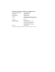
fold Register now to be included in our Preferred Customer Database! You'll receive new product information and product updates. Take a few minutes to fill out this registration card-postage is paid. Thank you! ADTRAN provides a broad line of end-user equipment that supports a wide range of business applications for host and remote sites including: ISDN terminal adapters, inverse multiplexers, NT1s, 56k DDS DSU/CSUs, T1 DSU/ CSUs, and multiplexers.
Express XR/XRT™ Warranty Registration Card Date Purchased: _________________________________ Part Number: ____________________________________ Model purchased: XR XRT Serial Number: __________________________________ Where did you purchase: ________________________ Where do you use a computer: (check all that apply) Office Home On the Road Where will this ISDN modem be used: Business Home Home business Elementary School High School College/University Federal Government State/Local Government What is the