
User's Manual

2 61287782F1-22A
3. Thread the fiber cable through the opening in the base. If there is
excess fiber, carefully wrap it around the Fiber Tray.
4. Remove the dust cover plug from the SC/APC Connector and
insert the fiber cable. Retain the dust cover and insert it in the fiber
connection when the fiber cable is not connected. This will protect
the optical portion of the connection.
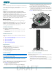
5. Figure 2 illustrates the 434RG ONT after the base has been attached.
Figure 1. Attach 434RG ONT to Base and Connect Fiber
Figure 2. 434RG ONT with Base Attached
Step 2: Connect POTS (PHONE)
If POTS cables are not available, use Figure 3 and the following procedure
to create the POTS cables:
1. Trim the insulation for the subscriber POTS cables.
2. Refer to Figure 3 and connect the twisted-pair Tip (green) and Ring
(Red) to the RJ-11 connector using an RJ-11 crimper.
3. Insert the RJ-11 connector in the appropriate PHONE 1 or PHONE 2
jack.
Screw
Fiber
Tray
SC/APC
Connector
Fiber
Opening
1
2
2.4
5.0
1
2
3
4
WPS
RF
CATV
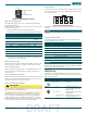
Cable Television (CATV) is television service that provides cable Internet
service with television to customers over the same links - normally coaxial
cable. CATV operates at a frequency of 54-870 MHz.
MoCA 2.0
Multimedia over Coax Alliance (MoCA) is an industry standard
technology for connecting the home to a service provider. MoCA
technology uses existing coaxial cabling for distributing high definition
video with multi-room applications such as DVRs.
The 434RG ONT supports MoCA Version 2.0 and is backward compatible
to MoCA Version 1.1. MoCA 2.0 operates in C4 and D bands with a
frequency range from 1125 to 1500 MHz. Channel bandwidth throughput
increased from > 140 Mb/s (MoCA 1.1) to 400 Mb/s. MoCA 2.0.
INSTALLATION
After unpacking the 434RG ONT, inspect it for damage. If damage is
noted, file a claim with the carrier and then contact ADTRAN. For more
information, refer to the warranty.
Installation consists of positioning the 434RG ONT on a desktop and
connecting POTS (PHONE), Ethernet, Fiber, and Power.
Installation Guidelines
The following are guidelines for this installation.
■ Read all warnings and cautions before installing or servicing the
434RG ONT
.
■ Do not locate the 434RG ONT in direct sunlight or next to any
thermal devices.
Installation Overview
To install the 434RG ONT, you will need to complete the following
steps:
■ “Step 1: Attach the 434RG ONT to the Base and connect Fiber”
■ “Step 2: Connect POTS (PHONE)”
■ “Step 3: Connect Ethernet”
■ “Step 4: Connect Power”
■ “Step 5: Connect USB”
■ “Step 6: Connect Coaxial Cable”
■ “Step 7: Connect UPS (optional)”
Required tools
Standard technician tools and those listed below are required for
installing the 434RG ONT.
■ PON power meter with wavelength filtering
■ Fiberscope or videoscope
For fiber optic connections, the following is required:
■ ODC Fiber cleaning tool
Installation Steps
NOTICE
The 434RG ONT must sit upright using the stand provided. DO NOT
lay the ONT flat as it may overheat.
Step 1: Attach the 434RG ONT to the Base and connect
Fiber
Ensure the 434RG ONT is not located in direct sunlight and is not located
next to any thermal obstructions. To attach the 434RG ONT to the base,
refer to Figure 1 and complete the following steps:
1. Position the 434RG ONT on the base.
2. Using the screw provided, secure the base to the 434RG ONT.
DRAFT