
User's Manual

61287782F1-22A 3
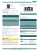
Figure 3. POTS (PHONE) Connection
Step 3: Connect Ethernet
The 434RG ONT supports four, CAT 6, 1 Gigabit (10/100/1000Base-T)
connections (GE 1 to GE 4).
If Ethernet cables are not available, use the following procedure and table
to create the Ethernet cables:
1. Trim the insulation for the subscriber Ethernet cable.
2. Connect the wires per the following table using an RJ-45 Crimper.
3. Insert the CAT 6 rated cable in the appropriate GE 1 through GE 4
ports on the rear of the 434RG ONT.
Step 4: Connect Power
Plug the supplied 12 VDC Power Adapter into the 12V connection on the
rear of the chassis. Connect the AC plug to a standard 120 VAC outlet.
Step 5: Connect USB
There is a USB data connection on the rear of the 434RG ONT that can be
used for connection and communications with other computers and
electronic devices.
Step 6: Connect Coaxial Cable
The coaxial connection is located on the rear of the 434RG ONT. Connect a
standard coaxial cable from this connection to the coaxial connection on
the television where you want Internet capability.
Step 7: Connect UPS (optional)
CAUTION
!
DO NOT connect the Power Adapter and an UPS at the same time as this
will cause damage to the 434RG ONT. The ONT can be powered by either
power source, but not both simultaneously.
The 434RG ONT can typically use an un-interruptible power supply
(UPS) if desired. Power is supplied to the 434RG ONT by a local power
source with battery backup that utilizes the AC power at the customer
premises. The UPS powers the 434RG ONT and functions as a battery
backup unit (BBU) supplying continuous 12 VDC. Refer to the installation
material that is provided with the UPS when installing the BBU.
Ethernet RJ-45 Pin-out
Pin Name Description Color Code
1 TRD0+ Transmit/Receive Positive White/
Orange
2 TRD0- Transmit/Receive Negative Orange
3 TRD1+ Transmit/Receive Positive White/Green
4 TRD2+ Transmit/Receive Positive Blue
5 TRD2- Transmit/Receive Negative White/Blue
6 TRD1- Transmit/Receive Negative Green
7 TRD3+ Transmit/Receive Positive White/Brown
8 TRD3- Transmit/Receive Negative Brown
1 2 3 4
1 = Not Connected
2 = Tip
3 = Ring
4 = Not connected
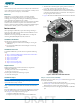
UPS Connector
Connect the UPS to the 8-pin MOLEX connector labeled “UPS” located on
the rear of the SFU ONT chassis. Figure 4 illustrates the MOLEX connector
on the rear of the ONT.
Figure 4. 8-Pin Molex Connector
The UPS Power/Alarm Connections Table below defines each pin on the
connector.
NOTE
ADTRAN offers a UPS Cable assembly (P/N 1287402G1) for this
connector.
UPS Power/Alarm Table
The following table indicates which pin is associated with each alarm
provided through a UPS connection.
NOTE
If an UPS is being used and is disconnected, the 434RG ONT will not
function and is not protected from power outages. In addition, a “Battery
Missing” alarm will be sent to the OLT.
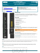
LED STATUS
The LEDs are located beneath the plastic housing and are only visible
after power has been applied. The following table provides the LED status
during normal operations.
Pin-Out Description Alarm
1 Power Input (+12 VDC) -
2UPS Status - On Battery1
3 UPS Status - Battery Missing 2
4 Signal Return -
5Power 12 V Return-
6 UPS Status - Replace Battery 3
7 UPS Status - Low Battery 4
8 No Connection -
Label Status Indication
POWER
Off
Green
AC or battery off
No Failure
FIBER
2
Off
Green
Green Flashing
Fast
No connection to the OLT,
open fiber, failure at the ONT,
or power is Off
DS signal present and is within
operating range
Ranging in Progress or AOE
Auto-upgrade in progress
87 6 5
4
3
4321
DRAFT