Total Access 900 Series Hardware Installation Guide Total Access 912 Total Access 916 Total Access 924 61210916L1-34A May 2005
Trademarks Total Access 900 Series Hardware Installation Guide Trademarks Any brand names and product names included in this manual are trademarks, registered trademarks, or trade names of their respective holders. Total Access® is a registered trademark of ADTRAN, Inc. To the Holder of the Manual The contents of this manual are current as of the date of publication. ADTRAN reserves the right to change the contents without prior notice.
Total Access 900 Series Hardware Installation Guide Conventions Conventions Notes provide additional useful information. Cautions signify information that could prevent service interruption or damage to equipment. Warnings provide information that could prevent endangerment to human life. 61210916L1-34A Copyright © 2005 ADTRAN, Inc.
Safety Instructions Total Access 900 Series Hardware Installation Guide Safety Instructions When using your telephone equipment, please follow these basic safety precautions to reduce the risk of fire, electrical shock, or personal injury: 1. Do not use this product near water, such as a bathtub, wash bowl, kitchen sink, laundry tub, in a wet basement, or near a swimming pool. 2. Avoid using a telephone (other than a cordless-type) during an electrical storm.
Total Access 900 Series Hardware Installation Guide FCC-Required Information FCC-Required Information FCC regulations require that the following information be provided in this manual: 1. This equipment complies with Part 68 of FCC rules and requirements adopted by ACTA. Each registered interface has a label that contains, among other information, a product identifier in the format US:AAAEQ##TXXXX. If requested, provide this information to the telephone company. 2.
FCC Radio Frequency Interference Statement Total Access 900 Series Hardware Installation Guide FCC Radio Frequency Interference Statement This equipment has been tested and found to comply with the limits for a Class A digital device, pursuant to Part 15 of the FCC Rules. These limits are designed to provide reasonable protection against harmful interference when the equipment is operated in a commercial environment.
Total Access 900 Series Hardware Installation Guide Industry Canada Compliance Information Industry Canada Compliance Information Notice: The Industry Canada label applied to the product (identified by the Industry Canada logo or the “IC:” in front of the certification/registration number) signifies that the Industry Canada technical specifications were met. Notice: The Ringer Equivalence Number (REN) for this terminal equipment is supplied in the documentation or on the product labeling/markings.
Affidavits Total Access 900 Series Hardware Installation Guide Affidavits Affidavit Requirements for Connection to Digital Services • An affidavit is required to be given to the telephone company whenever digital terminal equipment without encoded analog content and billing protection is used to transmit digital signals containing encoded analog content which are intended for eventual conversion into voiceband analog signals and transmitted on the network.
Total Access 900 Series Hardware Installation Guide Affidavits Affidavit for Connection Of Customer Premises Equipment to 1.
Warranty and Customer Service Total Access 900 Series Hardware Installation Guide Warranty and Customer Service ADTRAN will repair and return this product within the warranty period if it does not meet its published specifications or fails while in service. Warranty information can be found at: http://support.adtran.com (Click on Warranty and Repair Information, under Support.) Product Registration Registering your product helps ensure complete customer satisfaction.
Total Access 900 Series Hardware Installation Guide Product Support Information Pre-Sales Inquiries and Applications Support Your reseller should serve as the first point of contact for support. If additional pre-sales support is needed, the ADTRAN Support website provides a variety of support services such as a searchable knowledge base, latest product documentation, application briefs, case studies, and a link to submit a question to an Applications Engineer.
Product Support Information Total Access 900 Series Hardware Installation Guide Training The Enterprise Networks (EN) Technical Training Department offers training on our most popular products. These courses include overviews on product features and functions while covering applications of ADTRAN's product lines. ADTRAN provides a variety of training options, including customized training and courses taught at our facilities or at your site.
Table of Contents Introduction to the Total Access 900 Series . . . . . . . . . . . . . . . . . . . . . . . . . . . . . . . . . . . . . . . 19 Features and Specifications . . . . . . . . . . . . . . . . . . . . . . . . . . . . . . . . . . . . . . . . . . . . . . . . . . . . 19 Unpack and Inspect the System . . . . . . . . . . . . . . . . . . . . . . . . . . . . . . . . . . . . . . . . . . . . . . . . . 20 Contents of ADTRAN Shipments . . . . . . . . . . . . . . . . . . . . . . . . . . . . . . . . . . . . .
Table of Contents 14 Total Access 900 Series Hardware Installation Guide Copyright © 2005 ADTRAN, Inc.
List of Figures Figure 1. Figure 2. Figure 3. Figure 4. Figure 5. Total Access 900 Series Front Panel Layouts. . . . . . . . . . . . . . . . . . . . . . . . . . . . . . . . . . . . . Total Access 900 Series Rear Panel Layout . . . . . . . . . . . . . . . . . . . . . . . . . . . . . . . . . . . . . . Voice Connector Pin Assignments . . . . . . . . . . . . . . . . . . . . . . . . . . . . . . . . . . . . . . . . . . . . . Wallmounting the Unit . . . . . . . . . . . . . . . . . . . . . . . . . . . . . . . . .
List of Figures 16 Total Access 900 Series Hardware Installation Guide Copyright © 2005 ADTRAN, Inc.
List of Tables Table 1. Table 2. Table A-1. Table A-2. Table A-3. Table A-4. Table A-5. Table B-1. Table B-2. Table B-3. Total Access 900 Series LEDs . . . . . . . . . . . . . . . . . . . . . . . . . . . . . . . . . . . . . . . . . . . . . . . . Battery Pack Specifications . . . . . . . . . . . . . . . . . . . . . . . . . . . . . . . . . . . . . . . . . . . . . . . . . . VOICE Connector. . . . . . . . . . . . . . . . . . . . . . . . . . . . . . . . . . . . . . . . . . . . . . . . . . . . . . . . . .
List of Tables 18 Total Access 900 Series Hardware Installation Guide Copyright © 2005 ADTRAN, Inc.
1. INTRODUCTION TO THE TOTAL ACCESS 900 SERIES The Total Access 900 Series products are Integrated Access Devices (IAD) designed for cost-effective deployment of up to 1.536 Mbps of Session Initiation Protocol (SIP), PPP, or Frame Relay voice and data services. The Total Access 900 Series combines voice and data services into a single platform creating the 4th generation of ADTRAN IADs for IP Telephony service providers (such as CLECs, ILECs, and ISPs).
Introduction to the Total Access 900 Series Total Access 900 Series Hardware Installation Guide This hardware installation guide describes the Total Access 900 Series units, details basic functionality, gives installation instructions, and lists unit specifications. For more information on a specific application, refer to the quick start documents provided on your ADTRAN OS Documentation CD.
Total Access 900 Series Hardware Installation Guide 2. Physical Description PHYSICAL DESCRIPTION Reviewing the Front Panel Design Figure 1 shows the Total Access 900 Series products front panels (the Total Access 912 contains twelve FXS ports, the Total Access 916 contains sixteen FXS ports, and the Total Access 924 contains twentyfour FXS ports). TOTAL ACCESS 912 Total Access 912 TOTAL ACCESS 916 Total Access 916 TOTAL ACCESS 924 Total Access 924 Figure 1.
Physical Description Total Access 900 Series Hardware Installation Guide Front Panel LEDs Table 1 describes the front panel LEDs. Table 1. Total Access 900 Series LEDs For these LEDs… This activity… Indicates that… Off Bootstrap mode - The boot code cannot be booted. During Bootstrap mode, VOICE, DATA, NET, and DSX-1 LEDs will be red. Green (flashing) Unit is powering up.
Total Access 900 Series Hardware Installation Guide Physical Description Reviewing the Rear Panel Design Figure 2 shows the Total Access 900 Series products’ rear panel, which contain identical interfaces regardless of the model (Total Access 912/916/924). Figure 2. Total Access 900 Series Rear Panel Layout Rear Panel Interfaces and LEDs Power Supply The Total Access 900 Series products have a 90-120 VAC power supply with an IEC connector. The appropriate three-prong cable is included in the shipment.
Physical Description Total Access 900 Series Hardware Installation Guide VOICE Connection A single 50-pin female amphenol connector provides the interconnect wiring for the analog circuits (FXS). Figure 3 shows the VOICE connector pinout.
Total Access 900 Series Hardware Installation Guide 3. Unit Installation UNIT INSTALLATION The instructions and guidelines provided in this section cover hardware installation topics such as wallmounting/rackmounting the unit and installing the unit. See Unpack and Inspect the System on page 20 before getting started.
Unit Installation Total Access 900 Series Hardware Installation Guide Mounting Options The Total Access 900 Series may be installed in a wallmount, rackmount, or tabletop configuration. The following sections provide step-by-step instructions for rackmounting and wallmounting. Wallmounting Total Access 900 Series Instructions for Wallmounting Total Access 900 Series Step Action 1 Attach the wallmount brackets to the unit using the supplied screws.
Total Access 900 Series Hardware Installation Guide Unit Installation Rackmounting Total Access 900 Series The Total Access 900 Series products are housed in a 1U-high, rackmountable chassis which can be installed into 19-inch or 23-inch equipment racks. For a rackmount installation, optional rackmount brackets must be purchased (19” – P/N 1200927L19, 23” – P/N 1200927L23). The Total Access 912/916/924 mount and connect with standard fasteners and hand tools.
Unit Installation Total Access 900 Series Hardware Installation Guide Grounding for AC Power The attachment-plug receptacles in the vicinity of the product or system are all to be of a grounding type, and the equipment grounding conductors serving these receptacles are to be connected to earth ground at the service equipment. Supplying Power to the Unit As shipped, each Total Access 900 Series product is set to factory default conditions.
Total Access 900 Series Hardware Installation Guide 4. Battery Backup Unit BATTERY BACKUP UNIT The ADTRAN Battery Backup Unit is an optional device designed as a backup DC power supply for the Total Access 900 Series. The Battery Pack connects to the Total Access 900 Seriesthrough a 6-foot charge/ discharge, 2-conductor wire with a keyed modular plug (included with the Battery Backup Unit). The 1175044L1 Battery Backup Unit is a low profile wallmount configuration.
Battery Backup Unit Total Access 900 Series Hardware Installation Guide • This device may not cause harmful interference • This device must accept any interference received, including that which may cause undesired operation Wallmounting the Battery Pack Figure 5 shows the Battery Pack mounting dimensions. Figure 5. Battery Pack Mounting Dimensions For a wallmount installation, the Battery Pack installs on heavy plywood (3/4-inch minimum) using four #10 x 3/4-inch pan-head wood screws.
Total Access 900 Series Hardware Installation Guide Battery Backup Unit Maintenance • The Battery Pack does not require routine maintenance for normal operation. The life expectancy of the Battery Pack is 3 to 5 years on standby use when used at room temperature. • Excessive heat decreases battery power and life. Ideal ambient temperature for battery life and capacity is 20°C. Extreme low temperature also decreases battery capacity. • Battery shelf life is extended in cooler temperatures.
Battery Backup Unit 32 Total Access 900 Series Hardware Installation Guide Copyright © 2005 ADTRAN, Inc.
Appendix A. PIN ASSIGNMENTS Table A-1.
Appendix A Total Access 900 Series Hardware Installation Guide Table A-2. DSX-1 (T1 0/2) Pin Name Description 1 R Transmit data toward the DTE (Ring) 2 T Transmit data toward the DTE (Tip) 3 Unused — 4 R1 Receive data from the DTE (Ring) 5 T1 Receive data from the DTE (Tip) 6-8 Unused — Table A-3.
Total Access 900 Series Hardware Installation Guide Appendix A Table A-5.
Appendix A 36 Total Access 900 Series Hardware Installation Guide Copyright © 2005 ADTRAN, Inc.
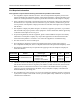
APPENDIX A. ADTRAN OS SUPPORTED MIBS ADTRAN AOS platforms support the MIBs listed in Table B-1. For the most up-to-date MIB list, please visit our website at www.adtran.com. Table B-1. MIBs Supported in the AOS Name RFC DS1-MIB 2495 Describes DS1, E1, DS2, and E2 interface objects. 1 Ether-like-MIB 2665 Describes generic objects for Ethernet-like network interfaces. 2 FRAME-RELAY-DTE-MIB 2115 Describes the use of a Frame Relay interface by a DTE.
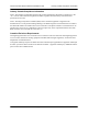
Appendix B Total Access 900 Series Hardware Installation Guide Table B-2.
Total Access 900 Series Hardware Installation Guide Appendix B Table B-2.
Appendix B Total Access 900 Series Hardware Installation Guide Table B-2.
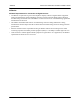
Total Access 900 Series Hardware Installation Guide Appendix B Table B-3. Traps Supported in the AOS Name OID Cold Start 1.3.6.1.6.3.1.1.5.1 Warm Start 1.3.6.1.6.3.1.1.5.2 Link Down 1.3.6.1.6.3.1.1.5.3 Link Up 1.3.6.1.6.3.1.1.5.4 Authentication Failure 1.3.6.1.6.3.1.1.5.5 61210916L1-34A Copyright © 2005 ADTRAN, Inc.
Appendix B 42 Total Access 900 Series Hardware Installation Guide Copyright © 2005 ADTRAN, Inc.
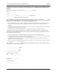
Total Access 900 Series Hardware Installation Guide Index INDEX N A NET T1 0/1 23 pinout 34 AC power 28 affidavits 8 P B power 28 power supply 23 product registration 10 battery backup unit 29 specifications 31 C contents of shipment 20 craft port EIA-232 serial port (DCE) 23 pinouts 35 customer service 10 D DSX-1 (T1 0/2) 23 pinout 34 E ethernet interface 10/100BaseT 23 pinout 34 exclusions (MIBs) 38 F features of the Total Access 900 Series 19 front panel 21 R rackmounting 27 rear panel 23
Index 44 Total Access 900 Series Hardware Installation Guide Copyright © 2005 ADTRAN, Inc.