Adtron Corporation I35MB - 3.5” Mirrored Hard Disk Operations Manual March 2006 Rev.
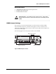
ESD Warning Before handling the I35MB, or any media associated with the I35MB, ensure that you are working in an ESD-safe environment. Notice This manual describes the features of the Adtron I35MB. Adtron reserves the right to modify, amend, or in any way change the contents and/or products described herein, at any time, without notification. The information contained in this document is provided for reference only.
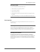
Table of Contents Introduction 1 Aborting a button press I35MB Features 1 Related Documents 2 I35MB Jumper Settings 2 Setting Master/Slave and Cable Select 3 Setting a Remote-Mounted Activity LED 3 Interface Connectors 4 I35MB Installation 4 Introduction 4 Inserting the I35MB 5 Removing the I35MB 6 Basic Operation 6 Operating System Installation 6 I35MB LEDs and Mirror Control Buttons 7 Mirror Control Button Functions 8 Advanced Operations Using the I35MB Rail Kit 15 S.M.A.
Adtron I35MB Operations Manual Introduction The Adtron™ Diskpak™ Model I35MB with Adtron ActiveRAID™ technology incorporates RAID-1 mirroring in a 3.5-inch hard disk form factor. RAID-1 mirroring between two hard disk drives provides data redundancy and rebuild independent from the host CPU. With both disk drives functioning properly, the I35MB keeps both disk drives automatically updated.
Adtron I35MB Operations Manual Related Documents • • • ANSI NCITS 340-2000 ATA/ATAPI-5 Specification I35MB Product Specification I35MB Installation Manual Static Sensitive – The I35MB is a static sensitive device. While setting jumpers, take precautions to ensure that static does not discharge into the I35MB. I35MB Jumper Settings The master/slave and remote LED jumper is located on the front of the I35MB, between the IDE and power connectors.
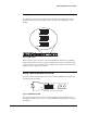
Adtron I35MB Operations Manual Setting Master/Slave and Cable Select This IDE jumper is only for the configuration of master, slave, cable select and to mount a remote Activity LED. Figure 3 shows the pins of the IDE jumper on the I35MB. 7 5 3 1 8 6 4 2 Master Setting 7 5 3 1 8 6 4 2 Slave Setting 7 5 3 1 8 6 4 2 Cable Select Setting Figure 3 IDE Jumper When a jumper is placed on pins 3 and 4, the I35MB is the master device (default).
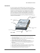
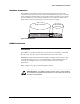
Adtron I35MB Operations Manual Interface Connectors The I35MB has an interface connector located on the front panel. Using an 80conductor cable (40-pin connector); connect the I35MB to the primary or secondary ports on the IDE controller. Plug a power cable from the computer’s power supply into the I35MB power connector. The I35MB does not require 12V. Refer to the Figure below, for the location 40-pin connector and power supply.
Adtron I35MB Operations Manual Inserting the I35MB To install the I35MB in the hard disk drive bay: 1. Power down the computer and remove the cover. 2. Make sure that you are properly grounded. 3. Set the master/slave to desired configurations. By default, the I35MB is set to master. 4. Select a 3.5-inch drive bay that houses either a floppy or hard disk. If the chassis provides a front removable panel, the buzzer reset and fault LEDs can be viewed by removing the plastic panel on the chassis. 5.
Adtron I35MB Operations Manual Removing the I35MB To remove the I35MB from the hard disk drive bay: 1. Make sure that you are properly grounded. 2. Power down the computer. 3. Remove the chassis casing. 4. Disconnect the 80-conductor cable and the computer power supply cable from the I35MB. 5. Unfasten the mounting screws and remove the I35MB from the disk drive bay. Basic Operation The I35MB operates as a storage subsystem that can be used as a boot device or as additional storage.
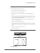
Adtron I35MB Operations Manual I35MB LEDs and Mirror Control Buttons Activity LED Bank 0 Fault LED D12 D10 Bank 1 Access LED Bank 0 Access LED D13 Bank 1 Fault LED D11 D14 S4 Buzzer Reset S2 Bank 0 Mirror Control S3 Bank 1 Mirror Control Figure 7 LEDs and Mirror controls The LEDs are used to indicate individual Bank status (access/fault), media activity (read/writes) and Mirror status. Table 1 describes LED states, mirror status and controls.
Adtron I35MB Operations Manual Mirror Control Button Functions The following figure shows the location of the mirror control buttons and LEDs on the I35MB. Bank 1 Mirror control Buzzer Reset Bank 0 Mirror control Figure 8 Mirror Control Button operations The following table describes the different operations using the Mirror Control button on either bank. Press and hold Mirror Control button to activate the functions listed in Table 2.
Adtron I35MB Operations Manual Adtron recommends having a system back-up available prior to managing hard or soft faults. Bank Hard Faults Hard fault errors may originate from any one of the following: • Write errors • Track 0 Not Found read error • HDD Timeout after a command If a hard fault occurs on one bank, the I35MB continues to read and write data to the other functioning bank. The I35MB is running in a degraded mode, which should be corrected as soon as possible.
Adtron I35MB Operations Manual Rebuilding the faulted drive may take several hours, depending on the size of the media and may result in a hard fault if the drive cannot “map” around any “bad” sectors. While rebuilding can result in a reliable storage device and workable drive, Adtron recommends replacing the drive in the field that exhibits a soft fault and then rebuilding and testing this drive in a noncritical test environment to determine if this drive can be used as a spare.
Adtron I35MB Operations Manual 3. Note the bank number, 0 or 1, with the fault LED turned solid orange. This is the bank that requires attention. 4. Power down the computer. 5. Remove the computer cover and locate the I35MB in the disk drive bay. 6. Disconnect the power supply and 80-conductor cable from the I35MB. 7. Unscrew the chassis mounting screws and slide the I35MB out of the disk drive bay. 8. On the side opposite the flex cables, loosen the retaining screw for the faulted disk drive.
Adtron I35MB Operations Manual 12. Before the disk drive is fully seated (approximately ¼ of an inch to the drive being fully seated) re-attach the flex cable to the disk drive. Refer to Figure 10 for a view of this procedure. Carefully align and slowly attach. Pay close attention to mounting the flex cable. Ignoring this procedure and caution can lead to damage in future operations. 13. Tighten the retaining screw for the new disk drive. 14.
Adtron I35MB Operations Manual Rebuilding a bank After a bank has been replaced, a rebuild must be performed. To start a Bank Rebuild, press the mirror control button between 5 and 10 seconds on the off-line bank. Release the button when the Access LED starts flashing at 2 blinks per second. The rebuild process begins, indicated by the Access LED turning solid green and the Fault LED flashing green. When complete, the Fault LED changes from flashing green to off.
Adtron I35MB Operations Manual Examples: A new I35MB is installed in the field with two 20GB capacity media for 20GB of mirrored storage. Bank 1 requires replacement. A 10GB media is installed and the button pressed for rebuild. Rebuild will not start and the mirror remains broken. A 40GB media is then inserted in Bank 1. The rebuild copies the data from the Bank 0 20GB drive to the new drive in Bank 1. The I35MB remains a 20GB mirrored device. Bank 0 media is replaced with a 60GB unit.
Adtron I35MB Operations Manual Using the I35MB Rail Kit The following steps describe the process to disassemble and reassemble hard disk drives on the I35MB. Attention to individual instructions is necessary to ensure functionality and avoid damage to the device. Please contact Adtron Sales if assembling hard disk drives other than those provided by Adtron, and refer to the section of this manual titled, Using Different Size Media.
Adtron I35MB Operations Manual S.M.A.R.T. (Self-Monitoring, Analysis and Reporting Technology) Attributes The Adtron Diskpak I35MB incorporates an array of S.M.A.R.T. attributes and capabilities that provide significant amounts of information relating to the life history of the hard disk drive (HDD). S.M.A.R.T. is a monitoring system for computer (HDDs) to detect and report on various indicators of reliability, with the intent of anticipating failures.
Adtron I35MB Operations Manual S.M.A.R.T Attribute Table S.M.A.R.T attributes are vendor specific parameters that are used in evaluating the status of the device. Adtron specific S.M.A.R.T attributes are listed below. Many tools used to display S.M.A.R.T. attributes may not recognize Adtron specific attributes. Refer to Table 3 to identify Adtron specific S.M.A.R.T. attributes.
Adtron I35MB Operations Manual Attribute Number (8 bits) 194 (0xC2) 199 (0xC7) Name Value (8 bits) Raw Data (eight, 8-bit bytes) Threshold Temperature Degrees C (Note 194) 0 UltraDMA error count 0 Unsigned integer 0 (Note 199) Table 3 S.M.A.R.T. Attributes S.M.A.R.T Attribute Notes Note Description 110 This value does not conform to the ATTRIBUTE value/threshold model. The value literally indicates the number of members in each mirror set.
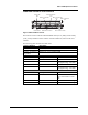
Adtron I35MB Operations Manual LED Indicators IDLE State – No host access Bank Access LED (Green/Orange) Bank Fault LED (Green/Orange) Drive Activity LED (Green/Orange) GREEN GREEN flashing (1/sec) OFF OFF OFF OFF GREEN GREEN OFF ORANGE GREEN GREEN GREEN flashing (1/sec) OFF See Note 1 GREEN OFF ORANGE OFF ORANGE GREEN Drive reinserted OFF Request rebuild GREEN flashing (2/sec) Rebuilding GREEN ORANGE See Note 1 GREEN GREEN Rebuild complete Soft Fault GREEN OFF GREEN GREEN GREEN H
Adtron I35MB Operations Manual ACTIVE State – Host access Bank State Bank Access LED (Green/Orange) Bank Fault LED (Green/Orange) Drive Activity LED (Green/Orange) Normal GREEN OFF ORANGE OFF ORANGE OFF ORANGE OFF See Note 1 ORANGE ORANGE OFF ORANGE ORANGE ORANGE ORANGE ORANGE See Note 1 ORANGE GREEN flashing (2/sec) ORANGE Request off-line GREEN flashing (1/sec) Becoming offGREEN line Fully off-line OFF Request on-line GREEN flashing (1/sec) Becoming onOFF line Drive removed OFF Driv
Adtron I35MB Operations Manual I35MB Dimension Drawings 25.3 .997 146.1 5.750 6-32 x 3.8[.150] MAX. DEPTH (3X) 101.6 4.000 Figure 11 I35MB 21 Rev.
Adtron I35MB Operations Manual Appendix I The table below lists the parts supplied on the I35MB Rail Kit. Items numbers correspond with Figure 11, under the section of this document titled, Using the I35MB Rail Kit. Item Number Quantity Description #1 #2 #3 #4 #5 Four (4) One (1) One (1) One (1) Two (2) Rail Retention Screw (M3 x 5) Rail – Left Rail – Right Drive Assembly Retention Screw (M2. 5x9) Chassis Ground Protection Barrier Table 7 Parts Supplied 22 Rev.
Adtron I35MB Operations Manual Sales and Technical Support Contact Adtron Corporation for technical support, application questions, data sheets, and documentation. Our normal business hours are Monday through Friday, 8am to 5pm, MST. Headquarters – Sales Europe - Sales Adtron Corporation 4415 E. Cotton Center Blvd. Phoenix, AZ 85040 Tel: +1-602-735-0300 Fax: +1-602-735-0359 Web: http://www.adtron.com Email: sales@adtron.com Tel: +41-56-496-5640 Fax: +41-56-496-5648 Email: eurosales@adtron.
Adtron I35MB Operations Manual Revision Control Rev Author Date Sections Description 001 002 003 JMH JMH JMH Apr 2005 Aug 2005 Mar 2006 All Connector SMART, Rail Kit Original 8-pin change to the connector Adding SMART attributes/ and information. Rail Kit guide. 24 Rev.