ATLAS 800PLUS USER MANUAL Part Number 1200226L1 61200226L1-1A September 1998
TRADEMARKS: Windows is a registered trademark of Microsoft Corporation. DMS 100 is a registered trademark of Northern Telecom. 5ESS is a registered trademark of Lucent. Lucent Technologies is a registered trademark. 901 Explorer Boulevard P.O. Box 140000 Huntsville, AL 35814-4000 (256) 963-8000 © 1998 ADTRAN, Inc. All Rights Reserved. Printed in U.S.A.
ABOUT THIS MANUAL The ATLAS 800PLUS system consists of the Base Unit and one or more modules. Each ATLAS 800PLUS option module includes its own User Manual, containing specific information about installing, configuring, and testing the module. This manual includes information you need to install, configure, test, and troubleshoot an ATLAS 800PLUS system, often referring you to the individual module manual when applicable. This manual is arranged so you can quickly and easily find the information you need.
FCC regulations require that the following information be provided to the customer in this manual: 1. 2. 3. 4. 5. 6. 7. iv This equipment complies with Part 68 of the FCC rules. The required label is affixed to the bottom of the chassis. An FCC compliant telephone cord and modular plug are provided with this equipment. This equipment is designed to be connected to the telephone network or premises wiring using a compatible modular jack which is Part 68 compliant.
FEDERAL COMMUNICATIONS COMMISSION RADIO FREQUENCY INTERFERENCE STATEMENT This equipment has been tested and found to comply with the limits for a Class A digital device, pursuant to Part 15 of the FCC Rules. These limits are designed to provide reasonable protection against harmful interference when the equipment is operated in a commercial environment.
AFFIDAVIT REQUIREMENTS FOR CONNECTION TO DIGITAL SERVICES vi • An affidavit is required to be given to the telephone company whenever digital terminal equipment without encoded analog content and billing protection is used to transmit digital signals containing encoded analog content which are intended for eventual conversion into voiceband analog signals and transmitted on the network.
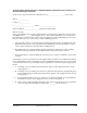
AFFIDAVIT FOR CONNECTION OF CUSTOMER PREMISES EQUIPMENT TO 1.544 MBPS AND/ OR SUBRATE DIGITAL SERVICES For the work to be performed in the certified territory of ________________________(telco name) State of ________________ County of ________________ I, _____________________________ (name), _____________________ (business address), ____________________ (telephone number) being duly sworn, state: I have responsibility for the operation and maintenance of the terminal equipment to be connected to 1.
I agree to provide ______________________ (telco’s name) with proper documentation to demonstrate compliance with the information as provided in the preceding paragraph, if so requested.
CANADIAN EQUIPMENT LIMITATIONS The Industry Canada Certification label identifies certified equipment. This certification means that the equipment meets certain telecommunications network protective, operational, and safety requirements. The Department does not guarantee the equipment will operate to the user's satisfaction. Before installing this equipment, users should ensure that it is permissible to be connected to the facilities of the local telecommunications company.
x ATLAS 800PLUS User Manual 61200226L1-1
Table of Contents List of Figures ................................................................................................................................................ xv List of Tables............................................................................................................................................... xvii Chapter 1 Introduction..............................................................................................................................
Table of Contents Power Up Testing And Initialization ......................................................................................................... 2-7 Self-Test .............................................................................................................................................2-7 Chapter 3 Operation ..................................................................................................................................3-1 Front Panel Layout....................
Table of Contents Quad T1/PRI Module (User Termination/PRI) ............................................................... 5-46 Quad T1/PRI Module (User Termination/RBS) .............................................................. 5-48 Quad Nx56/64 Module Interface Configuration...................................................................... 5-49 Quad Nx56/64 Module (User Termination) ..................................................................... 5-50 Octal BRI Module Configuration ........
Table of Contents Appendix C Warranty and Technical Support Information..............................................................C-1 Index ......................................................................................................................................................
List of Figures Figure 1-1. Point-to-Point Circuit.............................................................................................................. 1-2 Figure 1-2. Frame Relay Circuit ................................................................................................................ 1-3 Figure 1-3. Digital Access Cross-Connect System (DACS) ................................................................... 1-4 Figure 1-4. T1 Bandwidth Management ...................................
List of Figures xvi ATLAS 800PLUS User Manual 61200226L1-1
List of Tables Table 2-1. Table 2-2. Table 2-3. Table 2-4. Table 6-1. Table 7-1. Table 7-2. Table 9-1. Table 9-2. Table 9-3. Table 9-4. Table 9-5. Table A-1. Table A-2. Table A-3. Table A-4. Table A-5. Table A-6. Table A-7. Table A-8. Table A-9. Table A-10. Table A-11. Table B-1. 61200226L1-1 Control In/Chain In Pinout ................................................................................................... 2-4 Control Out/Chain Out Pinout ........................................................
List of Tables xviii ATLAS 800PLUS User Manual 61200226L1-1
Introduction Chapter 1 PRODUCT OVERVIEW The ATLAS_800PLUS is a modular, highly scalable platform that provides robust solutions for the wide area communication needs of medium-to-large corporations and network access providers. ATLAS is an Integrated Access System with the most extensive support of dedicated bandwidth management and access switching in the industry. The ATLAS_800PLUS is a high performance version of the ATLAS 800.
Chapter 1. Introduction The modules include the following: • Quad Nx 56/64 Module • Quad T1/PRI Module • Octal Basic Rate ISDN Module • T3 Module • Async-232 Module • Modem-16 Module Frame Relay Frame relay is a packet-switched service that allows efficient transfer of bursty traffic in a WAN environment. It offers lower-cost data transfer when compared to typical point-to-point applications.
Chapter 1. Introduction Frac T1 Frame Relay Figure 1-2. Frame Relay Circuit The Frame Relay/Router upgrade option adds the capability for the ATLAS series of Integrated Access Devices to act as a voice/data FRAD, a frame relay switch, and an IP router in addition to the current available bandwidth manager and switch applications. Dedicated and Switched Connection Maps in a Single Platform The ATLAS_800PLUS allocates dedicated bandwidth according to any of up to five unique connection maps.
Chapter 1. Introduction Flexible Network Management and Maintainability Several network management methods are available for the ATLAS_800PLUS, including SNMP support. VT 100 and Telnet are also offered, providing detailed system configuration through an easy-to-use menu system. The terminal interface is secured by six levels of password protection with varying degrees of management privileges.
Chapter 1. Introduction T1 Bandwidth Manager As a T1 Bandwidth Manager, ATLAS_800PLUS combines the functions of a T1 CSU/DSU, an intelligent channel bank, a T1 Multiplexer, and DACS into a single platform. The Bandwidth Manager supports a wide range of data applications including T1 “drop and insert,” channel grooming, and wide area data transport. ATLAS is ideal for point-to-point configurations or access to public networks.
Chapter 1. Introduction Figure 1-5.
Chapter 1. Introduction ISDN Switch Types • 5ESS™, DMS-100™, National ISDN Dedicated Connection Maps • Up to five connection maps • Time of day/day of week configurable • Preserves signaling through cross-connect • No effect on non-configured channels Switched Connection Maps • Inbound and outbound call filtering and blocking • Local and remote: payload/line, V.
Chapter 1.
Installation Chapter 2 BEFORE INSTALLING THE ATLAS_800PLUS Carefully inspect the ATLAS_800PLUS unit for shipping damage. If you suspect damage, file a claim immediately with the carrier and then contact ADTRAN Technical Support (see “Warranty and Technical Support Information” on page C1). If possible, keep the original shipping container for returning the ATLAS_800PLUS for repair or for verification of damage during shipment.
Chapter 2. Installation GROUNDING INSTRUCTIONS This section provides grounding instruction information from the Underwriters' Laboratory UL 1459 Standard for Safety: Telephone Equipment, of September 20, 1993. An equipment grounding conductor that is not smaller in size than the ungrounded branch-circuit supply conductors is to be installed as part of the circuit that supplies the product or system. Bare, covered, or insulated grounding conductors are acceptable.
Chapter 2.
Chapter 2. Installation Table 2-1. Control In/Chain In Pinout PIN NAME DESCRIPTION 1 GND Ground - connected to unit chassis 2 RTS Request to send - flow control 3 RXDATA Data received by the ATLAS_800PLUS 4 DTR Data terminal ready 5 TXDATA Date transmitted by the ATLAS_800PLUS 6 CD Carrier detect 7 UNUSED — 8 CTS Clear to send - flow control Control Out/Chain Out The Control Out/Chain Out is an RJ-48C port used to connect to another ATLAS_800PLUS Chain In connector.
Chapter 2. Installation Table 2-2. Control Out/Chain Out Pinout PIN 1 NAME DESCRIPTION GND Ground - connected to unit chassis. Connect to GND of next unit (pin1). 2 UNUSED — 3 TX DATA Data transmitted to chained units by the ATLAS. Connect to RX DATA of the next unit (chain in pin 3). 4 UNUSED — 5 RX DATA Data received from chained units by the ATLAS. Connect to TX DATA of the next unit (chain in pin 5).
Chapter 2. Installation Table 2-3. Network Pinout PIN NAME DESCRIPTION 1 R1 RXDATA-RING Receive data from the network 2 T1 RXDATA-TIP Receive data from the network 3 UNUSED — 4 R TXDATA-RING Send data toward the network 5 T TXDATA-TIP Send data toward the network UNUSED — 6,7,8 Ethernet 10BaseT Connection The 10BaseT port (RJ-48C) provides an Ethernet LAN connection, which is used for TFTP, SNMP, and Telnet connection. See Table 2-4 on page 2-6 for the pinout.
Chapter 2. Installation OPTION SLOT ARRANGEMENT SLOT 1 SLOT 5 SLOT 2 SLOT 6 SLOT 3 SLOT 7 SLOT 4 SLOT 8 POWER SUPPLY As viewed from the rear of the ATLAS_800PLUS, the slots are numbered as shown in Figure 2-2. All slots are functionally identical except slots 7 and 8, which also accommodate an optional power supply for redundancy. Figure 2-2.
Chapter 2. Installation 5. Board-to-board interface test. A test pattern is sent from the controller through a loopback on all other boards and checked on the controller. This verifies the data path, clocks, and control signals If the front panel indicates a failure, see Troubleshooting on page B-1 to diagnose the problem.
Operation Chapter 3 FRONT PANEL LAYOUT The ATLAS_800PLUS front panel provides limited control of the unit. You can select and set up the method of connectivity for controlling the unit through the front panel and use it to monitor the operation and status of the unit. Figure 3-1 on page 3-2 identifies the display panels and operation keys. LCD Window Displays menu items and messages in two lines by 16 characters in a backlit liquid crystal display (LCD). It also displays alarm and status information.
Chapter 3. Operation Enter Clear LCD Window Alarm Cancel System LED Module Status Module Status LEDs Home CSU Status LEDs Up and Down Arrows Shift Module Slot Numbers LCD Displays menu items and messages in 2 lines by 16 characters. Clear Clear data/results fields. Cancel Stops current activity and returns to the previous menu. CSU Status LEDs Indicate the status of both network interfaces. Home Returns to the main menu.
Chapter 3. Operation Operation Keys Operation keys are ATLAS 800 PLUS front panel keys that perform alternate functions. To activate an operation key, simultaneously press the front panel shift key and the operation key that you want to activate. To do this... Press these front panel keys... Quickly accesses the active alarm display menus. Shift + Alarm (This function can be activated while any other menu item is in use.
Chapter 3. Operation Channel Service Unit (CSU) Status The CSU Status LEDs indicate the status of both network interfaces. This color light... Indicates this CSU status... OK (green) Indicates normal, error-free operation of both network interfaces. If either interface experiences alarms, the OK LED remains off. Test (yellow) Indicates that one of the interfaces is operating in a test mode. This includes a self-test, a test pattern, or a test loopback.
Chapter 3. Operation OPERATING THE ATLAS 800 PLUS You can access basic setup functions from the ATLAS_800PLUS front panel. To access all of the ATLAS_800PLUS functions, set up a Telnet session or use a VT-100. The following sections provide an overview of the different ways to operate the ATLAS_800PLUS. After you understand the different ways to operate the ATLAS_800PLUS, you will be ready to configure the unit.
Chapter 3. Operation You can access the terminal menu using a VT-100 terminal or a computer running VT-100 terminal-emulation software. The two basic connection methods supported by the ATLAS_800PLUS are a direct connection through the EIA-232 Chain In port and a Telnet session. The following sections describe how to get started using both of these methods.
Chapter 3. Operation through the terminal menus. See “Access Passwords” on page 5-16 for details. The Telnet session will time out and display the Login prompt after a pre-defined time that is set in the Session Timeout option (see “Session Timeout” on page 5-12 for details). Use the Max Telnet Sessions option to define the number of Telnet sessions that can be active at one time (see “Max Telnet Sessions” on page 5-13 for details). Microsoft Telnet version 1.0 does not implement full VT-100 emulation.
Chapter 3. Operation T-Watch Pro T-Watch PRO is the ADTRAN Microsoft Windows management software program designed to control TSU units from a remote PC. It provides limited control over the configuration of the ATLAS_800PLUS using a graphic interface. Currently, you can choose ATLAS_800PLUS from a list of products, and T-Watch PRO automatically initiates a Telnet session by which you can connect to and manage the ATLAS_800PLUS unit.
Chapter 4 Front Panel Operation and Menu Structure ATLAS 800PLUS FRONT PANEL MENU STRUCTURE The ATLAS_800PLUS uses a multilevel menu structure containing both menu items and data fields. All menu operations and data display in the LCD window. However, you only have access to limited configuration options through the front panel. To access all of the ATLAS_800PLUS options, use the Terminal menu. See “Using the Terminal Menu” on page 5-1.
Chapter 4. Front Panel Operation and Menu Structure To do this... Go to this Main menu... For more information... Display the status of the ATLAS_800PLUS Status See page 4-4. Display the card type in each slot Status See page 4-4. Perform limited configuration of the ATLAS_800PLUS Config See page 4-5. Monitor and modify miscellaneous settings Util See page 4-6. View a log of system events Alarm See page 4-9.
Chapter 4. Front Panel Operation and Menu Structure FRONT PANEL MAIN MENU The front panel Main menu provides limited configuration and control of the ATLAS_800PLUS. Figure 4-2 displays the submenu options offered through the front panel Main menu.
Chapter 4. Front Panel Operation and Menu Structure Status Menu The Status menu branch lets you view the status of the ATLAS_800PLUS Base Unit and any installed modules. S0 System The S0) System option displays status options that are available for the ATLAS_800PLUS Base Unit. Choose from Ethernet (see “Ethernet Status” on page 4-4) or Chain Port (see “Chain Port Status” on page 4-4). Ethernet Status This read-only option shows the status of the 10BaseT Ethernet connection port.
Chapter 4. Front Panel Operation and Menu Structure Configuration Menu The Config menu branch provides limited configuration control of the ATLAS_800PLUS. S0 System S0) System displays configuration options that are available for the ATLAS_800PLUS Base Unit. Choose from Ethernet Configuration (see “Ethernet Configuration” on page 4-5) or Chain Port Configuration (see “Chain Port Configuration” on page 4-5).
Chapter 4. Front Panel Operation and Menu Structure Flow Ctl This option sets the flow control for the chain port. You can configure the chain port flow control for OFF or H/W (hardware). Type Sets the Port Type to either Direct or Dial. Select Direct to connect to a local VT 100 and select Dial to connect via a modem. Unit ID This menu accesses the current Unit ID setting, which is the system identifier used for ADTRAN Data Link Layer Protocol (ADLP) configuration control (such as using T-Watch PRO).
Chapter 4. Front Panel Operation and Menu Structure Software Rev This option displays the current software revision level loaded into the base unit controller. This information is required when requesting assistance from ADTRAN Technical Support or when updates are needed. Press Cancel to exit this option. Selftest Selftest executes a system self-test, and the LCD displays the Pass or Fail when the test is complete. The Sefltest option disrupts data flow. Run Selftest This command initiates a self-test.
Chapter 4. Front Panel Operation and Menu Structure Show Results This option displays the types of tests performed during a self-test, as well as the results of the tests. Each item in the list displays either Passed or Failed. The following items display: Test... Checks this...
Chapter 4. Front Panel Operation and Menu Structure Alarm (ALRM) Menu From the terminal menus you can view a log of system events. To control the types of events logged, a series of filters have been defined for each event source (System, T1/PRI, ISDN, Ethernet, etc.). Any event with a severity greater than, or equal to, the threshold defined in the event logging filter list is logged to the system event log. Events that do not appear in the event log do not appear in the front panel alarm lists.
Chapter 4.
Using the Terminal Menu Chapter 5 ATLAS_ 800PLUS TERMINAL MENU STRUCTURE The ATLAS_ 800PLUS uses a multilevel menu structure that contains both menu items and data fields. All menus and data display in the terminal menu window, through which you have complete control of the ATLAS_ 800PLUS. For details on connecting to the ATLAS_ 800PLUS terminal menu, see “Getting Started Using Terminal Menus” on page 3-5. The terminal menu is the access point to all other operations.
Chapter 5. Using the Terminal Menu To do this... Go to this menu... For more information... Assign dedicated connections between any two ports in the ATLAS_ 800PLUS Dedicated Maps See “Dedicated Maps” on page 5-28. Set global ATLAS_ 800PLUS switch parameters or set individual parameters for each port in ATLAS_ 800PLUS that handles a switched call Dial Plan See “Dial Plan” on page 5-33. To edit terminal menu items, you must have the appropriate password (security) level.
Chapter 5. Using the Terminal Menu To do this... 61200226L1-1 Press one of these keys...
Chapter 5. Using the Terminal Menu Menu Path Right Pane Left Pane Sys Tool Tip Port Status Extended Help System Time Navigation Help Menu Path Describes current position in the terminal menu structure. Left Pane Lists available menus. Right Pane Shows contents of currently selected menu. Sys Describes ATLAS base unit. Tool Tip Brief description of currently selected command. Port Status Displays information about ports 1—8.
Chapter 5. Using the Terminal Menu Right Window Pane Notation This notation... Means that... [+] More items are available when selected. [DATA] More items are available when selected. <+> An action is to be taken, such as activating a test. highlighted menu item You can enter data in this field. underlined field The field contains read-only information.
Chapter 5. Using the Terminal Menu Session Management Keystrokes To do this... Press these keys... Log out of a session. Ctrl-L Invalidate the password entry and return to the login screen. Ctrl-S Refresh the screen. Ctrl-R To save time, only the portion of the screen that has changed is refreshed. This option should only be necessary if the display picks up incorrect characters. Configuration Keystrokes To do this... Press this key... Restore factory default settings.
Chapter 5. Using the Terminal Menu Configuration Keystrokes (Continued) To do this... Press this key... Insert a new list item. I For example, add a new item to the Dedicated Map connection list by pressing I while the cursor is over the index number. Delete a list item. D For example, delete an item from the Dedicated Map connection list by pressing D while the index number is active. Getting Help The bottom line of the terminal menu window contains context-sensitive help information.
Chapter 5. Using the Terminal Menu 40 alpha-numeric characters in this field, including spaces and special characters (such as an underbar). System Location Write security: 3; Read security: 5 Provides a user-configurable text string for the location of the ATLAS_ 800PLUS. This field is to help you keep track of the actual physical location of the unit. You can enter up to 40 alphanumeric characters in this field, including spaces and special characters (such as an underbar).
Chapter 5. Using the Terminal Menu SYSTEM STATUS The System Status menu provides information on the status of the unit. Figure 53 shows the submenu functions available in the System Status menu. Figure 5-3. System Status Menu Event Log Read security: 5 Displays the last 250 warning or failure messages sent—including the day, date, and priority of the message. The most recent messages display at the top of the list. These fields are read-only.
Chapter 5. Using the Terminal Menu If you clear the event log, you cannot retrieve the data. Ethernet Port Read security: 5 Displays status information about the Ethernet port. These fields are read-only. An asterisk (*) indicates activity for the item. I/F Status Indicates the current status of the 10BaseT port. Tx Frames Indicates the number of frames transmitted from the 10BaseT port since system startup. Rx Frames Indicates the number of frames received on the 10BaseT port since system startup.
Chapter 5. Using the Terminal Menu Data Tables This statistic... Does this... Resource Type Displays the system resources list Current Shows the number of resources available (not in use) and the total number of resources. If a resource is taken off line, it is not included in the total. Average Shows the average number of resources available since the statistics were last reset Minimum Shows the fewest number of resources available since the last reset.
Chapter 5. Using the Terminal Menu Chain Port Overrun Errs Read security: 5 Displays the number of overrun errors. This field is read-only. Chain Port Framing Errs Read security: 5 Displays the number of received framing errors. This field is read-only. SYSTEM CONFIGURATION The System Config menu allows you to set up the ATLAS operational configuration. Figure 5-4 shows the items included in this menu. Figure 5-4.
Chapter 5. Using the Terminal Menu Max Telnet Sessions Write security: 3; Read security: 5 Defines the maximum number of Telnet sessions that can be active at the same time. Enter a number between 0 and 100 in this field. If you enter zero in this field, you will not be able to use Telnet. Only enter zero if you want to completely lock out Telnet access. Ethernet Port Write security: 2; Read security: 5 Provides a way to configure various settings for the Ethernet port.
Chapter 5. Using the Terminal Menu Port Speed Write security: 2; Read security: 5 Specifies the baud rate of the port. Select either 2400 or 9600. If you are using Dial for Port Type, ensure that the Port Speed setting matches the modem baud rate. Modem Initialization String Write security: 2; Read security: 5 Specifies the initialization string for a modem. Refer to your modem documentation for acceptable initialization strings.
Chapter 5. Using the Terminal Menu This option... Does this... IP Address Specifies the IP address of the network manager. Privileges Defines Get (read-only) and Get/Set (read and write) privileges. Get Name Defines the community name for Get access. This value must match the Get name defined on the network management station. Public is the default name. Set Name Defines the community name for Set access. This value must match either the Get or Set name defined on the network management station.
Chapter 5. Using the Terminal Menu System Event Logging Write security: 3; Read security: 5 Sets the system event severity level threshold for each of the ATLAS_ 800PLUS system event types. Whenever a system event occurs, that event is logged if the event’s severity level is equal to or more severe than the event type’s current threshold setting. See “System Event Logging” on page A-1 for detailed information on the system events.
Chapter 5. Using the Terminal Menu Follow this procedure to add or delete passwords: 1. To add new passwords, select the first column (0) and press I. 2. To delete a password, select the first column (0) and press D. Each of the six password security levels are described in “Access Rights” on page 5-17. If you lose or forget the ATLAS_ 800PLUS system administrator password, contact ADTRAN technical support for help in resetting the password.
Chapter 5. Using the Terminal Menu To change the password, follow this procedure: 1. Select the Password field—a new Password field displays. 2. Type the new password in the Enter field. 3. Type the new password again in the Confirm field. The password can contain up to 12 alphanumeric characters. You can also use spaces and special characters in the password. Active Read security: 5 Displays the number of users for each label that are currently logged into the system.
Chapter 5. Using the Terminal Menu ing you to select Slot 1 through Slot 8 or All Modules of a Type (this is useful if there are several identical modules installed in the ATLAS_ 800PLUS). Module Type Write security: 1; Read security: 5 Displays the type of module that is selected in the Module Slot option. If you selected All Modules of a Type in the Module Slot field, the Module Type option allows you to select a particular module type to update all modules of that type.
Chapter 5. Using the Terminal Menu This field... Does this... Type Defines the type of module for each slot. Current Status Indicates the status of the current update. Previous Status Indicates the status of the previous update. Previous Time Indicates the time of the previous update. Previous Update Status Read security: 5 Displays the status of the previous update. Begin Firmware Update Write security: 1; Read security: 5 Begins updating the firmware for the selected modules.
Chapter 5. Using the Terminal Menu TFTP Server IP Address Write security: 3; Read security: 5 Specifies the IP address of the TFTP server. Get this number from your system administrator. TFTP Server Filename Write security: 3; Read security: 5 Defines the name of the configuration file that you will transfer to or retrieve from the server. The default name is atlas.cfg, but you can edit this name. Current Transfer Status Read security: 5 Indicates the current status of the update.
Chapter 5. Using the Terminal Menu View Self-test Log Read security: 5 Displays a read-only, time-stamped log of the tests conducted and the Pass/ Fail results. The tests associated with the system controller include the following: This test... Logs this result... Flash Flash memory checksum verified. BootRom Boot ROM checksum verified. DSP RAM Memory associated with the DTMF DSP. RTC RAM Memory associated with the real time clock. TDM RAM Memory associated with mapping TDM bandwidth.
Chapter 5. Using the Terminal Menu MODULES The Modules menu provides options that allow you to configure and control the installed option modules as well as the controller T1/PRI ports. Figure 5-7 shows the Modules menu. (Write security: 3; Read security: 5) Figure 5-7. Modules Menu The controller board (slot 0) has two T1/PRI interface ports. This section only describes the module options available for the T1/PRI interface ports. Individual module choices are described in the applicable module manuals.
Chapter 5. Using the Terminal Menu If a module is installed, the module type automatically displays the name of the installed module, and cannot be set to any other option. Menu Displays additional status and configuration menus for the selected module. To access the submenus for this item, use the Arrow Keys to scroll to the Menu column for the module you want to edit, and press Enter. For detailed information on each submenu item, see “ATLAS_ 800PLUS Controller T1/PRI Submenu Items” on page 5-25.
Chapter 5. Using the Terminal Menu Empty The system controller has not detected the presence of a module in the system, nor has a module been manually enabled for this option slot. Offline The modules is installed but has been taken Offline by a user. The module is still responding to controller polls. Offline/No Response: The module is installed but has been taken Offline by a user. The module is not responding to polls. Rev Read security: 5 Displays the hardware revision of the ATLAS_ 800PLUS.
Chapter 5. Using the Terminal Menu This alarm... Means this... D Channel Sync (D-Chan) HDLC framing is operational on PRI D channel. This indication only applies when operating in PRI mode. Receive Level (Rx Level) Indicates the strength of the signal received on the port. DS0 Status Read security: 5 Indicates usage on a DS0 basis for each port. These options are read-only. DS0 status... Means this...
Chapter 5. Using the Terminal Menu Field... Provides this status information... UAS Unavailable Seconds. LCV Line Code Violations. RCV Path Code. LES Line Errored Seconds. Performance: 15 Min Write security: 3; Read security: 5 In the Performance 15 min. menu, the Performance data for the previous 15 minute window is stored. Refer to “Performance: Current” on page 5-26 for a detailed description. Performance: 24 Hr. Write security: 3; Read security: 5 In the Performance 24 hr.
Chapter 5. Using the Terminal Menu Test Initiates different types of tests and displays test results. These commands temporarily disrupt service. This Test submenu... Does this... Prt Identifies the port number. Loc LB (Local Loopback) Read security: 5 Causes loopback on near-end port Remote LB (Remote Loopback) Write security: 4; Read security: 5 Sends a loopback code to a remote CSU. Pattern Write security: 4; Read security: 5 Specifies the test pattern to be transmitted out the port.
Chapter 5. Using the Terminal Menu Figure 5-8. Dedicated Maps Menu Activate Map Write security: 3; Read security: 5 ATLAS_ 800PLUS allows you to have up to five different dedicated maps with an optional name designator. You can manually activate a map by pressing Enter in this field, and then selecting the appropriate map.
Chapter 5. Using the Terminal Menu # Displays the number of the dedicated map connection. If you press I in this field, ATLAS_ 800PLUS adds another dedicated map connection, numbered consecutively. FROM Slot Write security: 3; Read security: 5 Specifies the slot to use for the FROM connection. Select this option, and a list of all of the slots and the modules installed in the slots displays. Pick the appropriate slot.
Chapter 5. Using the Terminal Menu Trunk Conditioning Trunk conditioning is a process which sets known values in the signaling bits and the data field for outgoing DS0s which are cross connected to a T1 port which is experiencing alarms (see Figure 5-9). The trunk conditioning process consists of a 2.5-second transmission (indicating call termination), followed by a continuous transmission signaling the final condition (Seized or Idle) as chosen by the user.
Chapter 5. Using the Terminal Menu Defining Trunk Conditioning Write security: 3; Read security: 5 Fault Signaling Defines to ATLAS the type of signaling being used on the trunk (E&M; LS/GS Network or User; SW56; Custom). Fault State Final fault signaling state (Trunk Idle or Seized). Idle would normally be used for one-way trunks (only used for outgoing or incoming calls—not both). Seized would normally be used for twoway trunks.
Chapter 5. Using the Terminal Menu option, you can select AUTO in the Activate Map field (see “Activate Map” on page 5-29). Enbl Day Write security: 3; Read security: 5 Specifies which days of the week the map is active. Dial Plan Write security: 3; Read security: 5 Dial Plan includes menus for setting global ATLAS switch parameters and for setting individual parameters for each port in ATLAS that handles a switched call (see Figure 5-10).
Chapter 5. Using the Terminal Menu ule type being used is not reflected in the Interface Configuration section, please refer to the option module manual for information on the interface parameters. Slot/Port Write security: 3; Read security: 5 These fields are used to select the ATLAS port that terminates a Network connection. There may be more than one “end point” associated with a particular port.
Chapter 5. Using the Terminal Menu Accept Numbers This field designates which numbers this end point will pass on toward the Network (PSTN). The accept list may consist of multiple entries. The numbers are defined using “wild cards”: X = Any single digit N = Any single digit 2—9 $ = Any number of digits of any value 9 = This specific number [1,2,3...] = A single digit in this group Example: 1-800-$ would only permit toll free long distance calls to 1-800.
Chapter 5. Using the Terminal Menu Out#Rej Write security: 3; Read security: 5 This submenu defines the parameters for the outgoing calls that ATLAS will not send to the Network. Reject Numbers This field identifies which numbers this end point will not pass on toward the Network (PSTN). The reject list may consist of multiple entries. The reject list may be used to more easily specify the call filtering desired. The “wild cards” are identical as in Outgoing Call Accept.
Chapter 5. Using the Terminal Menu Slot/Port (Select list of option modules/ports) Write security: 3; Read security: 5 These fields are used to select the ATLAS port that terminates a User connection. There may be more than one “end point” associated with a particular port. If a T1 port is connected to a channel bank with analog voice cards, each DS0 or a group of DS0s may have a different phone number. These would constitute multiple “end points” over a single physical port.
Chapter 5. Using the Terminal Menu Accept Numbers Write security: 3; Read security: 5 This field designates which numbers this end point will accept (terminate) from the Network (PSTN). The accept list may consist of multiple entries. The numbers are defined using “wild cards”: X = Any single digit N = Any single digit 2—9 $ = Any number of digits of any value 9 = This specific number [1,2,3...
Chapter 5. Using the Terminal Menu Treat Call As Write security: 3; Read security: 5 This allows you to treat an incoming voice call (as designated by the ISDN call type identifier) as a data call. This is useful if the ISDN lines are provisioned for voice but are actually being used for data. Out#Rej (Outgoing Number Reject List) Write security: 3; Read security: 5 This submenu is used to define the parameters for outgoing calls that ATLAS_ 800PLUS will not send to the Network.
Chapter 5. Using the Terminal Menu will only be invoked if the dialed number does not match one of the patterns set in the Number Complete Template menu. Area Code Write security: 3; Read security: 5 The local area code. This is used for sending caller ID to the Network. Number Complete Template Write security: 1; Read security: 5 For any outgoing call, ATLAS must be able to recognize when the phone number is complete.
Chapter 5. Using the Terminal Menu Interface Configuration The Interface Configuration option for the Dial Plan menu sets configuration parameters for the end point. These parameters vary by the type of port selected. The following sections describe the configuration options for each available type of module and port that existed when this manual was released. Configuration information for specific modules is also located in the manual for each module.
Chapter 5. Using the Terminal Menu When a 4ESS is configured, many installations will require the national form where possible; this may also be the preferred form in 10-digit calling areas. Strip MSD Write Security: 3 Read Security: 5 This option allows a selected quantity of the Most Significant Digits (MSD) of a dialed number for ATLAS to be stripped prior to being forwarded out of the port.
Chapter 5. Using the Terminal Menu ID Presentation Sends to the Network control information for the presentation of Caller ID (Presentation Allowed; Presentation Restricted; Number Not Available.) ID Number Value for Caller ID to be sent to the Network( i.e. 256 963 8020). Source ID The Source ID field simplifies the creation of a Dial Plan in applications where the criteria for switching calls to a certain end point is a function of which end point originated the call. • Default value = 0.
Chapter 5.
Chapter 5. Using the Terminal Menu DID Prefix Write security: 3; Read security: 5 Defines to ATLAS the prefix digits which are not received as a part of the DID number. ATLAS uses the combination of prefix and DID number to determine the User end point that should receive the incoming call. This option only displays if Direct Inward Dialing (DID) is set to Enabled. If DID is Disabled, then you must define the trunk number.
Chapter 5. Using the Terminal Menu Quad T1/PRI Module (User Termination/PRI) When you are working in the User Termination section of the Dial Plan menu, the Slot is defined as a T1/PRI module, and Sig is set to PRI, the following configuration options are available: Switch Type Write security: 3; Read security: 5 Defines the type of PRI switch that ATLAS is going to emulate. If connected to another ATLAS, both need to be set to the same type.
Chapter 5. Using the Terminal Menu Called Digits Transferred Write security: 3; Read security: 5 Defines to ATLAS the number of called-number digits to forward. When attached to a PBX, the PBX may be provisioned to expect to receive fewer than all of the called digits of the incoming call. This would normally be set to All. Outgoing Caller ID Write Security: 3 Read Security: 5 This item allows the user to insert a called ID to be added to outgoing calls (coming in from attached User equipment).
Chapter 5. Using the Terminal Menu Quad T1/PRI Module (User Termination/RBS) When you are working in the User Termination section of the Dial Plan menu, the Slot is defined as a T1/PRI module, and Sig is set to RBS, the following configuration options are available: First DS0/Number of DS0s Write security: 3; Read security: 5 Defines to ATLAS the DS0s which will be used for this end point. These are the DS0s which will be used by ATLAS to send and receive calls to and from User equipment (PBX).
Chapter 5. Using the Terminal Menu Direct Inward Dialing Defines to ATLAS whether DID is used by the user equipment. If DID is Enabled, then the following information must be defined: DID Digits Transferred Defines the number of digits ATLAS is to send on to the user equipment. This field only displays if Direct Inward Dialing is set to Enabled. Caller ID Number Defines the number for ATLAS to use to provide Caller ID to the Network for outgoing calls sent through this end point.
Chapter 5. Using the Terminal Menu .
Chapter 5. Using the Terminal Menu switch for this line. Each BRI may have one or more phone numbers and SPIDs. The SPID Number list submenu defines to ATLAS these parameters. Phone Number The phone number(s) assigned to this BRI phone line. SPID Number This entry must match the SPID number(s) which have been set in the Network’s ISDN switch (or in the PBX) for this BRI line. A SPID must be entered for each phone number.
Chapter 5. Using the Terminal Menu Calls D64 D56 Audio Speech 5-52 For User terminations, the number of calls is fixed at 2. These options reflect what the Network has provisioned for this SPID. If the BRI was purchased with different services provisioned for the SPIDs, then the call must match the services supported.
Chapter 6 Creating a Dedicated Map OVERVIEW A Dedicated Map defines connections for dedicated bandwidth between ports and grooms and cross-connects bandwidth between T1 ports. Any ATLAS port supporting dedicated bandwidth can be mapped to any other port capable of supporting dedicated bandwidth. Figure 6-1 shows an example of a dedicated map: V.35 A-Data T1-A: DS0 1-8 voice; 9-24 Data T1-B: DS0 1-8 voice; 9-24 Data ATLAS 800 PLUS T1-C: DS0 1-8 voice; 9-24 Data V.35 B-Data ROUTER V.
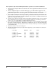
Chapter 6. Creating a Dedicated Map Table 6-1. Connections Name ATLAS 800 PLUS DS0s Name ATLAS 800 PLUS Port DS0s T1-A Controller T1 9-24 V.35 - A Quad V.35 N/A Data Slot 0 Port 1 RBS Off T1-B Controller T1 9-24 Data Slot 0/Port 2 RBS Off T1-C Quad T1/PRI 9-24 Data Slot 1/Port 1 RBS Off T1-A Controller T1 1-8 Voice Slot 0/Port 1 RBS On Slot 2/Port 1 V.35 - B Quad V.35 N/A Slot 2/Port 2 V.35 - C Quad V.
Chapter 6. Creating a Dedicated Map 2. Navigate to the Port index number of the second port and paste the configuration by pressing P. Repeat for the first port of the T1/PRI card located in Slot 1. 3. Navigate to the V.35 Port Configuration menu and repeat the configuration of the first port followed by copy and paste to the second and third ports. Implement the Map 1. Navigate to the Dedicated Map menu and select Create /Edit Map.
Chapter 6. Creating a Dedicated Map O. Set RBS to On for the Voice connections. P. (Optional) Using the Configuration submenu, set the trunk conditioning (Signaling and Data code) desired for T1 failure. Q. Repeat for the remaining Voice connections as in steps F through J above. A connection is not actually “made” (available) until you press Esc to move the cursor to the index number or move the cursor onto another connection line. Figure 6-3.
Creating a Dial Plan Chapter 7 OVERVIEW The ATLAS Dial Plan acts as the numbering plan for switched connections. This menu defines to ATLAS the phone numbers and features associated with dial-up ports. ATLAS supports Robbed Bit Signaling (RBS) T1 interfaces using DTMF dialing, Primary Rate ISDN (PRI) and Basic Rate ISDN (BRI).
Chapter 7. Creating a Dial Plan One ATLAS 800 PLUS (A) operates as the network while the other (B) “terminates” the network. In the example in Figure 7-2, ATLAS A is emulating the network and the PRI interface is a User Termination, while the PRI interface of ATLAS B is a Network Termination. Understanding the Dial Plan The Dial Plan menus are subdivided into three separate menus.
Chapter 7. Creating a Dial Plan Plan the Dial Plan 1. Determine the provisioning of the Network, and the attached equipment (video equipment and PBX).
Chapter 7. Creating a Dial Plan For our example there is one PRI port terminating the network (PRI A) and three BRIs (BRI A, B, C). (See Table 7-1 on page 7-4.) Table 7-1. Network Terminations NAME PORT OUTGOING ACCEPT # OUTGOING REJECT OTHER # PRI-A Controller T1 Blank - No called number will be rejected. PRI Type: National ISDN Slot 0, Port 1 $ - This port will forward any call to the network.
Chapter 7. Creating a Dial Plan For User Termination, there is one PRI, one RBS T1, and three BRIs (see Table 7-2 on page 7-5). Table 7-2. User Termination NAME PORT INCOMING ACCEPT # BRI D,E,F Octal BRI 888-1001 (D); Blank - No called 888-1002 (E); number will be 888-1003 (F) rejected. Slot 1, Port 4-5,6 OUTGOING REJECT # OTHER BRI type: 5ESS SPID # to match Video Equipment provisioning.
Chapter 7. Creating a Dial Plan 5. Select the Out (Outgoing) # Accept submenu. Enter $ in the number field. Leave all other selections set to default (Enabled). 6. Select the Out (Outgoing)# Reject submenu. Since no outgoing numbers need to be rejected at this port, no entry is required. 7. Select Interface Configuration (Ifce Config) submenu. Select the PRI switch type (National ISDN). Press ESC to back out of the connection to the index number column. 8. 9.
Chapter 7. Creating a Dial Plan After completion, the User Map should appear (see Figure 7-5). Figure 7-5. Completed User Map A connection is not actually “made” (available) until you press Esc to move the cursor to the index number or move the cursor onto another connection line.
Chapter 7.
Updating Firmware Chapter 8 FIRMWARE UPDATING To provide feature enhancements in the future, the ATLAS supports firmware updating by field personnel. Two transfer methods are available for use in updating any modules that contain Flash memory, including the system controller of the ATLAS. The first transfer method provided is via the ATLAS Chain-In port using XMODEM protocol. The second transfer method provided by ATLAS is via the ATLAS built-in Ethernet port using TFTP (Trivial File Transfer Protocol).
Chapter 8. Updating Firmware A Level 2 password is required for performing updates of any module within ATLAS. Please consult the ATLAS administrator if you do not know the password. 3. Select the System Utility menu. 4. Select Update Firmware. Figure 8-1 shows the Update Firmware menu. Figure 8-1. Update Firmware Menu Interface 5. Move to the Module Slot field. 6. Press Enter and select the appropriate module slot to update.
Chapter 8. Updating Firmware completed. The Restart at Specified Date and Time option allows you to select a date and time at which the ATLAS will automatically restart the module after the update process has completed. For modules which reside in expansion slots, the Restart at Specified Date and Time option is not available since the modules are unable to maintain normal operation during the update process. 10.
Chapter 8. Updating Firmware TFTP FIRMWARE UPDATING The ATLAS product supports updating of firmware to any module via the 10BaseT port using TFTP from a network server. The network server must be capable of supporting TFTP server requests from the TFTP Client within ATLAS. Update Firmware Using TFTP 1. Obtain the appropriate update file for the particular module from ADTRAN Technical Support.
Chapter 8. Updating Firmware Figure 8-2. Update Firmware Menu Interface Only Modules which are upgradable display as choices for the Module Type field when updating all modules of a type in the ATLAS. 9. Select TFTP for the Transfer Method. The ATLAS menu now displays two additional fields which must be entered for TFTP transfers. 10. In the field TFTP Server IP Address, enter the IP address of the network server that was recorded in Step 2.
Chapter 8. Updating Firmware 15. The Previous Update Status field indicates the results of the last firmware update for the particular slot chosen. If a firmware update has not been attempted for the particular slot, the Previous Update Status will display Has not been attempted. 16. After completing the configuration of all the above parameters, select the Begin Firmware Update field to activate the update process.
SNMP Management Chapter 9 UNDERSTANDING SNMP As local area network (LAN) environments became standardized over the past ten years, multi-vendor equipment grew with competition. It became necessary to manage the various vendor equipment from a single control console. Thus, SNMP emerged as the standard for managing commercial TCP/IP networks.
Chapter 9. SNMP Management TRAPS An SNMP trap is a message sent by a Network Device, such as the ATLAS, to report an operational anomaly or alarm condition. DEFINING A TRAP DESTINATION LIST For each trap event, a trap message will be sent to each member of the Trap Destination List. You can configure this list via Telnet session or VT100 menu.The ATLAS will support up to four trap destinations. By default, the destination list is empty.
Chapter 9. SNMP Management Table 9-2.
Chapter 9. SNMP Management Table 9-3. DS1 SNMP Traps Alarm Severity Description adATLAS800NoAlarm WARNING no alarms are present adATLAS800RxYellow MINOR the Far end is experiencing Red Alarm (a.k.a. Yellow Alarm) adATLAS800TxYellow WARNING the Near end is sending Loss Frame Indication (a.k.a. Yellow Alarm) adATLAS800RxAIS MINOR the Far end is sending Alarm Indication Signal (a.k.a. Blue Alarm) adATLAS800TxAIS WARNING the Near end is sending Alarm Indication Signal (a.k.a.
Chapter 9. SNMP Management DS1 ALERT TRAPS RFC1406 also defines a series of Current and Total Alert threshold values. You can enable the ATLAS to send an Alert Trap message to each member of the Trap Destination List when accumulated error statistics exceed these threshold values. Table 9-4 describes the Alert Traps supported by the ATLAS for events that have occurred in the last 15-minute interval. Table 9-4.
Chapter 9. SNMP Management Table 9-5 describes the Total Alert Traps, which describe events that have occurred in the last 24-hour interval. Table 9-5.
ADTRAN Utilities Chapter 10 UTILITIES DELIVERED WITH THE ATLAS_800PLUS ADTRAN delivers several software utilities on three diskettes with the ATLAS_800PLUS to make it easier for you to interface with the terminal menus and to transfer configuration files to and from TFTP servers. The diskettes also include the ATLAS_800PLUS MIB for use with SNMP (located in the MIB directory). The utilities all run on Microsoft Windows 3.1 or higher.
Chapter 10. ADTRAN Utilities Figure 10-1. Add New Dialog Box Port You can choose several options from the Port pulldown menu: • Telnet: establishes a Telnet session • Echo: provides a loopback for troubleshooting • Discard: bit bucket; discards data • Daytime: returns the time • Chargen: displays a unique character stream. Used for self-tests. Edit Entry The Edit Entry button allows you to change either the name or the IP address of each host (see Figure 10-2). Figure 10-2.
Chapter 10. ADTRAN Utilities Edit Menu Provides the Copy and Paste commands. Options Menu Colors Allows you to change the color of the background window, bold highlights, and text. Local Echo Echoes each character that you enter. AutoRepeat Repeats characters you select from the keyboard if you hold down the key. Capture Menu The Capture option copies the text on the current Telnet screen to the clipboard. You can open any word processor and paste the clipboard contents into the program.
Chapter 10. ADTRAN Utilities Figure 10-3. Port Settings Dialog Box Options Menu Connect Provides the options Transmit Wakeup and Transmit Refresh. Refresh Screen Redraws the screen. Colors These commands change the color of the background screen and text. Local Echo and Auto Repeat These options are the same as in the Telnet interface (see page 10-3 for details). Capture Menu The Capture option copies the text on the current VT-100 screen to the clipboard.
Chapter 10. ADTRAN Utilities Figure 10-4. TFTP Server Interface Only one configuration transfer session (upload or download) may be active at a time. The TCP/IP parameters are not saved or overwritten as part of an ATLAS 800 unit’s transferred configuration to allow sending identical configurations to multiple units. When you start this program, a port is automatically opened. Menu Options Server Menu Enable Enables the TFTP server.
Chapter 10. ADTRAN Utilities Clear Log Deletes the information stored in the Log field. Status Field This field displays general information about port and transfer status. This field is read-only. The unlabeled field in the center of the screen displays prompts about the status of active transfers, such as bytes transferred and received. Log Field This field displays a record of all of the events that occur during the time the TFTP server is enabled. Use the scroll bar to move up and down the list.
Chapter 10. ADTRAN Utilities Complete, and the Current Transfer Status field displays Idle. The file is now present on the TFTP server. (For the ADTRAN TFTP Server, it is stored in the installation directory or the directory you specified.) TFTP is not secure. No passwords are required for client access. Anyone can access files through the IP port on the server machine if they know the target file’s name.
Chapter 10. ADTRAN Utilities 8. 10-8 If the upload completes successfully, the unit reboots automatically and runs using the new configuration. If the upload fails, an error message is present in the Previous Transfer Status field. If the TFTP server cannot be contacted, the attempt takes approximately 20 seconds to timeout.
System Event Logging Appendix A This section describes the entries that may be logged by the system event log. Of particular importance is the log event’s Category – this is the minimum severity level that must be set in order that the event be logged. Use caution when changing Categories from their default levels. If too many sources have their Category values set too low, the number of messages being logged in a given period can be very large.
Appendix A. System Event Logging Table A-1. Source: System Event Category Console Log String Front Panel Display System Cold Start – generated 5 seconds after the completion of system initialization. Normal Cold Start COLD START SNMP Authentication Failure – generated if the ATLAS receives an SNMP request from an SNMP manager defined in the ATLAS SNMP Communities list but with a community name that does not match the community name defined in the SNMP Communities list.
Appendix A. System Event Logging Table A-2. Source: Switchboard Event Category Console Log String Front Panel Display Call rejected – no such number in dial plan Warning rejected: No such number n/a Call rejected – number is on outgoing reject list Normal rejected: Outgoing reject list n/a Call successfully routed Normal accepted: n/a Call rejected -- all end points busy Normal rejected: Busy n/a Table A-3.
Appendix A. System Event Logging Table A-3.
Appendix A. System Event Logging Table A-4.
Appendix A. System Event Logging Table A-4.
Appendix A. System Event Logging Table A-6.
Appendix A. System Event Logging Table A-6.
Appendix A. System Event Logging Table A-7.
Appendix A. System Event Logging Table A-7.
Appendix A. System Event Logging Each Cause Code IE log entry will end with a location designation. These designations are shown in Table A-8: Table A-8. Cause Code Log Entries Code Location U User LPN Private network serving the local user LN Public network serving the local user TN Transit network RLN Public network serving the remote user RPN Private network serving the remote user INTL International network INWK Network beyond internetworking point Table A-9.
Appendix A. System Event Logging Table A-11. Source: ISDN Information Elements Event Category ISDN Information Elements.
Troubleshooting Appendix B Table B-1. Troubleshooting SYMPTOM POSSIBLE CAUSES TROUBLESHOOTING TIPS Power-up Self-Test Fails Modules seated improperly, module failure Remove all modules and cycle power to the unit. If self-test still fails, call Technical Support and report the results. If the self-test now passes, reinsert modules one at a time, running the self test after installing each module. When an installed module causes the self-test to fail, note it and report results to tech support.
Appendix B. Troubleshooting Table B-1. Troubleshooting (Continued) SYMPTOM POSSIBLE CAUSES TROUBLESHOOTING TIPS Switched calls are not working Misconfiguration • Verify that the end point has proper call accept/ reject criteria. For RBS applications, check signaling bit status on the terminal interface for proper operation. • Verify that the end point is set up for correct signaling.
Appendix C Warranty and Technical Support Information WARRANTY AND CUSTOMER SERVICE ADTRAN will replace or repair this product within five years from the date of shipment if the product does not meet its published specifications or if it fails while in service. For detailed warranty, repair, and return information refer to the ADTRAN Equipment Warranty and Repair and Return Policy Procedure. Return Material Authorization (RMA) is required prior to returning equipment to ADTRAN.
Appendix C. Warranty and Technical Support Information issue an RMA number.
Index Symbols all # 5-30 Numerics 10-BaseT connection 2-6 pinout 2-6 port 2-2 status 5-10 15 minutes performance 5-27 24 hour performance 5-27 A abort 10-5 accept numbers 5-35, 5-38 access passwords 5-16 access rights 5-17 activate dedicated map 5-29 front panel 3-2 menu item 4-2 time 5-32 active alarm 4-9 add new (Telnet utility) 10-2 add password 5-17 address ADLP 5-12 ADLP address 5-12 ADTRAN utilities 10-1 ADTRAN data link layer protocol address 5-12 alarm blue 5-25 red 5-25 status 5-25 system 5-10
Index C called digits transferred 5-42, 5-47 caller ID number 5-49 cancel 3-1, 3-2 menu 4-2 cancel key 3-2 capture 10-3, 10-4 category 5-9 logging A-1 chain in 2-3 pinout 2-4 chain out 2-2, 2-4 pinout 2-5 chain port configure 5-13 framing errs 5-12 overrun errs 5-12 Rx bytes 5-11 signal leads 5-11 status menu 4-4 Tx bytes 5-11 chain port configuration 4-5 chain-in port 2-2 chain-out port 2-2 challenge # 4-8 clear performance data 5-26 selftest log 5-22 system event log 5-9 system LED 5-10 test pattern 5-28
Index description 1-4 data 56 kbps accept 5-38 56 kpbs reject 5-39 64 kbps accept 5-35, 5-38 reject 5-36, 5-39 data field 4-2 set 4-2 data tables 5-11 configuring 5-11 date 4-6 current 5-16 restart schedule 5-19 restart system 5-19 set 5-8 daylight savings 5-16 DCD chain port status 4-4 data carrier detect 5-11 D-chan 5-26 dedicate map create/edit 5-29 DS0 available 5-30 Dedicated 1-3 dedicated and switched connection maps description 1-3 dedicated map 5-28 activate 5-29 activate time 5-32 connections 6-1
Index end point configuration 5-41 enter dedicated map connections 5-29 enter key 3-1, 3-2 entry edit (Telnet utility) 10-2 erase alarm history 4-9 event log 5-9 selftest log 5-22 test results 4-8 error LED 3-4 errored seconds 5-26 errors inject 5-28 ES 5-26 ESF 2-5 ethernet 10BaseT connection 2-6 configuration config menu 4-5 connection 2-6 pinout 2-6 port 5-10, 5-13 configure 5-13 status status menu 4-4 ethernet configuration config menu 4-5 event description 5-9 log A-1 logging 5-16 severity 5-9 slot of
Index configuration from TFTP server 10-7 global parameters 5-39 global switch parameters 5-33 green CSU LED 3-4 green module status LED 3-4 ground start 5-48 grounding 2-1 grounding instructions 2-2 L I/F status 5-10 ID number 5-43, 5-47 ID presentation 5-43, 5-47 identification number 4-6 implement dedicated map 6-3 in#accept 5-37 incrementing fields 5-6 information controller 5-25 init modem 4-6 initialization 2-7 initialize modem 5-14 initialize modem 4-6 inject errors 5-28 insert dedicated map conne
Index map user map complete 7-7 map name 5-29 maps dedicated 5-28 nailed 5-28 max telnet session 5-13 memory installed 5-8 menu alarm 4-9 configuration 4-5 item activate 4-2 module 5-24 modules 5-23 path 5-4 session 10-1 status 4-4 submenu 5-25 system status 5-9 system utility 5-18 util 4-6 menu tree 4-3 menus dedicated maps 5-28 dial plan 5-33 modules 5-23 system config 5-12 system info 5-7 system utility 5-18 method signaling 5-44 MIB 10-1 modem initialize 5-14 modem initialization 4-6 modem initializati
Index switch type 5-51 user termination 5-51 offline 5-25 offline/no response 5-25 OK LED 3-4 online 5-24 online help 5-7 online LED 3-4 operating front panel 4-1 terminal menu 3-5, 5-1 VT 100 3-7 operating ATLAS 800 PLUS 3-5 operation 3-1 operation keys 3-3 option slot arrangement 2-7 numbering 2-7 option slots arrangement 2-7 out#rej 5-36, 5-39 outgoing caller ID 5-42, 5-47 outgoing number conversion 5-41 outgoing#accept 5-34 overrun errors 5-12 overview product 1-1 P packing list 2-1 panel rear 2-2 par
Index Quad T1/PRI interface configuration 5-41 network termination/PRI 5-41 network termination/RBS 5-43 user termination/PRI 5-46 user termination/RBS 5-48 R RBS 5-32 Quad T1/PRI 5-43, 5-48 RCV 5-26 real time clock 5-16 rear panel 2-2 reboot system 5-22 receive level 5-26 red alarm 5-25 red CSU LED 3-4 red module status LED 3-4 refresh screen 10-4 reject numbers 5-36, 5-39 remote access setup with dial plan 7-2 remote LB 5-28 remote loopback 5-28 repair C-1 reset password 4-8 response # 4-8 restart date
Index slot/port user termination 5-37 slt 5-23 SNMP 5-14 access 5-14 communities 5-14 IP address 5-15 privileges 5-15 software rev 4-7 solid green system LED 3-3 solid red system LED 3-3 sort to/from 5-29 source ID 5-34, 5-37, 5-43, 5-45, 5-47, 5-49 speech accept 5-35, 5-38 reject 5-36, 5-39 SPID list 5-50 Octal BRI 5-51 start ground 5-48 loop 5-48 start telnet session 3-6 startup mode mode startup 5-8 state module 5-24 status 10-BaseT 5-10 alarm 5-25 current configuration transfer 5-21 current firmware up
Index log out of a session 5-6 menu path 5-2, 5-4 moving around in 5-2 navigating 5-2 navigating with the keyboard keys 5-5 navigation help 5-4 operating 3-5 operation 5-1 paste items from clipboard 5-6 port status 5-4 refresh the screen 5-6 restore factory default settings 5-6 right pane 5-4 right pane notation 5-5 structure 5-1 Sys 5-4 system time 5-4 tool tip 5-4 window panes 5-2 terminal menu structure 5-1 termination network Octal BRI 5-50 user Octal BRI 5-51 terminations user 5-36 test 5-28 inject er
Index Octal BRI 5-51 Quad T1/PRI 5-46, 5-48 terminations 5-36 users logged into system, number of 5-18 using terminal menu 5-2 using front panel 3-5 util menu 4-6 utilities 10-1 utility Telnet 10-1 TFTP 10-1 TFTP server 10-4 VT 100 10-1, 10-3 utility menu 4-6 V video conferencing setup with dial plan 7-2 view event log 5-16 selftest log 5-22 view error log 5-9 view history 4-9 voice/SW56 5-44 VT 100 61200226L1-1A delivered utility 10-1, 10-3 operation 3-7 W WAN overbooking description 1-5 warnings view
Index Index-12 ATLAS 800 PLUS User Manual 61200226L1-1A
Product Support Information Presales Inquiries and Applications Support Please contact your local distributor, ADTRAN Applications Engineering, or ADTRAN Sales: Applications Engineering (800) 615-1176 Sales (800) 827-0807 Post-Sale Support Please contact your local distributor first. If your local distributor cannot help, please contact ADTRAN Technical Support and have the unit serial number available.