$7/$6ýåìí3/86 8VHUý0DQXDO 3DUWý1XPEHUýìëííëçè/ì 3DUWý1XPEHUýìëííëçç/ì 61200266L1-1A July 1999
TRADEMARKS Windows is a registered trademark of Microsoft Corporation. DMS 100 is a registered trademark of Northern Telecom. 5ESS is a registered trademark of AT&T. AT&T is a registered trademark. 901 Explorer Boulevard P.O. Box 140000 Huntsville, AL 35814-4000 (256) 963-8000 © 1999 ADTRAN, Inc. All Rights Reserved. Printed in U.S.A.
ADTRAN Year 2000 (Y2K) Readiness Disclosure ADTRAN has established a Year 2000 program to ensure that our products will correctly function in the new millennium. ADTRAN warrants that all products meet Year 2000 specifications regardless of model or revision. Information about ADTRAN's Year 2000 compliance program is available at the following: Product Matrix www.adtran.com/y2kfax.html E-mail year2000@adtran.
FCC regulations require that the following information be provided in this manual to the customer: 1. 2. 3. 4. 5. 6. 7. This equipment complies with Part 68 of the FCC rules. The required label is affixed to the bottom of the chassis. An FCC-compliant telephone cord with a modular plug is provided with this equipment. This equipment is designed to be connected to the telephone network or premises wiring using a compatible modular jack which is Part 68-compliant.
Affidavit Requirements for Connection to Digital Services • An affidavit is required to be given to the telephone company whenever digital terminal equipment without encoded analog content and billing protection is used to transmit digital signals containing encoded analog content which are intended for eventual conversion into voiceband analog signals and transmitted on the network.
rials and instructions provided by the manufacturer/grantee of the equipment used to encode analog signals; or ( ) C. An independent training course (e.g., trade school or technical institution) recognized by the manufacturer/grantee of the equipment used to encode analog signals; or ( ) D. In lieu of the preceding training requirements, the operator(s)/maintainer(s) is (are) under the control of a supervisor trained in accordance with _________ (circle one) above.
Canadian Equipment Limitations The Industry Canada Certification label identifies certified equipment. This certification means that the equipment meets certain telecommunications network protective, operational, and safety requirements. The Department does not guarantee the equipment will operate to the user's satisfaction. Before installing this equipment, users should ensure that it is permissible to be connected to the facilities of the local telecommunications company.
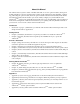
About this Manual The ATLAS 810PLUS system consists of the Base Unit and one or more option modules. (Each option module includes its own user manual which contains specific information about installing, configuring, and testing the option module; insert the option module manuals into this binder.
Notes, cautions, and warnings provide other significant information. They are easily identified, as shown below: Notes provide additional useful information. Cautions signify information that could prevent service interruptions. Warnings provide information that could prevent damage to the equipment or endangerment to human life.
x
Table of Contents List of Figures ..................................................................................................................................................xvii List of Tables..................................................................................................................................................... xix Chapter 1 Introduction.................................................................................................................................
Table of Contents Chapter 4 Using the Front Panel ................................................................................................................ 4-1 Overview ............................................................................................................................................................ 4-1 System LED ........................................................................................................................................................
Table of Contents Ethernet Port .............................................................................................................................................. 6-8 Chain Port .................................................................................................................................................. 6-9 SNMP ..........................................................................................................................................................
Table of Contents Port/PEP .................................................................................................................................................... 9-3 Sig ................................................................................................................................................................ 9-3 Out#Accept ................................................................................................................................................
Table of Contents Network Manager ............................................................................................................................ 11-1 Agent .................................................................................................................................................. 11-1 MIB ..................................................................................................................................................... 11-1 SNMP Traps....................
Table of Contents Refresh Screen ......................................................................................................................................... 12-9 Connect ..................................................................................................................................................... 12-9 Colors ........................................................................................................................................................
List of Figures Figure 1-1. Point-to-Point Circuit. . . . . . . . . . . . . . . . . . . . . . . . . . . . . . . . . . . . . . . . . . . . . . . . . . . . . . . . . 1-2 Figure 1-2. Frame Relay Circuit . . . . . . . . . . . . . . . . . . . . . . . . . . . . . . . . . . . . . . . . . . . . . . . . . . . . . . . . . . 1-3 Figure 1-3. Digital Access Cross-Connect System (DACS) . . . . . . . . . . . . . . . . . . . . . . . . . . . . . . . . . . . 1-4 Figure 1-4. T1 Bandwidth Management . . . . . . . . . . . . . .
List of Figures Figure 12-5. TFTP Server Interface Menu Tree . . . . . . . . . . . . . . . . . . . . . . . . . . . . . . . . . . . . . . . . . . . . 12-10 Figure 12-6. TFTP Server Interface . . . . . . . . . . . . . . . . . . . . . . . . . . . . . . . . . . . . . . . . . . . . . . . . . . . . . .
List of Tables Table 2-1. Control/Chain In Pinout . . . . . . . . . . . . . . . . . . . . . . . . . . . . . . . . . . . . . . . . . . . . . . . . . . . . . 2-5 Table 2-2. Control/Chain Out Pinout . . . . . . . . . . . . . . . . . . . . . . . . . . . . . . . . . . . . . . . . . . . . . . . . . . . . 2-6 Table 2-3. Ethernet 10BaseT Pinout . . . . . . . . . . . . . . . . . . . . . . . . . . . . . . . . . . . . . . . . . . . . . . . . . . . . . 2-6 Table 2-4. Alarm Relay Connector Pinout . . . . . . . .
List of Tables xx ATLAS 810PLUS User Manual 61200266L1-1
Chapter 1 Introduction PRODUCT OVERVIEW The ATLAS 810PLUS is a modular, highly scalable platform that provides robust solutions for the wide area communication needs of medium-to-large corporations and network access providers. ATLAS is an Integrated Access System with the most extensive support of dedicated bandwidth management and access switching in the industry. The ATLAS 810PLUS is a high performance version of the ATLAS 800PLUS.
Chapter 1. Introduction The ATLAS modules include the following: • HDLC Module • Quad T1/PRI Module • Octal Basic Rate ISDN Module • T3 Module • Async-232 Module • Modem-16 Module Frame Relay Frame relay is a packet-switched service that allows efficient transfer of bursty traffic in a WAN environment. It offers lower-cost data transfer when compared to typical point-to-point applications.
Chapter 1. Introduction Router Frac T1 PBX PBX ATLAS 810PLUS T1 Router Frame Relay DDS PBX Router Router DDS PBX Figure 1-2. Frame Relay Circuit The Frame Relay/Router upgrade option adds the capability for the ATLAS series of Integrated Access Devices to act as a voice/data FRAD, a frame relay switch, and an IP router in addition to the current available bandwidth manager and switch applications.
Chapter 1. Introduction Flexible Network Management and Maintainability Several network management methods are available for the ATLAS 810PLUS, including SNMP support. VT 100 and Telnet are also offered, providing detailed system configuration through an easy-to-use menu system. The terminal interface is secured by six levels of password protection with varying degrees of management privileges.
Chapter 1. Introduction T1 Bandwidth Manager As a T1 Bandwidth Manager, ATLAS 810PLUS combines the functions of a T1 CSU/DSU, an intelligent channel bank, a T1 Multiplexer, and DACS into a single platform. The Bandwidth Manager supports a wide range of data applications including T1 “drop and insert,” channel grooming, and wide area data transport. ATLAS is ideal for point-to-point configurations or access to public networks.
Chapter 1. Introduction ATLAS 810PLUS Express 3000 Figure 1-5.
Chapter 1. Introduction Dedicated Connection Maps • Up to five connection maps • Time of day/day of week configurable • Preserves signaling through cross-connect • No effect on nonconfigured channels Switched Connection Maps • Inbound and outbound call filtering and blocking Testing • Local and remote: payload/line, V.
Chapter 1.
Chapter 2 Installation INSPECT THE ADTRAN SHIPMENT Before installing the ATLAS 810PLUS, carefully inspect the ATLAS 810PLUS Base Unit for shipping damage. If you suspect damage, file a claim immediately with the carrier and then contact ADTRAN Technical Support (see Warranty and Technical Support Information on page C-1). If possible, keep the original shipping container for returning the ATLAS 810PLUS for repair or for verification of damage during shipment.
Chapter 2. Installation AC Powered Unit The AC powered ATLAS 810PLUS (P/N 1200265L1) comes equipped with a detachable 8-foot power cord with a 3-prong plug for connecting to a grounded power receptacle. Power to the ATLAS 810PLUS must be from a grounded 115 VAC, 60 Hz or 220 VAC, 50-60 Hz source. DC Powered Unit The DC powered ATLAS 810PLUS (P/N 1200266L1) comes equipped with a terminal block on the rear of the unit.
Chapter 2. Installation A supplementary equipment grounding conductor shall be installed between the product or system and ground that is in addition to the equipment grounding conductor in the power supply cord. The supplementary equipment grounding conductor shall not be smaller in size than the ungrounded branch-circuit supply conductors.
Chapter 2. Installation Control/Chain Out NTWK1 Connects to Chain In of another unit RJ-48C Connection Port Control/ Chain In Interface of Chain In 10 Base T MON (Monitor) NTWK2 RJ-48C Connection Port Bantam test jack RJ-48C Connection Port Power Switch Alarm Relay Connection CAUTION: MAINTENANCE TO BE PERFORMED BY TRAINED SERVICE PERSONNEL ONLY CAUTION: FOR CONTINUTED PROTECTION AGAINST RISK OF FIRE, REPLACE ONLY WITH SAME TYPE AND RATING OF FUSE.
Chapter 2. Installation Connection The Control/Chain In connection follows with the pinout shown in Table 2-1. Connector type RJ-48C Part number AMP# 555164-2 Table 2-1.
Chapter 2. Installation Table 2-2. Control/Chain Out Pinout PIN NAME DESCRIPTION 1 GND 2 UNUSED — 3 TX DATA 4 UNUSED — 5 RX DATA 6,7,8 Ground - connected to unit chassis. Connects to GND of next unit (pin1). Data transmitted to chained units by the ATLAS 810PLUS. Connects to RX DATA of the next unit (Chain In pin 3). Data received from chained units by the ATLAS 810PLUS. Connects to TX DATA of the next unit (Chain In pin 5).
Chapter 2. Installation Alarm Relay Connection This connection alerts the user when a selected alarm condition exists. The four-pin, removable terminal block connects with external wiring. To make the appropriate connections, remove the block, connect wiring as needed, and return the terminal block to the connector socket. Clear the alarm condition by pressing the Alarm Cut-Off (ACO) switch located on the font panel of the ATLAS 810PLUS.
Chapter 2. Installation Network Connection The two eight-pin modular jacks labeled NTWK 1 and NTWK 2 provide the network connection. The two Network Interface (NI) ports comply with the applicable ANSI and AT&T® standards.
Chapter 2. Installation Option Slots 6/27ýì 6/27ýè 6/27ýë 6/27ýç 6/27ýê 6/27ýæ 6/27ýé 6/27ýå POWER SUPPLY Figure 2-3 shows the option slot numbering designation, as viewed from the rear of the ATLAS 810PLUS. All slots are functionally identical except slots 7 and 8, which can also accommodate an optional power supply for redundancy. Figure 2-3.
Chapter 2.
Chapter 3 Operation OVERVIEW To fully operate the ATLAS 810PLUS, you must connect to the terminal menu using VT-100 terminal emulation or a Telnet session. For limited configuration control, use T-Watch PRO. The following sections provide an overview of these methods of operating the ATLAS 810 PLUS. USING THE TERMINAL MENU The terminal menu provides the primary means of monitoring and configuring the ATLAS 810PLUS.
Chapter 3. Operation Instructions for Setting Up an ATLAS 810PLUS for VT-100 Terminal Mode Step 1 2 Action Set the baud rate on the VT-100 terminal to 9600 baud (8/N/1). Use the ADTRAN-provided VT-100 terminal adapter to connect the COM port of a VT-100 compatible terminal, or equivalent, to the eight-pin modular jack labeled CONTROL/CHAIN IN on the rear panel or labeled CRAFT on the front panel. This connection provides both local and remote configuration.
Chapter 3. Operation USING TELNET To connect to the ATLAS 810PLUS via Telnet, you must define the IP address, set the subnet mask, and, typically, set the default gateway IP address. You must define the IP address before attempting to connect via Telnet. See Using VT-100 Terminal Emulation on page 3-1 for details on defining the IP address. You will need a default gateway if the LAN contains multiple segments. Contact your LAN administrator for the appropriate address.
Chapter 3.
Chapter 4 Using the Front Panel OVERVIEW The front panel contains the System LED, the Alarm Cut-off (ACO) switch, and the CRAFT port. The front panel also contains controller and module status LEDs that provide visual information about the ATLAS 810PLUS Base Unit and any option module that may be installed. Figure 4-1 identifies the System LED, the ACO switch, the CRAFT port, and the LEDs.
Chapter 4. Using the Front Panel CRAFT PORT Use the CRAFT port to configure the system via an EIA-232 connection. The CRAFT port provides the same functions and operations as the Control In port located on the rear panel of the ATLAS 810PLUS. Table 4-1 gives the CRAFT port pinout (see also CRAFT Port on page 4-3 in Table 4-2). Table 4-1.
Chapter 4. Using the Front Panel Table 4-2. ATLAS 810PLUS Front Panel Description Feature Controller Status LEDs Description Indicates the status of both network interfaces. (See also Table 4-3 on page 4-4.) OK Indicates that both integral network interfaces are operating correctly. Test Indicates that one of the network interfaces is in a test mode. Error Blinks to indicate the occurrence of error events. Alarm Indicates an alarm condition on one of the network interfaces.
Chapter 4. Using the Front Panel Table 4-3. LED Descriptions For these LEDs... This color light... Indicates that... System Green (solid) No diagnosed system faults were found. Green (fast blink) Flash download is in progress. Yellow (solid) A fault was diagnosed, but the condition no longer exists. The condition will be recorded in the system log. Red (solid) An error condition with either the power supply or the temperature is present.
Chapter 5 Navigating the Terminal Menu TERMINAL MENU WINDOW The ATLAS 810PLUS uses a multilevel menu structure that contains both menu items and data fields. All menu items and data fields display in the terminal menu window, through which you have complete control of the ATLAS 810PLUS (see Figure 5-1). Menu Path Right Pane Left Pane Port Status Navigation Help Sys Tool Tip Extended Help System Time Figure 5-1.
Chapter 5. Navigating the Terminal Menu Window Panes When you first start a terminal menu session, the terminal menu window is divided into left and right panes. The left pane shows the list of available submenus, while the right pane shows the contents of the currently selected submenu. Submenus that display horizontally can also be viewed vertically: move your cursor to an index number and press return.
Chapter 5. Navigating the Terminal Menu Additional Terminal Menu Window Features The following features are located across the bottom of the window: Sys Describes the status of the ATLAS base unit. Tool Tip Provides a brief description of the currently selected (highlighted) field. Port Status Displays status information, such as OK, WARN (warning), or ALRM (alarm), about ports 1—8. Extended Help (Ctrl-A) Displays information about selected commands.
Chapter 5. Navigating the Terminal Menu To do this... Press this key... Move between the left and right panes. Tab Arrows Move to the top of a screen. A Move to the bottom of a screen. Z Ascend one menu level. Backspace Session Management Keystrokes To do this... Press this... Log out of a session. Ctrl-L Invalidate the password entry and return to the login screen. Ctrl-S Refresh the screen. To save time, only the portion of the screen that has changed is refreshed.
Chapter 5. Navigating the Terminal Menu Configuration Keystrokes To do this... Press this key... Restore factory default settings. This setting restores the factory defaults based on the location of the cursor. If the cursor is on a module line (in the Modules menu), then only the selected module is updated to factory defaults. F Copy selected items to the clipboard.
Chapter 5.
Chapter 6 Terminal Menu and System Control SELECTING THE APPROPRIATE MENU The terminal menu is the access point to all other operations. Each terminal menu item has several functions and submenus that identify and provide access to specific operations and parameters. Use the chart below to help you select the appropriate terminal menu. To do this... Go to this menu... For more info... Review and monitor general system information for the ATLAS 810PLUS. System Info See page 6-2.
Chapter 6. Terminal Menu and System Control Table 6-1. Password Security Levels Security Level Description 5 Read-only permission for all menu items—minimum rights. 4 Read permission for all menu items and permission to use test commands. 3 Access to all commands except passwords, flash download, authentication methods, and interface configurations. 2 Access to all commands except passwords, flash download, and authentication methods. 1 Access to all commands except passwords.
Chapter 6. Terminal Menu and System Control » System Name Security level: 3; Read security: 5 Provides a user-configurable text string for the name of the ATLAS 810PLUS. This name can help you distinguish between different installations. You can enter up to 40 alpha-numeric characters in this field, including spaces and special characters (such as an underbar). This name also displays on the LCD Front Panel.
Chapter 6. Terminal Menu and System Control » Boot ROM Rev > SYSTEM STATUS Read security: 5 Displays the boot ROM revision. The System Status menu provides information on the status of the unit. Figure 6-2 shows the submenu functions available in the System Status menu. Figure 6-2. System Status Menu » Event Log Read security: 5 Displays the last 350 warning or failure messages sent—including the day, date, and priority of the message. The most recent messages display at the top of the list.
Chapter 6. Terminal Menu and System Control » Clear System Event Log Write security: 3; Read security: 5 Clears the event log. When you select the command, the following prompt displays: This will clear the entire event log. Confirm (y/n). Select Y to clear the log or N to exit the command. If you clear the event log, you cannot retrieve the data. » Ethernet Port Read security: 5 Displays status information about the Ethernet port. An asterisk (*) indicates activity for the item.
Chapter 6. Terminal Menu and System Control » Resource Usage Write security: 4; Read security: 5 Indicates resource use (analog modems; digital modems; voice compression). »» Data Tables Tracks resource usage for dynamic resources throughout the system and presents the information in a table format. Resource Type Displays the system resources list. Current Shows the number of resources available (not in use) and the total number of resources.
Chapter 6. Terminal Menu and System Control » Chain Port Rx Bytes Read security: 5 Displays the number of received data bytes. » Chain Port Overrun Errs Read security: 5 Displays the number of overrun errors. » Chain Port Framing Errs Read security: 5 Displays the number of received framing errors. » Clear Chain Port Countrs Clears all chain port counters. Press Y to activate command. > SYSTEM CONFIG The System Config menu allows you to set up the ATLAS operational configuration.
Chapter 6. Terminal Menu and System Control » ADLP Address Write security: 2; Read security: 5 Shows the system ADTRAN Data Link Layer Protocol (ADLP) address for connecting remote devices to management software (such as T-Watch PRO). The allowable range is between 2 and 65520. Enter a value not used by any of the TSU units controlled by the management software.
Chapter 6. Terminal Menu and System Control » Chain Port Write security: 2; Read security: 5 Accepts input for configuring the Chain In port. »» Port Name Write security: 2; Read security: 5 Defines the name of the chain port. Type in an alpha-numeric name up to 57 characters long. The name can include spaces and special characters. »» Port Type Write security: 2; Read security: 5 Specifies whether you use Direct or Dial mode.
Chapter 6. Terminal Menu and System Control »» Trap Transmission Write security: 3; Read security: 5 Enables and disables SNMP trap transmission. »» Authen Trap Transmission Write security: 3; Read security: 5 Enables and disables the authentication failure trap. »» Traps Destination Write security: 3; Read security: 5 Defines the destination for SNMP traps as follows: IP Address Identifies the IP address to which the network manager sends traps.
Chapter 6. Terminal Menu and System Control Current CSS Thrsh The DS1 performance monitor Threshold Value for the Current 15 minute Controlled Slip Seconds (SES) parameter. The default value is 1 for an approximate BER level of 10E-5. Current PCV Thrsh (D4) The DS1 performance monitor Threshold Value for the Current 15 minute Path Code Violation (PCV) parameter, when the Line Type is Super Frame (AT&T D4 format) DS1. The default value is 72 Framing errors for an approximate BER level of 10E-5.
Chapter 6. Terminal Menu and System Control (ESF) DS1. The default value is 132,960 CRC errors for an approximate BER level of 10E-5. Total LES Thrsh The DS1 performance monitor Threshold Value for the Total Line Errored Seconds (LES) parameter. The default value is 648 for an approximate BER level of 10E-5. Total LCV Thrsh The DS1 performance monitor Threshold Value for the Current 15 minute Line Code Violations (LCV) parameter. The default value is 133,400 for an approximate BER level of 10E-5.
Chapter 6. Terminal Menu and System Control » Access Passwords Write security: 0; Read security: 5 Provides a way to edit passwords and, also, to add new users and passwords. All menu items are protected by passwords of varying security levels. By assigning different passwords to different security levels, the ATLAS system administrator can control which users can change various menu items. You can assign multiple passwords at the same access level.
Chapter 6. Terminal Menu and System Control Instructions for Changing Passwords Step Action 1 Select the Password field—a new Password field displays. 2 Type the new password in the Enter field. 3 Type the new password again in the Confirm field. The password can contain up to 12 alphanumeric characters. You can also use spaces and special characters in the password. »» Access Rights Write security: 0; Read security: 5 Defines the password level for the corresponding label.
Chapter 6. Terminal Menu and System Control » BONDING Config »» TXINIT Timer (sec) This option specifies the length of time the originating endpoint attempts to detect the BONDING negotiation pattern from the answering endpoint before deciding the BONDING call has failed. »» TXFA Timer (sec) This option specifies the length of time both endpoints attempt to detect the BONDING frame pattern when a call is connected before deciding the BONDING call has failed.
Chapter 6. Terminal Menu and System Control > SYSTEM UTILITY Use the System Utility menu to view and set the system parameters shown in Figure 6-4. Figure 6-4. System Utility Menu » Update Firmware Write security: 1; Read security: 5 Updates firmware when ATLAS 810PLUS enhancements are released. Two transfer methods are available for use in updating any modules that contain Flash memory—including the ATLAS system controller.
Chapter 6. Terminal Menu and System Control »» Module Type Write security: 1; Read security: 5 Reflects the module type selected in Module Slot. This is normally a readonly field; however, if you selected All Modules of a Type, you must select a particular module type to update all modules of that type. The selections only include upgradable modules.
Chapter 6. Terminal Menu and System Control »» Current Update Status Read security: 5 Indicates progress or problems encountered during the current update process. The field displays Idle if no update is in progress or when the update is successfully completed. At the end of a successful update, the contents of this field are copied into Previous Update Status.
Chapter 6. Terminal Menu and System Control To support these transfers, ADTRAN delivers a TFTP program with ATLAS 810PLUS called TFTP Server. You can configure any PC running Microsoft Windows with this software, and store a configuration file. See TFTP Server on page 12-10 for details on how to use TFTP Server. Before using Config Transfer, the ATLAS 810PLUS should have a valid IP address, subnet mask, and default gateway (if required), and should be connected to an Ethernet network.
Chapter 6. Terminal Menu and System Control »» Save Config Remotely Write security: 3; Read security: 5 Saves the configuration file specified in TFTP Server Filename to the server identified in TFTP Server IP Address. To start this command, enter Y to begin or enter N to cancel. Before using this command, you must have identified a valid TFTP Server in TFTP Server IP Address. » System Utilization Write security: 0; Read security: 0 Displays statistics related to the ATLAS internal operating system.
Chapter 6. Terminal Menu and System Control »» View Selftest Log Read security: 5 Displays time-stamped log of the tests conducted and the Pass/Fail results. Self-tests verify data integrity and processor control to each port. Each port is looped back and a data pattern is sent and tested. The result of the self-test on each installed port is listed with Pass/Fail results. A typical test log is shown in Figure 6-5 on page 6-21. The log includes the following additional fields.
Chapter 6. Terminal Menu and System Control »» Clear Self-test Log Write security: 3; Read security: 5 Clears the self-test log. » Ping Write security: 5; Read security: 5 Allows you to send pings (ICMP requests) to devices accessible via the network. Only one ping session can be active at a time. »» IP Address Write security: 5; Read security: 5 Specifies the IP address to ping. »» Count Write security: 5; Read security: 5 Specifies the number of pings to send.
Chapter 6. Terminal Menu and System Control »» Start/Stop Write security: 5; Read security: 5 If the ping client is currently idle, this menu sends pings to the specified address. If the ping client is active, the menu stops sending pings. » Reboot System Write security: 2; Read security: 5 Reboots the ATLAS 810PLUS. When you select this command, the following message displays: **WARNING ** This will reboot the entire system!ýPress y to reboot the system, or n to exit the command.
Chapter 6.
Chapter 7 Modules Terminal Menu To help you follow the terminal menu hierarchy, the following notations are used: > MENUS » Submenus »» Sub-submenus Submenu Options > MODULES Write security:3; Read security:5 The Modules menu provides options that allow you to configure and control the installed option modules as well as the controller T1/PRI ports. Figure 7-1 shows the Modules menu. Figure 7-1. Modules Menu The controller board (slot 0) has two T1/PRI interface ports.
Chapter 7. Modules Terminal Menu » Slt Write security:3; Read security:5 Identifies the slot number. Slot 0 refers to the ATLAS 810PLUS Base Unit. » Type Write security:3; Read security:5 Displays the type of module actually installed in the slot or the type of module you plan to install in the slot. The ATLAS 810PLUS automatically detects the type of module installed in each slot, and the Type field automatically defaults to the installed module type.
Chapter 7. Modules Terminal Menu » State Read security:5 Displays whether the module is online of offline. Even though a module is physically installed, it must be marked Online for it to be considered an available resource. This parameter allows an installed module to be marked Offline, which may be useful in system troubleshooting. If you choose Offline, the module will not be in alarm condition, but will display Offline.
Chapter 7. Modules Terminal Menu Modules Menu (Quad T1/PRI) This section provides detailed information on the Modules/Menu submenus. Menu provides access to commands that allow you to review the status of various options, change the configuration for general parameters, and initiate tests. This section only describes the menu options for the Quad T1/ PRI controller port (the ATLAS 810 PLUS Base Unit). For details on menu options for individual modules, refer to the appropriate module manuals.
Chapter 7. Modules Terminal Menu »» DS0 Status »» DS0 Alarms Read security:5 Indicates usage on a DS0 basis for each port as follows. * Inactive A Active call on this DS0 D Active D channel DS0 M Maintenance DS0 N Dedicated DS0 O Off hook detected R Ringing detected Indicates DS0 alarm as follows: - No alarm DS0 D D channel alarm (ISDN) F Frame alarm (Packet) T TBOP alarm (Packet) »» Sig Status Read security:5 Indicates signaling of all 24 DS0s.
Chapter 7. Modules Terminal Menu LCV Line Code Violations. PCV Path Code Violations. LES Line Errored Seconds. »» Performance: 15 Min Write security:3; Read security:5 In the Performance 15 min. menu, the performance data for the previous 15 minute window is stored. Refer to Performance: Curr on page 7-5 for a detailed description. »» Performance: 24 Hr. Write security:3; Read security:5 In the Performance 24 hr. menu, the performance data for the previous 24 hour window is stored.
Chapter 7. Modules Terminal Menu »» Test Initiates different types of tests and displays test results. These Test commands temporarily disrupt service. Prt Identifies the port number. Loc LB Read security:5 (Local Loopback) Causes loopback on near-end port. Remote LB Line Metallic loopback Payld Payload loopback framing and clocking are regenerated. Write security:4; Read security:5 (Remote Loopback) Sends a loopback code to a remote CSU. ANSI FDL Line Requires ESF mode.
Chapter 7.
Chapter 8 Dedicated Maps Terminal Menu OVERVIEW The Dedicated Maps menu assigns dedicated connections between any two ports in the ATLAS 810PLUS Base Unit. This chapter describes the Dedicated Maps menu items (see Figure 8-1). In addition, step-by-step instructions are provided for setting up a sample dedicated map (see Creating A Dedicated Map on page 8-6).
Chapter 8. Dedicated Maps Terminal Menu > ACTIVATE MAP Write security:3; Read security:5 Activates a dedicated map—automatically or manually. You can have up to five different dedicated maps, each with an optionally specified name. » Auto Automatically activates a particular dedicated map at the time and day specified in Activate Time (see Activate Time on page 8-5). » Maps 1—5 Lets you manually activate a specific dedicated map.
Chapter 8. Dedicated Maps Terminal Menu »» # (Index Number) Displays the number of the dedicated map connection. If you press I in this field, ATLAS 810PLUS adds another dedicated map connection, numbered consecutively. »» FROM Slt Write security:3; Read security:5 (From Slot) Specifies the slot to use for the FROM connection. When you select this option, a list of all of the slots and the modules installed in the slots displays. Pick the appropriate slot and press Enter.
Chapter 8. Dedicated Maps Terminal Menu Trunk Conditioning Write security: 3; Read security: 5 Sets known values in the signaling bits and the data field for outgoing DS0s which are cross-connected to a T1 port experiencing alarms. The trunk conditioning process consists of a 2.5-second transmission (indicating call termination), followed by a continuous transmission signaling the final condition as chosen by the user. Trunk conditioning only applies to RBS T1s in the dedicated map.
Chapter 8. Dedicated Maps Terminal Menu »» TO Slot Write security: 3; Read security: 5 Specifies the slot to use for the second end of a connection. Select this option, and a list of all of the slots and the modules installed in the slots displays. Pick the appropriate slot. »» Port Write security: 3; Read security: 5 Selects the port used for the second connection. When you select this option, a list of all the slots and available modules displays. Select the appropriate slot.
Chapter 8. Dedicated Maps Terminal Menu For this example, assume voice traffic is received on T1-A, and T1-B is groomed onto T1-C to the PBX (see Figure 8-2). If T1-A fails, the DS0s which were cross-connected to T1-C will receive trunk conditioning. PBX ATLAS 800 T1-A T1-B T1-C Figure 8-2. Trunk Conditioning Example 2 Creating A Dedicated Map A dedicated map defines connections for dedicated bandwidth between ports, and grooms and cross-connects bandwidth between T1 ports.
Chapter 8. Dedicated Maps Terminal Menu by-step procedures for creating a sample dedicated map based on the connections and ports given in Table 8-1. Table 8-1. Connections and Ports Name ATLAS 810PLUS Port DS0s Name ATLAS 810PLUS Port DS0s T1: Data A Controller T1 Slot 0 Port 1 9-24 RBS Off V.35 - A Quad V.35 Slot 2/Port 1 N/A T1: Data B Controller T1 Slot 0/Port 2 9-24 RBS Off V.35 - B Quad V.35 Slot 2/Port 2 N/A T1: Data C Quad T1/PRI Slot 1/Port 1 9-24 RBS Off V.35 - C Quad V.
Chapter 8. Dedicated Maps Terminal Menu Figure 8-4. Slot 0 Module Configuration Menu Defining the Connections for Example 2 Begin by navigating to Dedicated Maps/Create/Edit Maps and naming your map. Navigate to Dedicated Maps/Connects. The Connects submenu defines the connections necessary to route the required bandwidth. Refer to Table 8-1 on page 8-7 to define each of the necessary connections. For this procedure, first define the data connections, and then define the voice connections.
Chapter 8. Dedicated Maps Terminal Menu Instructions for Defining Data Connections (Continued) Step Action 6c Paste this information onto a new connection line by positioning the cursor over the index numbers of the new connections, and pressing P. 7 Modify these connection lines to complete the connections for data. Instructions for Defining Voice Connections Step Action 1 Select the FROM Slot and Port for the first voice connection (i.e., Slot 0/Port 1 for T1-A Voice).
Chapter 8. Dedicated Maps Terminal Menu Figure 8-5.
Chapter 9 Dial Plan Terminal Menu OVERVIEW The Dial Plan submenus (see Figure 9-1) set global ATLAS switch parameters as well as individual parameters for each ATLAS port handling a switched call. The individual ports are separated into two port types: network and user. Network ports terminate a connection from the Network. User ports terminate incoming calls and, in turn may be connected to user , equipment.
Chapter 9. Dial Plan Terminal Menu Network Term # # Slot/Svc Src ID Port/PEP Accept Number Sig Search Out # Accept Data 64K Data 56K Audio Speech Treat Call As # Reject Number Out#Rej Data 64K Data 56K Audio Speech Ifce Config These submenus vary depending on the Slot/Svc and SIG.
Chapter 9. Dial Plan Terminal Menu > NETWORK TERM This menu allows the user to define option parameters for ports which terminate a connection from the Network (PSTN). In applications where two ATLAS units are used in a point-to-point configuration, a port in the ATLAS at one end would act as the Network (User termination), while the ATLAS at the opposite end would be terminating a “Network” connection.
Chapter 9. Dial Plan Terminal Menu »» Accept Number Designates which numbers this endpoint passes on toward the Network (PSTN). The accept list may consist of multiple entries. The numbers are defined using the following “wild cards”: X = Any single digit N = Any single digit 2—9 $ = Any number of digits of any value 9 = This specific number [1,2,3...] = A single digit in this group For example, 1-800-$ only permits toll free long distance calls to 1-800.
Chapter 9. Dial Plan Terminal Menu » Out#Rej Write security: 3; Read security: 5 Defines the parameters for the outgoing calls that ATLAS will not send to the Network. »» Reject Number Identifies which numbers this endpoint will not pass on toward the Network (PSTN). The reject list may consist of multiple entries. The reject list may be used to more easily specify the call filtering desired. The “wild cards” are identical as in Outgoing Call Accept.
Chapter 9. Dial Plan Terminal Menu » Sig Write security: 3; Read security: 5 (User Selection - RBS; PRI) Defines the type of signaling being used for this connection (endpoint). Select RBS for a T1 using Robbed Bit Signaling, NFAS for a Primary Rate ISDN interface using Non-Facility Associated Signaling, and PRI for a Primary Rate ISDN interface. This selection is only necessary if a T1/PRI is selected as the Slot/Port type.
Chapter 9. Dial Plan Terminal Menu »» Search Primary Search Write Security: 3; Read Security: 5 Defines to ATLAS the order in which to search for an accept number. The Search parameter instructs ATLAS which order to search for an accept number match. Normally all searches are set to primary. The secondary search selection would be used to force ATLAS to only accept a call at this endpoint if all primary endpoints were unavailable.
Chapter 9. Dial Plan Terminal Menu »» Data 56K, Data 64K, Audio, Speech Rejects outgoing calls based on call type. For example, setting the reject number to $, Digital 56/64 to enabled, and Audio and Speech to disabled, rejects all digital calls while not rejecting analog calls. This list may remain blank if the Accept List meets desired filtering. The Call Reject list takes precedence over the Call Accept list. » Ifce Config Sets configuration parameters for the endpoint.
Chapter 9. Dial Plan Terminal Menu » Number Type Templates Write security: 1; Read security: 5 Sets call type patterns. ISDN interfaces require that a number type be sent over the D channel when a call is sent or received. A normal RBS trunk does not send a type designator, but uses prefixes instead. For example, “1 +” prefix is a national long distance call type while a “011 +” prefix is an international long distance call type.
Chapter 9. Dial Plan Terminal Menu INTERFACE CONFIGURATIONS This section describes Dial Plan Network Termination and User Termination configuration settings for the following modules. Quad T1/PRI Module (Network Termination/PRI). . . . . . . . . . . . . . . . . page 9-10 Quad T1/PRI Module (Network Termination/NFAS). . . . . . . . . . . . . . . page 9-12 Quad T1/PRI Module (Network Termination/RBS) . . . . . . . . . . . . . . . . page 9-13 Quad T1/PRI Module (User Termination/PRI) . . . . . . . . . . . . .
Chapter 9. Dial Plan Terminal Menu »» Outgoing Number Conversion As dialed Write Security: 3 Read Security: 5 Defines the rules for converting as-dialed numbers into ISDN number type and plan. Send digits provided as unknown number type. ISDN - National pref Convert to ISDN type, using the 10-digit national form if possible. ISDN - Subscriber pref Convert to ISDN type, using the 7-digit subscriber form if possible.
Chapter 9. Dial Plan Terminal Menu »» Outgoing Caller ID Write Security: 3 Read Security: 5 Inserts a called ID based on the following selections: Send as provided ATLAS forwards whatever ID it receives (including None). Substitute if not present ATLAS inserts a User-defined ID value if no value is received. ID Presentation Sends to the Network control information for the presentation of Caller ID (Presentation Allowed; Presentation Restricted; Number Not Available).
Chapter 9. Dial Plan Terminal Menu lowing configuration menu is available (in addition to the standard Network Termination/PRI configuration menus and options): » Secondary Interfaces Write security: 3; Read security: 5 Defines the additional PRI interfaces controlled by the D-channel on this endpoint. » Slot, Port Write security: 3; Read security: 5 Defines the slot and port in which the additional interface terminates.
Chapter 9. Dial Plan Terminal Menu »» DS0s Available Read security: 5 Indicates which DS0s of the T1 have been defined in this switched endpoint (indicated by “! “), in another switched endpoint (indicated by “s”), or in a dedicated map (indicated by “n”). The following symbols may display in this field: digits 0—9 This DS0 is available. The digit that displays in this field represents the last digit of the DS0 number.
Chapter 9. Dial Plan Terminal Menu »» Trunk Number Write security: 3; Read security: 5 Defines to ATLAS the number to use to determine which user endpoint should receive the incoming call, when the Network connection does not provide DID digits. This field only displays when Direct Inward Dialing is set to Disabled. For example, if a certain incoming DS0 (trunk) is meant to connect to an endpoint with the accept number of 963-8615, the trunk number would be set to 963-8615.
Chapter 9. Dial Plan Terminal Menu Quad T1/PRI Module (User Termination/PRI) When you are working in the User Termination section of the Dial Plan menu, Slot is defined as a T1/PRI module, and Sig is set to PRI, the following configuration options are available: »» Switch Type Write security: 3; Read security: 5 Defines the type of PRI switch that ATLAS is going to emulate. If connected to another ATLAS, both need to be set to the same type.
Chapter 9. Dial Plan Terminal Menu »» Outgoing Caller ID » ID Presentation Write Security: 3 Read Security: 5 Allows the user to insert a called ID to outgoing calls (coming in from attached User equipment). If set to 6HQGýDVý3URYLGHG, then ATLAS will forward whatever ID it receives (including none). If set to 6XEVWLWXWHýLIýQRWý SUHVHQW, then ATLAS inserts a User-defined ID value if no value is received.
Chapter 9. Dial Plan Terminal Menu » Interface Number Write security: 3; Read security: 5 Defines the interface number that uniquely identifies each additional interface.
Chapter 9. Dial Plan Terminal Menu DID Prefix Write security: 3; Read security: 5 Defines to ATLAS the prefix digits which are not received as a part of the DID number. ATLAS uses the combination of prefix and DID number to determine the User endpoint that should receive the incoming call. If DID is Disabled, then you must define the trunk number.
Chapter 9. Dial Plan Terminal Menu Quad Nx56/64 Module (User Termination) The Quad Nx56/64 can only serve as a User termination endpoint.
Chapter 9. Dial Plan Terminal Menu Calls The number of calls (1 or 2) which can be received or sent on this number/ SPID. D64, D56, Audio, Speech These options reflect what the Network has provisioned for this SPID. If the BRI was purchased with different services provisioned for the SPIDs, then the call must match the services supported. Octal BRI Module (User Termination) The Octal BRI with a “U” interface acts as the Network while interfacing to user equipment (terminal adapters).
Chapter 9. Dial Plan Terminal Menu CREATING DIAL PLANS—EXAMPLES The ATLAS Dial Plan acts as the numbering plan for switched connections. This menu defines to ATLAS the phone numbers and features associated with dual-tone-multifrequency (DTMF) dialing, Primary Rate ISDN (PRI), and Basic Rate ISDN (BRI). To operate as a switch, ATLAS must be able to terminate Network connections (Network terminations) and emulate the network onto other termination equipment (User terminations).
Chapter 9. Dial Plan Terminal Menu Example 2 Point-to-Point Connection Dial Plan Configuration In this example, ATLAS A operates as the network while ATLAS B terminates the network. That is, ATLAS A emulates the network and its PRI interface acts as the User termination. The PRI interface of ATLAS B acts as the Network termination (see Figure 9-4). BRI ATLAS A USER BRI USER T1 from PBX USER User Term ATLAS B PRI Interface Network Term USER BRI USER BRI USER DSX T1 to PBX Figure 9-4.
Chapter 9. Dial Plan Terminal Menu The following Step/Action Tables and numbered tables provide information on setting up Example 3. Instructions for Configuring the Ports for Example 3 Step Action 1 Prior to setting up the Dial Plan, you must configure the Controller T1/PRI interfaces. 2 This configuration action only brings up the T1 transport; set the BRI configuration (SPID and phone number) as part of the Dial Plan.
Chapter 9. Dial Plan Terminal Menu Table 9-1. Network and Attached Equipment Provisioning Network PRI Type of provided PRI switch National ISDN DMS 100 custom 4ESS custom 5ESS custom DID- number of digits Type of provided BRI switch National ISDN DMS 100 custom 5ESS custom SPID(s) and phone number(s) provisioned for the BRI line User Equipment PRI Switch type the user equipment expects to interface to (ATLAS supports 4ESS custom and 5ESS custom). DID Number of digits.
Chapter 9. Dial Plan Terminal Menu Table 9-3. User Terminations NAME BRI-D BRI-E BRI-F PORT Octal BRI Slot 1, Ports 4-5,6 INCOMING ACCEPT # 888-1001 (D); 888-1002 (E); 888-1003 (F) OUTGOING REJECT # Blank - No called number will be rejected. OTHER BRI type: 5ESS SPID # to match Video Equipment provisioning. Phone #s: 888-1001 (D); 888-1002 (E); 888-1003 (F) Phone numbers must match phone numbers provisioned in video equipment. PRI-B Controller T1 Slot 0, Port 2 888-1010 This forms a hunt group.
Chapter 9. Dial Plan Terminal Menu Setting PRI A Global Param (Continued) Step Action 7 Back out of the connection to the index number column by pressing ESC on the keyboard. 8 Insert three more connections into the list for the BRI lines by typing the letter I three times. Enter Out#Accept and Out#Reject numbers for Slot 1/ Port 1.
Chapter 9. Dial Plan Terminal Menu Figure 9-6. Completed Network Map Setting User Term Connections Step Action 1 Navigate to User Term. 2 Enter connections for BRI D,E, and F in the same manner as BRI A, B, and C: use the copy (C) and paste (P) commands to enter the appropriate Out#Accept and Out#Reject numbers. 3 Ensure that the SPID and Phone entries under Ifce Config match the SPID and phone numbers of the attached equipment.
Chapter 9. Dial Plan Terminal Menu Figure 9-7. Completed User Map A connection is not actually made (available) until you press Esc to move the cursor to the index number or move the cursor onto another connection line.
Chapter 9.
Chapter 10 Updating Firmware OVERVIEW To provide feature enhancements in the future, ATLAS 810PLUS supports firmware updating by field personnel. Two transfer methods are available for use in updating any modules that contain Flash memory, including the ATLAS 810PLUS system controller. The first transfer method is via the ATLAS 810PLUS Chain In port using XMODEM protocol. The second transfer method is via the ATLAS built-in Ethernet port using TFTP (Trivial File Transfer Protocol).
Chapter 10. Updating Firmware Updating Firmware using XMODEM Before beginning this procedure, • you must have a level 2 password for updating any module within ATLAS 810PLUS. Please consult the ATLAS 810PLUS administrator if you do not know the password. • you must obtain the appropriate update file for the particular module from ADTRAN Technical Support at (888) 4ADTRAN (423-8726). • you may want to review Update Firmware on page 6-16.
Chapter 10. Updating Firmware Instructions for Updating Firmware Using XMODEM (Continued) Step Action From the terminal emulation software, begin the XMODEM upload by using the appropriate command sequence. (If necessary, refer to your terminal emulation software documentation for help. Also, when specifying the filename, ensure that the file transferred is the one provided by ADTRAN; otherwise, the update will not complete successfully.
Chapter 10. Updating Firmware TFTP FIRMWARE UPDATES ATLAS 810PLUS supports firmware updates to any module via the 10BaseT Ethernet port using TFTP from a network server. The network server must be capable of supporting TFTP Server requests from the TFTP client within ATLAS 810PLUS. Updating Firmware using TFTP Before beginning this procedure, • you must have a level 2 password to perform updates of any modules within ATLAS. Please consult the ATLAS administrator if this password is not known.
Chapter 10. Updating Firmware Instructions for Updating Firmware Using TFTP (Continued) Step Action 9 Select Begin Firmware Update to start the update process. Enter Y to confirm the transfer and to set up the module to receive the TFTP upload. 10 To update additional modules, begin at step 3 and repeat this process. During the TFTP upload process, various status messages display in Current Update Status to indicate progress. Table 10-1 describes these messages.
Chapter 10. Updating Firmware Figure 10-2.
Chapter 11 SNMP Management SNMP As local area network (LAN) environments became standardized over the past ten years, multivendor equipment grew with competition. It became necessary to manage various vendor equipment from a single control console. Thus, Simple Network Management Protocol (SNMP) emerged as the standard for managing commercial TCP/IP networks.
Chapter 11. SNMP Management SNMP TRAPS An SNMP trap is a message sent by a network device, such as the ATLAS 810PLUS, to report an operational anomaly or alarm condition. Trap Destination List A trap destination list contains information about sites designated to receive SNMP traps. You can configure this list via a Telnet session or the VT-100 terminal menu. The ATLAS 810PLUS supports up to four trap destination lists. By default, the destination list is empty.
Chapter 11. SNMP Management Filtering (Disabling) Traps You can disable trap generating events in three ways: 1. Disable Trap Transmission. From the terminal menu, select SNMP and set Trap Transmission to DISABLED. OR 2. Define trap thresholds to disable specific trap events. Refer to the ATLAS MIB in System Event Logging on page A-1 for a description of each trap event supported by the ATLAS. For example, consider the coldStart trap, a system controller event.
Chapter 11. SNMP Management DS1 Traps ATLAS supports RFC1406, the DS1 standard MIB, as well as the ADTRAN DS1 MIB, an extension to RFC1406. The ADTRAN DS1 group lets you send traps for DS1 Alarm Failures and Performance Threshold Crossing Alerts. The DS1 Alarm Table, defined in the ADTRAN DS1 extension MIB, contains entries that enable the status bits to send an Alarm Trap message. Each Alarm Table row entry corresponds to a DS1 interface managed by the device.
Chapter 11. SNMP Management ber of the trap destination list when accumulated error statistics exceed these threshold values. Table 11-4 describes the alert traps supported by ATLAS 810PLUS for events that have occurred in the last 15-minute interval. Table 11-4. DS1 Current Alert SNMP Traps Current Alert Severity Description adATLAS800CurrentES Warning The current interval errored second threshold has been exceeded.
Chapter 11. SNMP Management Table 11-5. Total Alert Traps Total Alert Severity Description adATLAS800TotalES Warning The total interval errored second threshold has been exceeded. adATLAS800TotalSES Warning The total interval severely errored second threshold has been exceeded. adATLAS800TotalSEFS Warning The total interval severely errored framing second threshold has been exceeded. adATLAS800TotalUAS Major The total interval unavailable second threshold has been exceeded.
Chapter 12 ADTRAN Utilities OVERVIEW ADTRAN delivers several PC software utilities along with the ATLAS 810PLUS. These utilities are located on the three diskettes that came with your shipment. They also include MIB files (located in the MIB directory). Review the readme file (Readme.txt) for the latest information about the utilities. The utilities make interfacing with the terminal menu and transferring configuration files to and from TFTP Servers easier. The utilities all run on Microsoft Windows 3.
Chapter 12. ADTRAN Utilities SysLog GUI Figure 12-1 on page 12-2 shows the SysLog Host GUI. The conventional Menu Bar is described below beginning on page 12-3 (see also Figure 12-2). Other features are described here. Figure 12-1. ATLAS SysLog Host GUI Monitor The Monitor feature allows all SysLog messages to be pre-filtered by System Name, Source, Slot and Port before displaying these messages to the user and logging the message to the pre-designated monitor log file.
Chapter 12. ADTRAN Utilities Menu Bar The SysLog Menu Bar provides common functions. The Menu Tree shown in Figure 12-2 shows the structure.
Chapter 12. ADTRAN Utilities LOG FILES Erases log files, defines Red events, sets priorities and action to be taken when an event occurs, and clears Red events. (See Define RED Events on page 12-4.) » Erase Log Files The SysLog utility, by default, stores all messages of a certain priority in a specified local log file or facility. These files are named LOCAL0.txt, LOCAL1.txt, LOCAL2.TXT, and so on. To erase the file, click on this menu.
Chapter 12. ADTRAN Utilities ATLAS 810PLUS for a Telnet session, refer to Using The Terminal Menu on page 3-1. The Telnet menus include Session, Edit, Options, Capture, and Help (see the menu tree in Figure 12-3).
Chapter 12. ADTRAN Utilities > SESSION MENU Click on Session to open the Telnet session. » Connect Opens dialog box for setting Host Name and Port parameters for a Telnet session. Also lets you Edit Entry, Add New entry, and Delete stored entries. When the parameters are set, click Connect to make the connection. Click Cancel to end the session. »» Host Name Accepts and stores host names. You may either enter a name, an IP address, or a domain name directly from this field.
Chapter 12. ADTRAN Utilities » Transfer Cfg This feature is used with Express products primarily for sending configuration files to the unit. » Exit Ends the Telnet session and closes the Telnet screen. > EDIT MENU Provides Copy and Paste commands. > OPTIONS MENU Provides viewing alternatives for the terminal screen. » Colors Three options change the color of the background window (BackGround), bold highlights (Bold), and text (Text). » Local Echo Echoes each character that you enter.
Chapter 12. ADTRAN Utilities VT-100 UTILITY Use the VT-100 to configure an ATLAS 810PLUS which is directly connected to a PC. The VT-100 display is almost identical to the Telnet display. For a detailed description of how to work with the Telnet program, refer to Navigating the Terminal Menu on page 5-1, and for a detailed description of the VT-100 interface, see VT-100 Utility on page 12-8.
Chapter 12. ADTRAN Utilities »» XMODEM CRC Selects the XMODEM file transfer protocol. »» ASCII Cfg Files Selects ASCII transfer mode. Primarily useful for configuration transfers for the Express products. > EDIT MENU Identical to the Telnet Edit Menu (see Edit Menu on page 12-7). > PORT MENU Changes serial COM port Settings. Provides data rate settings from 300—57600 bps. > OPTIONS MENU Provides terminal screen commands. » Refresh Screen Redraws the screen.
Chapter 12. ADTRAN Utilities TFTP SERVER The TFTP Server utility transfers ATLAS 810PLUS configuration files to and from a TFTP Server. You can install this program on a PC running any version of Microsoft Windows. The configuration of an ATLAS 810PLUS can be saved offline as a backup file. The saved file may also be used to send the same configuration to multiple ATLAS 810PLUS units. Transfer configuration files using the TFTP protocol (a TCP/IP user protocol) via the 10BaseT Ethernet port.
Chapter 12. ADTRAN Utilities Only one configuration transfer session (upload or download) may be active at a time. The TCP/IP parameters are not saved or overwritten as part of an ATLAS 810PLUS unit’s transferred configuration to allow sending identical configurations to multiple units. When you start this program, a port is automatically opened. > SERVER MENU Provides enable, disable, abort, and exit options. » Enable Enables the TFTP Server.
Chapter 12. ADTRAN Utilities METER FIELD The XMIT meter provides a visual record of the transfer process. LOG FIELD This field displays a record of all of the events that occur during the time the TFTP Server is enabled. Use the scroll bar to move up and down the list. To clear the information in this field, from the Print Log menu, select Clear Log. Save this information to a file before deleting it with the ...to Clipboard command.
Chapter 12. ADTRAN Utilities Successful Transfer The Previous Transfer Status field indicates success or failure of the transfer. If successful, the field reads TFTP Download Complete, and the Current Transfer Status field displays Idle. The file is now present on the TFTP Server. (For the ADTRAN TFTP Server, it is stored in the installation directory or the directory you specified.) TFTP is not secure. No passwords are required for client access.
Chapter 12. ADTRAN Utilities Also, a level 3 or better password is required for performing a configuration upload. Please consult the ATLAS administrator if level 3 access is not available. Instructions for Retrieving a Configuration from TFTP Server Step Action 1 Use Telnet to log in to the ATLAS 810PLUS to which you want to upload a configuration file. 2 Select the System Utility menu, then the Config Transfer menu.
Appendix A System Event Logging This appendix describes the entries that may be logged by the system event log. Of particular importance is the log event’s Category – this is the minimum severity level that must be set in order that the event be logged. Use caution when changing Categories from their default levels. If too many sources have their Category values set too low, the number of messages being logged in a given period can be very large.
Appendix A. System Event Logging Table A-1.
Appendix A. System Event Logging Table A-3.
Appendix A. System Event Logging Table A-4.
Appendix A. System Event Logging Table A-4. Time Events (Continued) Event Category Console Log String Tx Blue Alarm Set Major T1 Tx Blue Alarm Active Tx Yellow Alarm Cleared Major T1 Tx Yellow Alarm Cleared Tx Yellow Alarm Set Major T1 Tx Yellow Alarm Active Yellow Alarm Cleared Major T1 Yellow Alarm Cleared Yellow Alarm Set Major T1 Yellow Alarm Active Table A-5.
Appendix A. System Event Logging Table A-6.
Appendix A. System Event Logging Table A-7.
Appendix A. System Event Logging Table A-7.
Appendix A. System Event Logging Table A-8. Cause Code Log Entry Location Designations Code Location IN0TL International network INWK Network beyond internetworking point LN Public network serving the local user LPN Private network serving the local user RLN Public network serving the remote user RPN Private network serving the remote user TN Transit network U User Table A-9.
Appendix A.
Appendix B Troubleshooting Power-up Self Test Fails Modules seated improperly, module failure Remove all modules and cycle power to the unit. If self test still fails, call Technical Support and report the results. If the self test now passes, re-insert modules one at a time, running the self test after installing each module. When an installed module causes the self test to fail, note it and report results to tech support.
Appendix B. Troubleshooting Cannot pass data from T1 interface to V.35 port Misconfiguration, improper cabling • Verify that the T1 signal is being received. If not, check that the cabling is correct. • Verify that the T1 is being received without errors. If not, double-check that framing and coding are set properly. • Verify that desired dedicated map is active. • Verify that bandwidth is mapped to the correct V.35 port. • Verify that the V.
Appendix C Warranty and Technical Support Information WARRANTY AND CUSTOMER SERVICE ADTRAN will replace or repair this product within five years from the date of shipment if the product does not meet its published specifications or if it fails while in service. For detailed warranty, repair, and return information refer to the ADTRAN Equipment Warranty and Repair and Return Policy Procedure. Return Material Authorization (RMA) is required prior to returning equipment to ADTRAN.
Appendix C. Warranty and Technical Support Information Repair and Return If ADTRAN Technical Support determines that a repair is needed, Technical Support will coordinate with the Customer and Product Service (CAPS) department to issue an RMA number.
Appendix D Acronyms and Abbreviations AMI alternate mark inversion ANI automatic number identification B8ZS bipolar eight zero substitution BRI Basic Rate ISDN bps bits per second CPE customer premise equipment CSU channel service unit CTS Clear to send DACS Digital Access Cross-Connect System DCE data communications equipment DNIS dialed number identification service DS0 digital service, level 0 (64 kbps) DSU data service unit DTE data terminal equipment DTMF dual tone multif
Appendix D.
Appendix E Glossary 10BaseT Ethernet connection The ATLAS 800 RJ-48C port that provides Ethernet LAN connection for TFTP, SNMP, and Telnet. AMI alternate mark inversion. A Layer 1 line code used in a T1 carrier. Zeros are transmitted as zero volts, and ones are transmitted as pulses that alternate polarity. Although B8ZS is an enhancement to AMI, B8ZS and AMI are normally referred to as mutually-exclusive options for a T1. (See also B8ZS.) ANI Automatic Number Identification.
Appendix E. Glossary bps Bits per second. A measure of the speed of data communications. byte Eight bits of information composed of zeros or ones, one of which may include a parity bit. BRI Basic Rate ISDN. An ISDN service that offers two bearer (B) channels. One channel (64 kbps) is used for data transfer and as a data-link. The second channel (16 kbps) is used for signaling and control information. clocking An oscillator-generated signal that provides a timing reference for a transmission link.
Appendix E. Glossary DNIS Dialed Number Identification Service. Service provided by a telephone company that allows the caller to see what number has been dialed. DS0 Digital signal (or service) having a transmission rate of 64 kbps intended to carry one voice channel (a phone call). Also called a fractional T1 because it bridges the gap between 56-kbps direct dial service (DDS) and a full T1 implementation (24 channels). DSU data service unit.
Appendix E. Glossary kbps Kilobits per second. 1,000 bits per second. LAN local area network. Group of computers and peripheral devices connected by a communications channel, limited by distance. LCD liquid crystal display. Alphanumeric characters that appear in a display area as a result of light reflecting off a special crystalline substance. leased line A telecommunication facility or link reserved for the exclusive use of one customer. Also called a dedicated line.
Appendix E. Glossary Octal BRI/U Module One of the ATLAS 810PLUS option modules. The Octal BRI/U Module provides eight basic rate ISDN U interfaces, each capable of operating in NT or LT mode. option modules Any optional, hot-swappable module that can be added to the ATLAS 800 system for a variety of applications.
Appendix E. Glossary T1 circuit Also T-1. A digital transmission link with a capacity of 1.544 Mbps. T1 uses two pairs of normal twisted wires. T1 normally can handle 24 voice conversations with each conversation being digitized at 64 kbps. With more advanced digital voice encoding techniques, it can handle more voice channels. T1 is a standard for digital transmission in North America. T3 Module One of the ATLAS 810PLUS option modules. The T3 Module provides one or two channelized T3 interfaces.
Appendix E. Glossary XMODEM An error-correcting file transfer, data transmission protocol used to transmit files between PCs. The XMODEM protocol sends information in 128 byte blocks of data. Some sums (check sums) are done on each block and the result is sent along with the block. If the result does not check out at the other end, the computer at the other end sends a request (a NAK - negative acknowledgment) to retransmit that block again).
Appendix E.
Index Symbols # 8-3 Numerics 10-BaseT connection 2-9 pinout 2-6 port 2-3 status 6-5 15 minutes performance 7-6 24 hour performance 7-6 A abort 12-11 accept numbers 9-4, 9-6 access passwords 6-13 access rights 6-14 activate dedicated map 8-2 time 8-5 add password 6-13 address ADLP 6-8 ADLP address 6-8 ADTRAN utilities 12-1 ADTRAN data link layer protocol address 6-8 alarm blue 7-4 status 7-4 system 6-5 yellow 7-4, 7-6 yellow auto TX 7-6 alarm key 4-4 alarm menus 4-3 alarms module 7-2 view log 6-4 all ones
Index caller ID number 9-19 cancel 4-4 capture 12-7, 12-9 category 6-4 logging A-1 chain in 2-4 pinout 2-5 chain out 2-3, 2-5 pinout 2-6 chain port configure 6-9 framing errs 6-7 overrun errs 6-7 Rx bytes 6-7 signal leads 6-6 Tx bytes 6-6 chain-in port 2-3 chain-out port 2-3 clear performance data 7-5 selftest log 6-22 system event log 6-5 system LED 6-5 test pattern 7-7 clear key 4-4 clear log 12-11 clock 6-12 CLR 7-5 code 7-6 colors 12-7, 12-9 community trap destination 6-10 completed network map 9-28 co
Index description 1-4 data 56 kbps accept 9-7 56 kpbs reject 9-8 64 kbps accept 9-4, 9-7 reject 9-5, 9-8 data tables 6-6 configuring 6-6 date current 6-12 restart schedule 6-17 restart system 6-17 set 6-3 daylight savings 6-12 DCD data carrier detect 6-6 D-chan 7-4 dedicated and switched connection maps description 1-3 dedicated map 7-7 activate 8-2 activate time 8-5 create/edit 8-2 creating 8-6 current 8-2 DS0 available 8-3 DS0 selection 8-3 enter connections 8-2 from connection 8-3 insert connection 8-3
Index CSU LED light flashing red 4-4 green 4-4 red 4-4 yellow 4-4 CSU status LEDs 4-3 layout 3-1, 4-1 main menu 4-4 module slot numbers 4-3 module status LED light blinking green 4-4 blinking red 4-4 green 4-4 red 4-4 module status LEDs 4-3 navigating 4-4 online status 4-3 operation 4-1 operation keys 4-4 shift key 4-4 structure 4-1 system LED 4-3 system LED light green (fast blink) 4-4 green (solid) 4-4 red (fast blink) 4-4 red (solid) 4-4 yellow 4-4 test status 4-3 using 4-1 enbl day 8-5 end of number t
Index keyboard keys 5-3 keypad 4-4 line code violaions 7-5 line errored seconds 7-5 load configuration 6-19 Loc LB 7-7 local echo 12-7, 12-9 local loopback 7-7 modules 7-7 LOFC 7-5 log clear events 6-5 clear selftest 6-22 failure messages 6-4 field (Telnet utility) 12-12 view selftest 6-21 warnings 6-4 log out of a session 5-4 loop start 9-18 loopback local 7-7 modules 7-7 remote 7-7 loopback accept 7-6 LOS 7-4 loss of frame count 7-5 loss of signal 7-4 Lucent 5E 9-10 Octal BRI 9-20, 9-21 Quad T1/PRI 9-16
Index system utility 6-16 method signaling 9-14 modem initialize 6-9 modem initialization string 6-9 module configuration 7-6 menu 7-2 slot 7-2 state 7-3 type 7-2 update firmware 6-17 module online LED 4-4 module settings 6-1 module slot update firmware 6-16 module slots preconfigure 7-2 module status LED 4-4 module submenu 7-4 module test LED 4-4 modules alarms 7-2 installing 2-9 menu options 6-23 online 7-3 status 7-3 test 7-2 test pattern 7-7 modules menu 7-1 MON 2-3, 2-6, 2-9 MON test jack 2-7 Monitor
Index out#rej 9-5, 9-7 outgoing caller ID 9-12, 9-17 outgoing number conversion 9-11 outgoing#accept 9-3 overrun errors 6-7 overview product 1-1 P packing list 2-1 panel rear 2-3 parameters global 9-8 part num 7-4 password access 6-13, 6-14 add new 6-13 change 6-13 default 6-13 define 6-13 delete 6-13 label 6-13 levels 6-14 new 6-13 resetting 6-13 passwords adding 6-13 deleting 6-13 path code 7-5 pattern clear 7-7 module test test pattern (modules) 7-7 pattern clear 7-7 PC management 3-3 performance 15 mi
Index network termination/PRI 9-10 network termination/RBS 9-13 user termination/PRI 9-16 user termination/RBS 9-18 R RBS Quad T1/PRI 9-13, 9-18 RCV 7-5 real time clock 6-12 rear panel 2-3 reboot system 6-23 receive level 7-4 red alarm 7-4 red CSU LED 4-4 red module status LED 4-4 refresh screen 12-9 reject numbers 9-5, 9-7 remote access setup with dial plan 9-23 remote LB 7-7 remote loopback 7-7 repair C-2 resetting the password 6-13 restart date and time 6-17 schedule 6-17 schedule after update 6-17 sys
Index privileges 6-9 solid green system LED 4-4 solid red system LED 4-4 sort to/from 8-2 source ID 9-3, 9-6, 9-12, 9-15, 9-17, 9-19 speech accept 9-4, 9-7 reject 9-5, 9-8 SPID list 9-20 Octal BRI 9-21 start ground 9-18 loop 9-18 start telnet session 3-3 startup mode mode startup 6-3 state module 7-3 status 10-BaseT 6-5 alarm 7-4 current configuration transfer 6-19 current firmware update 6-18 current update 6-18 DS0 7-5 ethernet port 6-5 field (Telnet utility) 12-11 I/F 6-5 modules 7-3 PLL 7-4 previous up
Index moving around in 5-2 navigating with the keyboard keys 5-3 navigation help 5-3 operation 5-1, 9-1 paste items from clipboard 5-5 port status 5-3 refresh the screen 5-4 restore factory default settings 5-5 right pane notation 5-2 structure 5-1, 9-1 Sys 5-3 system time 5-3 tool tip 5-3 termination network Octal BRI 9-20 user Octal BRI 9-21 terminations user 9-5 test 7-7 modules 7-2 self 2-9 test jack 2-6, 2-9 MON 2-7 test pattern 7-7 error inject 7-7 test status 4-3 testing power up 2-9 TFTP delivered
Index Octal BRI 9-21 Quad T1/PRI 9-16, 9-18 terminations 9-5 users logged into system, number of 6-14 using operation keys 4-4 using the front panel 4-1 utilities 12-1 utility TFTP server 12-10 VT 100 12-8 V video conferencing setup with dial plan 9-23 view selftest log 6-21 view error log 6-4 voice/SW56 9-14 VT 100 delivered utility 12-8 operation 3-1 61200266L1-1 W WAN overbooking description 1-5 warnings view log 6-4 warranty C-1 writing configuration to TFTP server 12-12 X XMODEM update firmware 6-
Index Index-12 ATLAS 810PLUS User Manual 61200266L1-1
Product Support Information Presales Inquiries and Applications Support Please contact your local distributor, ADTRAN Applications Engineering, or ADTRAN Sales: Applications Engineering (800) 615-1176 Sales (800) 827-0807 Post-Sale Support Please contact your local distributor first. If your local distributor cannot help, please contact ADTRAN Technical Support and have the unit serial number available.