
Specifications


Chapter 14: Secure Mobility® MatriX
14-8
a) Enter the IP address of the protected interface on the Node and an optional
description in the fields provided.
b) Note that the Enable Secure Mobility node checkbox is marked by default to
enable secure mobility on this node.
c) Click Save to store the information or Save and create another to continue
defining mobility node BSCs.
3. Click the Secure Mobility Nodes tab on the Mobility MatriX page to review the list of
configured nodes.
If any Node BSCs are missing, add them by following the above steps.
Step 3: Set Up Secure Mobility® on the Nodes
To configure Secure Mobility
®
on each Node BSC:
1. Click the Mobility MatriX tab in the BSC administrator console, and then click the
Secure Mobility Setup tab on the Mobility MatriX page.
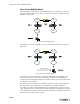
The BSC Secure Mobility setup page appears as shown in Figure 14-9.
2. Mark the Enable Secure Mobility checkbox to enable Secure Mobility on the Mobility
Node.
3. Set the BSC role to Secure Mobility Node by marking the Act as a mobility node and
receive the mobility node list from a central master? radio button.
4. Enter the protected interface IP address of the Secure Mobility Node List Master BSC
in the Master IP Address field.
5. Mark the Acquire initial Security Mobility Node List from Master checkbox to acquire
the latest snapshot of the node list from the Nodelist Master.
6. Enter a text string in the Secure Mobility mesh key field.
The mesh key is a common, shared password that you provide for all BSCs
participating in the Secure Mobility setup. The BSCs exchange the key when
communicating with each other, thus providing an extra layer of security. The key can
Figure 14-9: BSC Secure Mobility Setup Page