
Specifications


Load Sharing
BlueSecure™ Controller Setup and Administration Guide 14-19
sharing feature on up to six members of the local replication configuration including the
Replication Master by following these steps.
)
Note: Before configuring LoadSharing or performing the following three stepes, create all
the VLANs that you wish to use on
all
LoadSharing Nodes. If a VLAN exists on one node,
it must exist on all boxes
with the same VLAN id
.
1. Define the IDs and virtual network addresses to be assigned to members of the load
sharing group on the Load Sharing Master.
2. Configure and enable load sharing on the Load Sharing Master (i.e., the Replication
Master) and then connect its failover port to the failover switch.
3. Connect each Load Sharing Node BSC to the switch that interconnects the BSC
failover ports and then configure load sharing on each Load Sharing Node.
Each of these steps is described in detail in the sections that follow.
Step 1: Define the IDs and virtual network addresses to be assigned to members of the
load sharing group.
On the Load Sharing Master (i.e., the Replication Master), follow these steps to define the
load sharing group members:
1. Click the Mobility MatriX tab in the BSC administrator console, and then click the
Load Sharing Nodes tab.
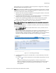
The Load Sharing Nodes page appears. Note that the first three VLANs (if any) are
shown in this tab. They are listed from left to right in groups of three colums
(managed address, managed netmask, protected address). The super text above the
columns for a VLAN indicates the VLAN name and grouping. For example:
2. Complete the following steps for each BSC that is to have membership in the load
sharing group:
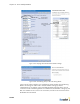
a) Click the icon that corresponds to the LSG member settings that you wish to
edit.
The Edit a load sharing entry page appears, as shown in Figure 14-18.
When you initially set up the LSG, we recommend that you proceed in numeric
order by ID and that you map the settings associated with ID 1 to the Load
Sharing Master.
Figure 14-17: Load Sharing Nodes Page