
Specifications


Chapter 2: Installation
2-4
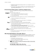
BSC-2200/3200/5200 Displays, Controls, and Connectors
The following figure shows the Bluesocket BSC-5200 front and rear panel displays,
controls, and connectors.
Status LEDs The Bluesocket BSC-2200/3200/5200 provides the following front-panel status LEDs:
• PWR - Lights when the BSC is connected to an AC power source and its rear-panel
power switch is in the closed position (|).
• DISK - Flickers when the BSC is writing data to or reading data from non-volatile
memory.
LCD The BSC provides a 2x16 character, liquid crystal display (LCD) to display the IP address
configured for its protected interface.
Power Control If the BSC is running and you press the front-panel Power button, the BSC will stop all
active services after a slight delay. After all services are shutdown, the BSC executes its
normal power-down sequence and shuts off completely.
Restart Control If the BSC is running and you press the front-panel Restart button, the BSC will stop and
then restart all active services automatically. In approximately 30 to 60 seconds after you
have pressed the Restart button, the LCD display will indicate that BSC services have re-
started.
Serial Port The BSC provides a serial port equipped with a DB-9, male connector to support local
console configuration of the BSC. Normally, you will never use the BSC serial port. You
should configure the BSC via its serial interface only in the rare event that you lose access
to the BSC’s web interface due to an Internet service outage. The BSC serial interface
supports only a subset of the BSC’s configurable parameters. See “Serial Port Access to
Essential Functions” on page D-1 for details about accessing the BSC serial interface.
Fail Over Port Use the Fail Over port to connect the BSC to another BSC via Ethernet for failover
operation. The Fail Over port is equipped with a copper, RJ-45 10/100/1000 Mbps
Ethernet connector. Use a crossover cable with no switches or hubs in between to connect
the two failover BSCs directly together.
Configuration of the BSC for failover operation is described in “Configuring Failover
Parameters” on page 4-25.
Figure 2-1: BSC-2200/3200/5200 Displays, Controls, and Connectors