
Specifications


Chapter 4: Networks
4-12
NAT the
addresses to the
protected
interface
address
Mark this checkbox to activate Network Address Translation (NAT) to map all client IP
addresses on the managed side to the IP address of the BSC protected interface. Clear
this checkbox to disable NAT.
)
Note: If the BSC managed IP subnet is different from the protected IP subnet and NAT is
not enabled, then you must configure static routes on your network routers to reach the
managed network. These static routes would point to the BSC’s protected interface as
their next “hop.”
See “Configuring the BSC to Assign Fixed IP Addresses” on page 4-14 for information
about mapping an individual wireless client IP address to a specific device IP address on
the protected side.
Enable multicast
for this interface
Mark this checkbox to enable use of distance vector multicast routing protocol (DVMRP or
PIM-SM) for this interface.
Force proxy ARP
for this interface
Mark this checkbox to enable the BSC to force proxy address resolution protocol (ARP)
for traffic directed to clients behind the protected interface.
You should enable this option only when the protected interface and the managed
interface reside within the same IP subnet. If this checkbox is cleared, the BSC determines
whether the network setup requires proxy ARP.
Port settings By default, the BSC's physical interfaces automatically negotiate bit rate and duplex type
for connections. However, if required, you can specify interface speed and duplex type
here. Max indicates the highest speed supported by an interface (for example, the BSC-
2100 protected interface supports a speed of1000 Mbps maximum).
Display Specify which login page to display to users logging into the BSC on the managed
interface—the default user login page or a customized page you have defined. See
“Customizing the User Login Page” on page 11-2 for information about creating a
customized user login page.
7. Click Save to save the settings to the BSC database.
8. Click the DHCP Server link at the top of the page.The DHCP settings for managed
interface (eth1) page appears as shown in Figure 4-8.
9. Configure the BSC DHCP server settings, as appropriate for your network:
Address range
to dynamically
assign
Optional. Enter range of addresses that DHCP can assign within a network address
space from first to last, such as 192.168.162.20 to 192.168.162.50.
Leaving this field blank means that DHCP can assign any addresses within the subnet
defined by the IP address and Netmask fields on the Edit managed interface (eth1)
page.
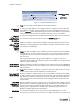
Figure 4-7: Enabling the BSC DHCP Server
Clear this Checkbox
Mark this Checkbox