
Specifications


Chapter 2. Setting Up the Express 3000 SP
2-6 Express 3000 SP User Manual 61203153L3-20
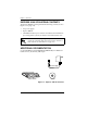
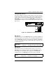
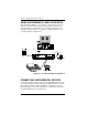
Rear Panel
The Express 3000 SP Rear Panel contains all of the interfaces used in
connecting your unit and two DIP switches that set the DTE rate and
reset your unit (see Figure 2-2). Please read carefully the section
Set-
ting the DIP Switches
on page 2-7. Appendix D describes the pinouts
for these interfaces.
Figure 2-2. Express 3000 SP Rear Panel
Table 2-1. Express 3000 SP LED Descriptions
LED Color Description
TD Green Transmit Data (TxD).
RD Green Received Data (RxD).
1 or 2 Solid Green POTS 1 or 2 in use -- local powering.
Identifies Life Line POTS interface --
span powering
Off Ready. No data traffic.
Solid Amber B channel 1 or 2 passing data.
Amber Flash Remote test originate.
PWR/LINE Solid Green Local powering with span power
present.
Off No local power and maybe no span
power (see LED 1 or 2 above).
Flashing Local power but no power from the
span.
OFF
EIA232
PWR
ISDN
21
12
ON
42VDC
EIA-232 Port
Power Supply
Connector
DIP
Switches
POTS
Port 1
POTS
Port 2
ISDN
Interface