ISU 512 ISDN Service Unit USER MANUAL Part Number ISU 512 (U Interface) ISU 512 ST (ST Interface) RS-530 to V.35 Adapter RS-366 Y Cable RJ-45 to DB-25 Adapter 61202.086L1-1B September 1997 1202086L1 1202086L2 1200072L1 1200120L1 3196.
Trademark: 5ESS is a registered trademark of AT&T DMS-100 is a trademark of Northern Telecom, Inc. ISU is a trademark of ADTRAN, Inc. 901 Explorer Boulevard P.O. Box 140000 Huntsville, AL 35814-4000 Phone: (205) 963-8000 © 1997 ADTRAN, Inc. All rights reserved. Printed in USA.
FCC regulations require that the following information be provided in this manual: 1. This equipment complies with Part 68 of the FCC rules. On the bottom of the equipment housing is a label that shows the FCC registration number and Ringer Equivalence Number (REN) for this equipment. If requested, provide this information to the telephone company. 2. If this equipment causes harm to the telephone network, the telephone company may temporarily discontinue service.
FEDERAL COMMUNICATIONS COMMISSION RADIO FREQUENCY INTERFERENCE STATEMENT 1202086L1 This equipment has been tested and found to comply with the limits for a Class B digital device, pursuant to Part 15 of the FCC Rules. These limits are designed to provide reasonable protection against harmful interference in a residential environment.
CANADIAN EMISSIONS REQUIREMENTS 1202086L1 This digital apparatus does not exceed the Class B limits for radio noise emissions from digital apparatus as set out in the interference-causing equipment standard entitled "Digital Apparatus," ICES-003 of the Department of Communications.
CANADIAN EQUIPMENT LIMITATIONS Notice: The Canadian Industry and Science Canada label identifies certified equipment. This certification means that the equipment meets certain telecommunications network protective, operational, and safety requirements. The Department does not guarantee the equipment will operate to the user’s satisfaction. Before installing this equipment, ensure that it is permissible to be connected to the facilities of the local telecommunications company.
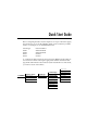
Quick Start Guide Before configuring the ISUTM 512, the telephone service provider must supply the switch type, service profile identifier (SPID), and local directory number (LDN). For example, for one ISDN BRI 2B+D line: Switch Type SPID1 SPID2 LDN1 LDN2 National ISDN-1 20455512120100 20455512130100 5551212 5551213 To configure the ISU 512 from the front panel press Enter from the initial status screen and continue entering the appropriate numbers until the Switch type, SPIDs and LDNs have been entered.
Press Cancel to exit to the status screen and verify Ready conditions for each BRI line configured. If the status screen reads SYNC, DOWN, TEI, or SPID, either the configuration of the switch type and SPIDs are incorrect or there may be a problem with the ISDN line or translations; see the chapter Troubleshooting. Outside of the U.S. and Canada, only the LDNs will need to be entered.
Table of Contents Chapter 1. Understanding ISDN and the ISU 512 ..................................................... ISDN Overview .................................................................................................................. Product Overview .............................................................................................................. ISU 512 Interoperability ....................................................................................................
Table of Contents Data 56 kbps.......................................................................................................... Data 64 kbps.......................................................................................................... Terminal Identification ............................................................................................... Setting the SPID.................................................................................................... Setting the LDN...
Table of Contents TXINIT .......................................................................................................................... TXFA.............................................................................................................................. TXADD01...................................................................................................................... TXDEQ ....................................................................................................
Table of Contents Rate Adaption ................................................................................................ Interoperability .............................................................................................. D Channel Switch Compatibility ................................................................ B Channel Aggregation ................................................................................ Display ...............................................................
List of Figures Figure 1-1: Figure 1-2: Figure 3-1: Figure 3-2: Figure 3-3: Figure 3-4: Figure 3-5: Figure 3-6: Figure 4-1: Figure 4-2: Figure 4-3: Figure 5-1: Figure 5-2: Figure 5-3: Figure 5-4: Figure 5-5: Figure 6-1: Figure D-1: Figure D-2: Figure D-3: Figure D-4: Figure D-5: Figure D-6: 61202.086L1-1 ISU 512 Rear Panel ..................................................................................... 2 ISU 512 (U interface) Applications ..........................................................
Table of Contents vi 61202.086L1-1 User Manual 61202.
List of Tables Table 1-A: Table C-A: Table D-A: Table D-B: Table D-C: Table D-D: Table D-E: Table D-F: 61202.086L1-1 ISU 512 Synchronous Rates ...................................................................... 5 AT Commands ............................................................................................ 85 Pinouts for Chain In and Chain Out Ports ............................................. 89 Pinouts for IFC RJ-45 Connectors ............................................................
Table of Contents viii 61202.086L1-1 User Manual 61202.
Chapter 1 Understanding ISDN and the ISU 512 ISDN OVERVIEW The Integrated Services Digital Network (ISDN) is a public or private switched digital network. ISDN is an international standard for digital communications, allowing a full range of enhanced services supporting voice, data, and image applications through standard interfaces over a single pair of telephone wires.
Chapter 1: Understanding ISDN and the ISU 512 The ISU 512 transmits data over an RS-530 or V.35 interface, selectable from the front panel. The ISU 512 performs at synchronous data transfer rates of 56 kbps to 512 kbps. At rates over 64 kbps, the BONDING Mode 1 inverse multiplexing protocol synchronizes data over up to eight 64 kbps B channels. By supporting BONDING, the ISU 512 interoperates with other BONDING-compatible inverse multiplexers and ISDN terminal adapters.
Chapter 1: Understanding ISDN and the ISU 512 Dialing from the ISU 512 is accomplished in a variety of ways: • • • • • • Manually from the front panel keypad. Manually from up to ten stored numbers. Automatically through an RS-366 dialing port used in video conferencing applications; a special RS-366 Y cable provides the two RS-366 interfaces for this application (part number 1200120L1). V.25 bis in-band dialing (used in applications such as LAN/WAN bridging). Dialing while DTR is enabled.
Chapter 1: Understanding ISDN and the ISU 512 ISU 512 INTEROPERABILITY Telephone networks are evolving from analog technologies to digital technologies such as ISDN. This transition is time-consuming and costly for telephone companies and upgrading all locations and facilities is a lengthy process. The ISU 512 bridges this transition by supporting communications with existing and future network services and equipment.
Chapter 1: Understanding ISDN and the ISU 512 RECOMMENDED OPERATING PROTOCOLS The ISU 512 supports BONDING Mode 1. For applications such as videoconferencing, in which the unit needs to interoperate with two SW56 lines or one dual-port ISDN device, the 2 x clear channel protocol (dual-port mode) is used. The ISU 512 automatically uses the 2 x clear channel protocol whenever it does not find a BONDING partner. The first call (incoming or outgoing) connects to the V.35 port in 2 x clear channel protocol.
Chapter 1: Understanding ISDN and the ISU 512 6 ISU 512 User Manual 61202.
Chapter 2 Ordering ISDN ISDN is a complex service with many network options. Obtaining service from the local telephone company and long distance providers can be complicated. The following instructions only apply to North American switches. In North America, the development of ISDN Ordering Codes (IOCs) simplifies the process of ordering ISDN service.
Chapter 2: Ordering ISDN For more information regarding ordering ISDN, see the ADTRAN document Ordering ISDN Service User Guide part number 60000.015-8, or contact the telephone company for alternative line configurations. The Ordering ISDN Service User Guide is available on the ADTRAN home page at http://www.adtran.com (go to the Service and Support page and then to the ISDN Information Desk) or by calling ADTRAN at (205) 963-8000. 8 ISU 512 User Manual 61202.
Chapter 3 Installation INSTALLATION After unpacking the unit, immediately inspect it for possible shipping damage. If damage is discovered, file a claim immediately with the shipping carrier, then contact ADTRAN Customer Service; see the inside back cover of this manual for phone numbers. NETWORK CONNECTION The ISU 512 (U interface) supports either Dial or Leased operation. The ISU 512 (ST interface) supports only Dial operation.
Chapter 3: Installation DTE DATA CONNECTION Data terminal equipment (DTE) is connected to the ISU 512 by using the V.35 interface, and/or the RS-530 interface on the rear panel of the ISU 512. The maximum cable lengths recommended are 50 feet for the RS-530 interface, or 150 feet for the V.35 interface. The pin assignments for the DTE interfaces are shown in the appendix Pinouts. The RS-530 interface and the V.35 interface support data rates up to 512 kbps.
Chapter 3: Installation Where #R changes the Channel Rate (number of ISDN B channels) as follows: 0 = (2x56k and 2x64k) 2 x Clear Channel Protocol 1 = 1 B Channel (1x56k, 1x64k) BONDING Mode 1 2 = 2 B Channels (2x56k, 2x64k) BONDING Mode 1 3 = 3 B Channels (3x56k, 3x64k) BONDING Mode 1 4 = 4 B Channels (4x56k, 4x64k) BONDING Mode 1 5 = 5 B Channels (5x56k, 5x64k) BONDING Mode 1 6 = 6 B Channels (6x56k, 6x64k) BONDING Mode 1 7 = 7 B Channels (7x56k, 7x64k) BONDING Mode 1 8 = 8 B Channels (8x56k, 8x64k) BOND
Chapter 3: Installation THE MAINTENANCE INTERFACE The Maintenance Interface is available at 9600 bps, 8 data bits, no parity, through the CHAIN IN port. See the appendix Pinouts for the Chain In port pinout. The VT 100 terminal or null modem can be connected to the Chain In port using the RJ-45 to DB-25 adapter (part number 3196.ADPT003) and the RJ-45 to RJ-45 cable provided with the unit. The port contains transmit and receive data (EIA-232 compatible).
Chapter 3: Installation Software Update There are two methods available for updating ISU 512 software. The local method involves using the Chain In port and is described in this section. The remote method involves transmitting smart dial strings over a dial-up connection and is described in the section Remote Access of the chapter Configuration. The ISU 512 contains Flash memory allowing the software to be updated using the Chain In port.
Chapter 3: Installation VT 100 MENU INTERFACE The VT 100 menu interface can be used by connecting a VT 100 compatible terminal to the Chain In port on the back of the ISU 512. The VT 100 terminal (or PC running terminal emulation software) is connected to the Chain In port using the RJ-45 to DB-25 adapter (part number 3196.ADPT003) and the RJ-45 to RJ-45 cable provided with the unit. See the appendix Pinouts for the Chain In port pinout information.
Chapter 3: Installation Figure 3-2 VT 100 Configuration Menu Figure 3-3 VT 100 Configuration Menu 2 61202.
Chapter 3: Installation Figure 3-4 VT 100 Status Screen Figure 3-5 VT 100 Test Menu 16 ISU 512 User Manual 61202.
Chapter 3: Installation Figure 3-6 VT 100 Dial Menu 61202.
Chapter 3: Installation 18 ISU 512 User Manual 61202.
Chapter 4 Operation INITIAL SELF TEST The ISU 512 performs an initial self test upon initial installation. Once the self test is successfully completed, the current status mode is displayed. If the ISU 512 is not connected to the network, the Status menu displays DOWN next to the network connection number. If the unit is connected to the network and functioning properly, READY is displayed next to the network connection number; see Figure 4-1.
Chapter 4: Operation MENU STRUCTURE The ISU 512 uses a multilevel menu approach to access its many features. All menu operations are displayed in the LCD window or are available from the VT 100 terminal interface. The opening menu is the access point to all other operations. There are four Main menu branches: Status, Test, Configuration, and Dial. Each Main menu item has several functions and submenus to identify and access specific parameters.
Chapter 4: Operation Configuration (CONFIG) Menu Configuration selects network and DTE operating parameters. Dial Menu Dial provides manual dialing functions. Key in a number to dial or select one of the ten stored numbers. Basic Menu Traversal Four function keys on the left side of the ISU 512 keypad allow the various menu branches to be entered, exited, and scrolled through. The four function keys are defined below: Enter Up Arrow Down Arrow Cancel Selects flashing menu item. Scrolls up the menu tree.
Chapter 4: Operation 3. 4. Choose an item on the submenu such asNetwork Options (Netw. options) by pressing the corresponding number followed by Enter. To select Dial Line options, press 1, then press Enter. The menu path follows: 3=CONFIG 1=Netw. options 1=Dial Line 4=Dial Options It is important to note that some features in the ISU 512 do not immediately take effect upon selection. This prevents unintentional reconfiguration of the ISU 512 during an active call.
Chapter 4: Operation LCD Window Displays menu items and messages in 2 lines by 16 characters. Enter Selects active menu items. To select a menu item, press the number of the item to activate. When the menu item is flashing, press Enter to select it. A submenu item is invoked or a configuration parameter is set. Numeric Keypad The numeric keypad contains the numbers 0 through 9, which are used to activate menu items and enter parameters. Cancel Stops the current activity and returns to the previous menu.
Chapter 4: Operation 24 ISU 512 User Manual 61202.
Chapter 5 Configuration USING ISDN BASIC RATE SWITCHED SERVICE This section explains how to configure the ISU 512 when using ISDN Basic Rate switched service. Figure 5-1 illustrates the entire Configuration branch of the menu tree. 61202.
Chapter 5: Configuration 1=STATUS 2=TEST 1=Loopback DTE 2=Loopback Proto 3=2047 Checker 4=NEBE/FEBE 5=Software Ver 1=Switch type 1=AT&T 5ESS 2= DMS-100 3=National ISDN1 4=NEC Switch 5=EuroISDN (only available on the ISU 512 ST) 2=Call type 1=Speech 2=Audio 3=Data 56Kbps 4=Data 64Kbps 3=Terminal ID Set SPID
Chapter 5: Configuration CONFIGURING NETWORK OPTIONS FOR DIAL OPERATION This section describes how to configure the ISU 512 for Dial operation such as Switch type, Call type, Terminal ID, Dial options, and Auto answer. To dial calls over ISDN, the ISU 512 must be configured for Dial Line. Switch Type Find out what kind of ISDN switch the local CO is using by asking the telephone administrator or the telephone company representative.
Chapter 5: Configuration Speech Speech directs the call control software to request a Mu-law/A-law speech circuit as the bearer capability for outgoing calls. The Speech option is used with an ISDN line configured for voice service. In some areas voice service costs less than data service. A Speech call type does not guarantee an end-to-end digital connection with some local and long distance carriers. Audio Audio directs the call control software to request a 3.
Chapter 5: Configuration Terminal Identification Terminal identification is assigned by the local telephone company. Use the following menu path to set the terminal identification. 3=CONFIG 1=Netw. options 1=Dial Line 3=Terminal ID 1=Set SPID 2=Set LDN Setting the SPID The service profile identifier (SPID) is a sequence of digits used to identify ISDN terminal equipment to the ISDN switch.
Chapter 5: Configuration Setting the LDN The local directory number (LDN) is used when placing or receiving BONDING calls. The LDN is the local phone number assigned to the line. This option allows the entry of up to eight LDNs. Use the Up and Down arrows to select the LDN to enter.
Chapter 5: Configuration 1=1 sec or EON 1=Switch type 2=2 sec or EON 2=Call type 3=CONFIG 1=Netw. options 1=Dial Line 3=Terminal ID 1=Front Panel 2=DTE options 2=Leased Line 4=Dial options 2=RS-366 3=BONDING setup 5=Auto answer 4=Quick setup 6=Connect Timout 3=5 sec(default) 1=RS366 Time 4=10 sec or EON 5=20 sec or EON 6=Wait for EON 7=Call Screening 8=Passwords 2=Security 9=Maint Setup 1=enabled 2=disabled 0=Call NumID 3=V.
Chapter 5: Configuration 5 sec or EON (default) The ISU 512 assumes the dial string is fully entered if more than 5 seconds elapse since input of the last digit, or an EON command is received. This is the factory default setting. 10 sec or EON The ISU 512 assumes the dial string is fully entered if more than 10 seconds elapse since input of the last digit, or the unit receives the EON command.
Chapter 5: Configuration Auto Answer The ISU 512 can be configured to automatically answer or not answer. Use the following menu path: 3=CONFIG 1=Netw. options 1=Dial Line 5=Auto answer 1=Disabled 2=Enabled (default) 3=Dump all calls Disabled When Disabled is selected, the ISU 512 does not answer incoming calls. The ringing call can be dumped using the Hang Up Line command. Disable Auto Answer if V.25 bis is in control of answering incoming calls with the CIC/DIC commands; other settings override V.
Chapter 5: Configuration Connect Timeout The Connect Timout option sets the length of time that the ISU 512 waits for a far-end unit to answer an outgoing call. Use the following menu path: 3=CONFIG 1=Netw. options 1=Dial Line 6=Connect Timout 1=15 sec 2=30 sec (def) 3=1 Minute 4=2 Minute 5=4 Minute Call Screening Call Screening allows the ISU 512 to answer all incoming calls (default) or only calls originating from phone numbers stored in the DIAL menu as stored numbers SN0 through SN9.
Chapter 5: Configuration 3. 4. 5. Place a call to the ISU 512 with the stored number to see if it answers. If the ISU 512 does not answer the call, look at the Call ID message in the Status buffer. More than likely, the Call ID number is a ten-digit number Store the number in SN0 as it is displayed in the Call ID message and test Call Screening again.
Chapter 5: Configuration Remote Supervision The ISU 512 has the ability to be remotely accessed and configured from another ISU 512. The originating ISU 512 can remotely access another ISU 512 using a smart dial string with a #6 suffix. The ISU 512 can be protected from illegal access by using the password protection built into the remote protocol. The Supervision (SPV) password can be accessed in the menu tree at: 3=CONFIG 1=Netw.
Chapter 5: Configuration Maintenance Setup There are three Maintenance Setup options: Auto Traps, ADLP Address, and Port Mode. Auto Traps Auto Traps is for use with Port Mode=ATEL. The ISU 512 monitors and reports alarms for network failures or degrading performance conditions. The ISU 512 can be configured to generate protocol traps autonomously by selecting Enable. To disable protocol traps, select Disable.
Chapter 5: Configuration Call NumID When Call NumID is enabled, the ISU 512 will send the caller ID INFO setup message to the ISDN switch. When Call NumID is disabled, the caller ID INFO setup message will not be sent to the ISDN switch. 38 ISU 512 User Manual 61202.
Chapter 5: Configuration CONFIGURING THE ISU 512 FOR LEASED DIGITAL SERVICE This section explains how to configure the ISU 512 when using a 2B1Q Leased Digital service or a service that provides a permanent connection between end points. This mode is only supported by the ISU 512 (U interface). Selecting Leased Line configures the unit for leased line service or service that provides a permanent connection between end points such as limited distance modem or LDM service; see Figure 5-3. 3=CONFIG 1=Netw.
Chapter 5: Configuration 18,000 ft MIXED GAUGE WIRE DTE LEASED MASTER LEASED SLAVE DTE Figure 5-4 Limited Distance Modem Application If two ISU 512 units are connected through channel banks, one unit should be configured for Slave mode and the other for Slave (Master); see Figure 5-5. To easily configure ISU 512s for this application, one unit can be optioned using Quick Setup, Leased Slave and the other can be optioned using Quick Setup, Leased Slave(Master).
Chapter 5: Configuration Test Remote When the Test Remote option is enabled the unit performs an automatic 2047 BERT of the line(s) immediately following BONDING connection. When disabled (default), no test is performed after initialization. Maintenance Setup There are three Maintenance Setup options: Auto Traps, ADLP Address, and Port Mode. Auto Traps The Auto Traps option is for use with Port Mode=ATEL. The ISU 512 monitors and reports alarms for network failures or degrading performance conditions.
Chapter 5: Configuration SETTING DTE OPTIONS The DTE Options menu is used to select the configuration parameters that control the operation of the DTE interface ports of the ISU 512, such as the maximum bit rate and the connector type. Changes to the DTE options affect both ports (RS-530 and V.35) during dual-port mode and single-port modes of operation. Maximum Bit Rate The DTE bit rate can be set for 64K MODE 1 or 56K MODE 1.
Chapter 5: Configuration Connector Type Specify the interface by selecting the desired connector type. Use the following menu path to select the connector type. 3=CONFIG 2=DTE options 2=Connector Type 1=RS-530 2=V.35 (default) RS-530 to V.35 Cable The RS-530 to V.35 cable (part number 1200072L1) must be enabled for some dual-port applications, such as videoconferencing. Setting this option to Enabled allows the use of the RS-530 to V.35 cable. This cable converts the RS530 connector to a V.35 interface.
Chapter 5: Configuration CTS Options Selecting Forced CTS causes the CTS signal on the DTE connector to be continually asserted. Follow RTS causes the CTS signal to follow the state of the RTS lead. Follow CD causes the CTS signal to follow the state of the CD lead. Off V.25 ANSR drives CTS off while answering a call with V.25 bis dialing enabled. This setting is used for Panasonic video conferencing equipment with V.25 bis dialing enabled.
Chapter 5: Configuration 3=CONFIG 2=DTE options 7=DTR Options 1=Ignore DTR (default) 2=Idle when Off 3=Off>On dial #0 4=Dial #0 if On 5=Answer if On To store a number for automatic dialing see Dialing Options. Selecting Dial #0 if On allows calls to be automatically established when the DTR signal is in the active state. The unit attempts to establish a call using SN0-SN4 until the call is established or DTR goes inactive.
Chapter 5: Configuration BONDING SETUP The ISU 512 communicates with many different types of telecommunication equipment including other ISU 512s, ISDN terminal adapters, Switched 56 DSUs, and BONDING mode 1-compatible inverse multiplexers. The ISU 512 supports the BONDING mode 1 (Bandwidth on Demand Interoperability Group) adaptation protocol. See Recommended Operating Protocols in this chapter for more information on recommended modes of operation.
Chapter 5: Configuration TXFA This option specifies the length of time both endpoints attempt to detect the BONDING frame pattern when a call is connected before deciding the BONDING call has failed. This timer value should be left at the factory default setting of 10 seconds. However, when interoperating with other manufacturers’ BONDING equipment, it may be necessary to lengthen this timer so that it matches TXADD01. Select from values of 1, 2, 5, 10 (default), 20, 50, 100, and 200 seconds.
Chapter 5: Configuration TCID This option specifies the length of time both endpoints attempt to negotiate an agreeable value for bearer channels and channel capacities before deciding the BONDING call has failed. This timer default setting is 5 seconds. Values of 1, 2, 5 (default), 10, 20, 50, 100, and 200 seconds can be selected. Call Stagger This option specifies the amount of delay placed between calls. The default setting is 0 ms (no delay).
Chapter 5: Configuration TRANSPARENT 2 X CLEAR CHANNEL PROTOCOL Due to the large number of existing videoconferencing circuits that utilize dual-port terminal adapters or two SW56 DSU/CSU units, the ISU 512 has been designed to operate with these existing circuits by using a transparent 2x56/64 Clear Channel protocol. During incoming and outgoing calls, the ISU 512 attempts BONDING mode 1 protocol first.
Chapter 5: Configuration Videoconferencing equipment should be set for delayed second call dialing when using the RS-366 Y cable for dialing 2-clear channel calls. QUICK SETUP CONFIGURATION To configure the DTE Options quickly and easily, the Quick Setup menu is available to automatically set up the eight most common DTE configurations.
Chapter 5: Configuration Dial 384K When the ISU 512 is configured for Dial 384K service the following parameters are automatically preset: Service type Automatic answering ISDN call type Dial options Maximum bit rate DTR options RS-530-V35 cable RS-366-Y cable ISDN dial line Enabled 64 kbps data Front panel 384 kbps Ignore Disabled Disabled Dial 448K When the ISU 512 is configured for Dial 448K service the following parameters are automatically preset: Service type Automatic answering ISDN call type Dial
Chapter 5: Configuration Maximum bit rate DTR Options RS-530-V35 cable RS366-Y cable 336 kbps Ignore Disabled Disabled Video 384K When the ISU 512 is configured for Video 384K the following parameters are automatically preset: Service type Automatic answering ISDN call type Dial options Maximum bit rate DTR options RS-530-V35 cable RS-366-Y cable ISDN dial line Enabled 64 kbps data RS-366 384 kbps Idle when Off Enabled Enabled Video 336K When the ISU 512 is configured for Video 336K the following param
Chapter 5: Configuration Maximum bit rate DTR options Clock mode Channel rate RS-530-V35 cable RS-366-Y cable 512 kbps data Ignore Master 64K Bearer Disabled Disabled Leased Slave and Ldm SlvMstr When the ISU 512 is configured for Leased Slave or Ldm SlvMstr (limited distance modem slavemaster) the following parameters are automatically preset: Service type Automatic answering Maximum bit rate DTR options Clock mode Channel rate RS-530-V35 cable RS-366-Y cable 61202.
Chapter 5: Configuration DIALING OPTIONS Selecting 4=DIAL or pressing the # (pound) from the top of the menu tree displays the available dialing options. (See Figure 5-3.) Use the following menu path to set dialing options: 4=Dial 1=Hang up line 2=Dial number 3=Redial last # 4=Answer Call 5=Dial stored # 6=Store/Review # Hang Up Line Terminates current call. Dial Number Allows a number to be entered and dialed from the key pad.
Chapter 5: Configuration Store/Review Number Enter and review stored numbers. Press the Up and Down arrow keys to scroll through the 10 stored numbers (SN0 - SN9). To store a number, scroll in the desired stored number location, enter the number, and press Enter to save. If a mistake is made, press Cancel to clear the line and allow another attempt. Press Cancel twice in succession to exit without changing the selected stored number. 61202.
Chapter 5: Configuration CONFIGURING THE ISU 512 FOR V.25 BIS IN-BAND DIALING V.25 bis dialing is used primarily by data terminal equipment with synchronous interfaces (HDLC/SDLC or BSC/BISYNC) not supporting the AT command set, which is commonly used by asynchronous devices. The ISU 512 supports V.25 bis in-band dialing in accordance with Fascicle VIII.I - V.25 bis (Malaga-Torremolinos 1984, Melbourne 1988). Recommendation V.
Chapter 6 Testing TEST OPTIONS Selecting 2=TEST from the Main menu tree displays available local testing options. Use the following menu path to select test options: 2=Test 1=Loopback DTE 2=Loopback Proto 3=2047 Checker 4=NEBE/FEBE 5=Software Ver Loopback DTE Causes both DTE ports to loopback toward user equipment. This allows performance of a bit error rate test (BERT) between the ISU 512 and end user equipment to verify proper cable connection, etc.
Chapter 6: Testing 2047 Checker The ISU 512 has the ability to loopback the remote unit and generate/check 2047 BERT pattern through the BONDING protocol. This allows 2047 BERT patterns to be run on multiple ISDN connections (through BONDING). The originating ISU 512 generates the 2047 patterns and checks the incoming pattern for errors. The test is run for a period of time defined in S-register 26. The larger the value in S26 the longer the test runs before entering data mode.
Chapter 6: Testing Near-End Block Errors/Far-End Block Errors (NEBE/FEBE) Allows the user to monitor the quality of the local loop by viewing the number of near-end block errors (NEBE) and far-end block errors (FEBE) occurring on the ISDN U-interface. An incrementing count of NEBEs indicates a problem on the local loop from the switch to the NT-1. An incrementing count of FEBEs indicates a problem on the local loop from the NT-1 to the switch. A call does not have to be placed to use the NEBE/FEBE counter.
Chapter 6: Testing 60 ISU 512 User Manual 61202.
Chapter 7 Troubleshooting IF SELF TEST FAILS When the ISU 512 powers up, it performs an internal self test. This takes approximately 10 seconds. At the end of the test, the front panel displays Self Test Passed. If Self Test Passed is not displayed, perform the following procedure to verify if the problem can be solved locally: 1. Ensure the ISU 512 is receiving power and is switched On. 2. Turn Off the ISU 512; while holding the 0 key, power up the ISU 512.
Chapter 7: Troubleshooting directory number(s) provided with the ISDN line. Calling a good ISDN line with nothing connected usually results in a ring or fast busy tone. If the call is completed or a not-in-service intercept is received, then there is probably something wrong with the translation of the ISDN line. Contact the phone service provider for help. 3. If the ISU 512 continues to read DOWN, there is a physical problem with the ISDN line (probably Layer 1 setup).
Chapter 7: Troubleshooting F. Ensure nothing else is bridged across the ISDN line pair. G. With a minimum of extra wiring, try connecting to the line pair at the point where service provider's wiring ends. H. With the ISU 512 connected to the ISDN line and powered up, contact and inform the service provider's repair group that your ISDN basic rate line has a Physical Layer 1 problem. Request the ISDN line be checked.
Chapter 7: Troubleshooting 3. Connect another piece of functioning ISDN equipment to the ISDN line. 4. With the ISU 512 connected to the ISDN line and powered up, talk to your service provider's repair group and tell them you have an ISDN basic rate line that appears physically OK but has no terminal endpoint identifier (TEI). Ask them to check the line translation and ensure that ISDN the line supports Dynamic TEI allocation.
Chapter 7: Troubleshooting IF THE DISPLAY READS SPID{1,3,5, OR 7} This section does not apply to installations outside of North America. If the ISU 512 reads SPID1, then the ISU 512 is physically connected to the local telephone service provider and has established Logical Layer 2. The ISU 512 is unable to establish layer 3.
Chapter 7: Troubleshooting • • The ISU 512 software setup The software setup of the telephone service provider To isolate the problem, perform the following procedure. 66 1. Ensure the ISU 512 is set up with the correct SPID and LDN by selecting CONFIG, Netw. options, Dial Line, Terminal ID, and SPID/LDN. 2. Try swapping SPID1 with SPID2 and LDN1 with LDN2, SPID3 with SPID4 and LDN3 with LDN4, SPID5 with SPID6 and LDN5 with LDN6, and SPID7 with SPID8 and LDN7 with LDN8.
Chapter 8 Specifications Summary SPECIFICATIONS AND FEATURES This section describes the standard specifications and features incorporated in the ISU 512. Network Interface Four RJ-45s for ISDN Basic Rate Interface DTE Interface RS-530 or V.35 (both connectors present) Dialing Selections • Manual or automatic stored number dialing, DTR assertion • V.
Chapter 8: Specifications Summary D Channel Switch Compatibility • AT&T 5ESS • NTI DMS-100 • National ISDN-1 • EuroISDN (only available on the ISU 512 ST) B Channel Aggregation BONDING protocol Mode 1 Display Two-line x 16-character LCD Environmental • Operating temperature: 0 to 50 °C (32 to 122 °F) • Storage temperature: 20 to 70 °C (- 4 to 158 °F) • Relative humidity: Up to 95%, non-condensing Physical 2.25" H, 8.75" W, 11.
Appendix A Status Buffer Messages STATUS LINE MESSAGES Messages in all caps are generated by the ISDN network. Messages with lower case letters are generated by the ISU 512. Call Connect B1 Bearer channel 1 connected and is currently active. Call Connect B2 Bearer channel 2 connected and is currently active. NET REM LOOPBACK The ISU is performing a V.54 or DDS latching loopback toward the network. Disconnecting The current phone call is being disconnected (hung up).
Appendix A. Status Buffer Messages {1,2,3,4}:SPID1 The ISU is registering its first SPID with the network. {1,2,3,4}:SPID2 The ISU is registering its second SPID with the network. RINGING The phone number just dialed is ringing. BONDING nnnn BONDING mode 1 rate adaption is running at the bit rate specified by nnnn. BONDING Quitting BONDING mode 1 rate adaption protocol is turning off. BONDING Ready BONDING mode 1 rate adaption protocol is ready.
Appendix A. Status Buffer Messages ACCESS_INFO_DISC The network was unable to deliver access information to the far end. Bad AT bit field User issued an AT command with an argument that was out of range. Bad call type ISU 512 placed a call with an improper call type. Bad DTE baud The DTE bit rate does not match a valid bit rate for the protocol selected. Bad DTE bps Bonding negotiation determined that the chosen DTE bit rate is invalid. BAD_INFO_ELEM Call control error.
Appendix A. Status Buffer Messages CallID 2 in use ISU 512 tried to place a call using SPID 2 though SPID 2 was already in use. Call not ringing User executed an answer command (A) but there was not a call present. CALL_REJECTED The call has been rejected by the ISDN Network. CAP_NOT_IMPLEMENT The network or far end does not support the bearer capability requested. CHAN_DOES_NOT_EXI The user asked for a bearer channel that is not present.
Appendix A. Status Buffer Messages DPUMP END RCVD Indication of a hang-up or disconnect occurring during BONDING. Does not indicate an ERROR condition has occurred. DTE not set V25 The DTE equipment is not optioned for the same bit rate as the ISU 512 for V.25 bis dialing. DTR not up ISU 512 tried to place a call in a dialing mode that requires DTR to be in an active state but it is not. Dump call ISU 512 could not accept an incoming call because it was already involved in a call.
Appendix A. Status Buffer Messages INCOMING_CALL_BA Incoming call barred. The network will not allow an incoming call. INCOMPATIBLE_DEST The called number cannot accept the type of call that has been placed. INTRWORKING _UNS A message was sent by a far-end network that was not understood. INVALID_CALL_REF Call control error. INVALID_ELEM_CON Call control error. INVALID_MSG_UNSP Invalid message, protocol error. INVALID_NUMBER_F The dialed number has an invalid format.
Appendix A. Status Buffer Messages MANDATORY_IE_MIS Mandatory information element missing. Need 64K call The BONDING protocol requires the ISU 512 to be configured for a 64k data call type. Negotiation fail The BONDING negotiation has failed. NETWORK BUSY The ISDN switch is busy and unable to process a call. NETWORK_CONGESTI The phone network is currently congested. NETWORK_OUT_OF_O The phone network is out of order. NO_CIRCUIT_AVAIL The requested bearer channel is not available.
Appendix A. Status Buffer Messages NORMAL_CLEARING The network is disconnecting the current call. NOT end2end ISDN The path that the call was routed over is not ISDN from end-to-end (warning only). NUMBER_CHANGED The number dialed has been changed. OUTGOING_CALL_BA The network will not allow the outgoing call to be placed. PRE-EMPTED The network pre-empted the call. PROTOCOL_ERROR Call control error. REQ_CHANNEL_NOT_ The channel type requested is currently not available.
Appendix A. Status Buffer Messages TANULL expired Bonding timer TANULL expired; non BONDING equipment attempted to call into the ISU 512 while optioned for BONDING. TEMPORARY_FAILURE The network has temporarily failed; try the call again. TIMER_EXPIRY Call control error. TXADD01 expired Bonding timer TXADD01 expired, probably making a long distance call to a foreign country; adjust timer value to correct. TXFA1 expired Bonding timer TXFA1 expired; other vendor's BONDING equipment did not operate properly.
Appendix A. Status Buffer Messages WRONG_MSG_FOR_ST The ISU 512 received a message that is not appropriate for the state of the call. 530 Set Primary The connector type is set to RS-530. This may cause 2 x Clear Channel mode to fail to come on-line. 2 x Clear Channel mode only works when the connector type is set to V.35. 78 ISU 512 User Manual 61202.
Appendix B S-Register List S0 . . . . . AUTO ANSWER . . . . . . Determines how the ISU 512 answers an incoming call. 0=Disable (ISU 512 does not answer call) 1=Enable (ISU 512 answers all calls) (default) 2=Dump all calls S7 . . . . . CONNECT TIME. . . . . . Determines how long the ISU 512 waits for an outgoing call to be answered. 15=15 seconds 30=30 seconds (default) 60=1 minute 120=2 minutes 240=4 minutes S26 . . . . 2047 Test Time . . . . . . . .
Appenidix B. S-Register List S34 . . . .DTE DTR. . . . . . . . . . . . . Determines how the ISU 512 responds to changes in DTR. 0=Ignore DTR (default) 2=Dump incoming call when DTR is off 4=Hang-up incoming call when DTR is off 8=Hang-up outgoing call when DTR is off S35 . . . .DTE CONN . . . . . . . . . . . Determines which is the current operating DTE connector. 0=V.35 connector (default) 1=RS-530 connector S40 . . . .BOND TXINIT . . . . . . . .
Appenidix B. S-Register List S45 . . . . BOND TCID. . . . . . . . . . The number of seconds both end points attempt to negotiate agreeable values for bearer channels and channel capacities before deciding the BONDING call has failed. 0 to 256, 5 sec is default. S47 . . . . RS 366 TIME . . . . . . . . . Determines the amount of time the RS-366 port waits for either EON or inactivity to terminate a dial string before dialing a number.
Appenidix B. S-Register List S55 . . . .DIAL MODE . . . . . . . . . . Selects dialing interface. 0=Front panel only (dialing from front panel is always available) (default) 1=RS-366 dialing port 3=V.25 bis dialing S58 . . . .CALL SCREENING . . . . Allows the ISU 512 to screen incoming calls. 0=Answer any call (default) 1=Answer only calls from numbers matching those stored in SN0 through SN9 S88 . . . .RS-530 to V.35 Adapter Cable 0=Disable (default) 1=Enable S89 . . . .
Appenidix B. S-Register List The following are the string locations for stored numbers 0 - 9: SS90 . . . SN0 LOC SS91 . . . SN1 LOC SS92 . . . SN2 LOC SS93 . . . SN3 LOC SS94 . . . SN4 LOC SS95 . . . SN5 LOC SS96 . . . SN6 LOC SS97 . . . SN7 LOC SS98 . . . SN8 LOC SS99 . . . SN9 LOC 61202.086L1-1 ............ ............ ............ ............ ............ ............ ............ ............ ............ ............
Appenidix B. S-Register List 84 ISU 512 User Manual 61202.
Appendix C AT Commands The AT commands (shown in Table C-A) can be used with the Maintenance interface available at 9600 bps (8, n, 1) through the CHAIN IN port on the back panel. See the section The Maintenance Interface in Chapter 3 for more information. Commands should be entered without the AT prefix.
Appendix C.
Appendix C.
Appendix C. AT Commands 88 ISU 512 User Manual 61202.
Appendix D Pinouts Figure D-1 illustrates the EIA-232 to DB-25 adapter connector. Figures D-2 through D-4 show the interfaces for the pinouts identified in Tables D-A through D-F.
Appendix D. Pinouts Table D-B Pinouts for IFC RJ-45 Connectors IFC RJ-45 Connector Ring Tip Pin 4 Pin 5 PIN 13 PIN 1 FEMALE PIN 25 PIN 14 Figure D-3 EIA-232, RS-366, and RS-530 Connector V .35 B F J D A N K E C R L H V T P M Z X U S Y W DD BB JJ CC AA NN FF EE LL HH MM KK Figure D-4 V.35 Connector 90 ISU 512 User Manual 61202.
Appendix D.
Appendix D.
Appendix D. Pinouts Table D-E V.
Appendix D. Pinouts Table D-F RS-530-to-V.
Appendix D. Pinouts Figure D-5 displays the RS-366 Y cable, part number 1200120L1. DB25 Male RS-366 Port DB25 Female Primary RS-366 DB25 Female Secondary RS-366 Figure D-5 RS-366 Y Cable Figure D-6 displays the RS-530 to V.35 adapter cable, part number 1200072L1. DB25 Male RS-530 V.35 Connector Figure D-6 RS-530 to V.35 Adapter Cable 61202.
Appendix D. Pinouts 96 ISU 512 User Manual 61202.
Acronyms AMI........................... Alternate Mark Inversion ANI ........................... Automatic Number Identification BONDING............... Bandwidth On Demand Interoperability Group BRI ............................ Basic Rate Interface CCITT....................... Consultative Committee for International Telegraphy and Telephony CD ............................. Carrier Detect CO ............................. Central Office CIC ............................ Carrier Identification Code CTS .......
Acronyms LAN ...........................Local Area Network LDM ..........................Limlited Distance Modem LDN ...........................Local Directory Number LED ............................Light Emitting Diode MLHG .......................Multiline Hunt Group NEBE .........................Near-End Block Errors NI-1 ............................National ISDN-1 NT ..............................Network Termination PC...............................Personal Computer POTS .........................
Glossary 2 B+D The basic rate interface (BRI) in ISDN. A single ISDN circuit divided into two 64 kbps digital channels for voice or data and one 16 kbps channel for low speed data (up to 9,600 baud) and signaling. 2B+D is carried on one or two pairs of wires depending on the interface, the same wire pairs that today bring a single voice circuit into your home or office. See ISDN. 2B1Q Two binary, one quarternary.
Glossary CCITT Consultative Committee on International Telephony and Telegraphy. A body of the International Telegraph Union (ITU) which prepares recommendations, commonly referred to as international standards, to resolve technical telegraph and telephone problems. central office (CO) In telephony, the phone company switching facility or center, usually a Class 5 end office, at which subscriber's local loops terminate.
Glossary DDS Dataphone digital service. AT&T private line service for transmitting data over a digital system. The digital transmission system transmits electrical signals directly, instead of translating the signals into tone of varied frequencies as with traditional analog transmission systems. Digital techniques provide more efficient use of transmission facilities, resulting in lower error rates and costs than analog systems.
Glossary interface A common boundary between two systems over which the inter-system communication occurs. ISDN Integrated services digital network. A network architecture that enables end-toend digital connections. The network supports diverse services through integrated access arrangements and defines a limited set of standard, multipurpose interfaces for equipment vendors, network providers, and customers. Interworking with a public switched telephone network is retained.
Glossary by multiple users. Typically, user data streams are interleaved on a bit or byte basis (time division) or separated by different carrier frequencies (frequency division). multipoint circuit A circuit consisting of three or more stations connected directly electrically. non-ISDN line Any connection from a CPE to a SPCS that is not served by D-Channel signaling. non-ISDN trunk Any trunk not served by either SS7 or D-Channel signaling. NT1 Network termination 1.
Glossary S interface S reference point The interface that connects an ISDN terminal (TEI) or terminal adapter (TA) to the NT2 reference point as defined in the I.411 Recommendation. synchronous 1. The condition occurring when two events happen in a specific time relationship with each other, both under control of a master clock. 2. A method of data transmission requiring the transmission of timing pulses to keep the sender and receiver synchronized in their communication used to send blocks of information.
Glossary V.35 CCITT standard for trunk interface between a network access device and a packet network that defines signaling for data rates greater than 19.2 kbps. videoconferencing The real-time, usually two-way, transmission of digitized video images between two or more locations. Teleconferencing requires a wideband transmission facility. Transmitted images may be freeze-frame (where television screen is repainted every few seconds to every 20 seconds) or full motion.
Glossary 106 ISU 512 User Manual 61202.
Index Numerics C 1 sec or EON 31 10 sec or EON 32 2 sec or EON 31 2 x clear channel protocol 5, 20 sec or EON 32 2047 checker 58 5 sec or EON 32 cable RS-366 Y 95 RS-530 to V.
Index connect timeout 34 connector EIA-232 90 RS-366 90 RS-530 90 V.
Index H hang up line 33, leased application with channel banks 40 54 I if an ISDN network line reads down 61 if self test fails 61 if the display reads SPID{1,3,5, or 7} 65 SPID{2,4,6, or 8} 65 TEI1 63 TEI2 64 IFC RJ-45 connectors 9 information desk ISDN 8 initial self test 19 installation 9 interoperability 4, 67 ISDN basic rate switched service 25 information desk 8 network line down 61 ordering 7, 8 ordering codes 7 overview 1 ISU 512 applications 4 dialing from 3 features 67 interoperability 4 prod
Index interface 67 options 22, 27 numeric keypad 23 O operating protocols 5 operation 19 ordering codes ISDN 7 ordering ISDN 8 P physical dimensions 68 pinouts 89 chain in and chain out ports 89 IFC RJ-45 connector 90 RS-366 dialing port 91 RS-530 92 RS-530 to V.35 adapter cable 94 V.
Index setting auto answer disabled 33 dump all calls 33 enabled 33 setting CD options 44 setting CTS options 44 setting DSR options 45 setting DTE options 42 setting DTR options 44 setting terminal identification 29 setting the call type 27 setting the dial options front panel 31 V.
Index U up arrow 20, 21, 23 updating ISU 512 software local method 13 remote method 13 using ISDN Basic Rate switched service 25 V V.25 DCE/DTE control signals 56 V.25 bis 32 commands to control automatic calling and anwering 56 in-band dialing 56 V.
Product Support Information Presales Inquiries and Applications Support Please contact your local distributor, ADTRAN Applications Engineering, or ADTRAN Sales: Applications Engineering (800) 615-1176 Sales (800) 827-0807 Post-Sale Support Please contact your local distributor first. If your local distributor cannot help, please contact ADTRAN Technical Support and have the unit serial number available.