® MX2820 System Manual Document Number: 61186003L1-1D October 2007
MX2820 System Manual Trademarks Any brand names and product names included in this document are trademarks, registered trademarks, or trade names of their respective holders. To the Holder of the Document The contents of this document are current as of the date of publication. ADTRAN® reserves the right to change the contents without prior notice.
Copyrights Copyright © 1998 Todd C. Miller strlcat() is copyright as follows: Copyright © 1998 Todd C. Miller All rights reserved. Redistribution and use in source and binary forms, with or without modification, are permitted provided that the following conditions are met: 1. Redistributions of source code must retain the above copyright notice, this list of conditions and the following disclaimer. 2.
MX2820 System Manual Copyright © 1982, 1985, 1986, 1988, 1993, 1994 The Regents of the University of California, Copyright © 1995, 1996, 1997, and 1998 WIDE Project. Copyright © 1995, 1996, 1997, and 1998 WIDE Project. All rights reserved. Redistribution and use in source and binary forms, with or without modification, are permitted provided that the following conditions are met: 1. Redistributions of source code must retain the above copyright notice, this list of conditions and the following disclaimer.
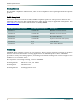
Revision History Document Revision Date Description of Changes A September 2003 Initial release B November 2004 Add STS-1; Clock Module; IP Forwarding; Service States (in TL1 Reference Guide); ±24VDC SCU; ±24VDC M13 MUX; Renumber Section 5 for growth C March 2005 Add revision details for ±24 VDC and –48 VDC modules; Update Installation Guidelines; Add Radius Documentation D October 2007 Add 1186003L3; SSH; RoHS Compliance Conventions The following typographical conventions are used in this do
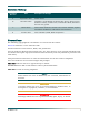
MX2820 System Manual Compliance For detailed compliance information, refer to the compliance notice packaged with the specific product. RoHS Complaint This issue of this document includes RoHS compliant products. The products listed in the following table meet the EU's RoHS Directive 2002/95/EC and/or applicable exemptions. See www.adtran.com for further information on RoHS/WEEE.
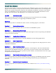
About this Manual This manual provides a complete description of the MX2820 system and system software. The purpose of this manual is to provide the technician, system administrator, and manager with general and specific information related to the planning, installation, operation, and maintenance of the MX2820 system. This manual is arranged so that needed information can be quickly and easily found. The following is an overview of the contents.
MX2820 System Manual Section 8 Trouble Analysis Procedures This section provides information to assist in locating and identifying alarm conditions.
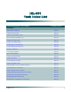
IXL-001 Task Index List Find the Required Task in the List Below: For details, refer to: Installation Shelf and SCU Installation NTP-001 Unpack and Inspect Shelf DLP-500 Mount Shelf, Heat Baffle, and Fan DLP-501 Remove and Re-install Metal Cover DLP-502 Connect Power and Ground DLP-503 Install SCU in MX2820 Shelf DLP-504 Install Modules in MX2820 Shelf DLP-505 Connect MX2820 Wire-Wrap Posts DLP-506 M13 MUX Installation NTP-002 Clock Module Installation NTP-003 STS-1 MUX Installation
MX2820 System Manual Find the Required Task in the List Below: For details, refer to: Acceptance Test MX2820 Acceptance Test Procedure DLP-601 MUX Module Acceptance Test Procedure DLP-602 STS-1 MUX Acceptance Test Procedure DLP-603 Provisioning Logging on to the System DLP-716 Set TIRKS Parameters for the SCU DLP-717 Provision Network Management Settings DLP-718 SCU Provisioning (System Management) NTP-005 Enable or Disable Smart Start DLP-729 Provision DS3/DS2 Network DLP-730 Set Date
Contents Section 1 System Description . . . . . . . . . . . . . . . . . . . . . . . . . . . . . . . . . . . . . . . . . . . . . . . . . . . . . . . . . . . . . . 1-1 Introduction . . . . . . . . . . . . . . . . . . . . . . . . . . . . . . . . . . . . . . . . . . . . . . . . . . . . . . . . . . . . . . . . . . . . . . . . . 1-3 System Overview. . . . . . . . . . . . . . . . . . . . . . . . . . . . . . . . . . . . . . . . . . . . . . . . . . . . . . . . . . . . . . . . . . . . . 1-3 Features and Benefits . .
MX2820 System Manual Alarms . . . . . . . . . . . . . . . . . . . . . . . . . . . . . . . . . . . . . . . . . . . . . . . . . . . . . . . . . . . . . . . . . . . . . . . . . . 1-20 Alarm Relay Contacts . . . . . . . . . . . . . . . . . . . . . . . . . . . . . . . . . . . . . . . . . . . . . . . . . . . . . . . . . . . 1-20 Environmental Alarm Inputs . . . . . . . . . . . . . . . . . . . . . . . . . . . . . . . . . . . . . . . . . . . . . . . . . . . . . . 1-21 Section 2 Engineering Guidelines. . . . . . .
Contents Space Considerations. . . . . . . . . . . . . . . . . . . . . . . . . . . . . . . . . . . . . . . . . . . . . . . . . . . . . . . . . . . . . . . . . Vertical and Horizontal Space Requirements . . . . . . . . . . . . . . . . . . . . . . . . . . . . . . . . . . . . . . . . . . . . . Use of Horizontal Spaces in a NEBS Lineup . . . . . . . . . . . . . . . . . . . . . . . . . . . . . . . . . . . . . . . . . . . . . Fitting the Shelf into MTU and RT Applications . . . . . . . . . . . . . . . . . . . .
MX2820 System Manual Slot #A/#B State. . . . . . . . . . . . . . . . . . . . . . . . . . . . . . . . . . . . . . . . . . . . . . . . . . . . . . . . . . . . VT/Port State . . . . . . . . . . . . . . . . . . . . . . . . . . . . . . . . . . . . . . . . . . . . . . . . . . . . . . . . . . . . . . Timing Status . . . . . . . . . . . . . . . . . . . . . . . . . . . . . . . . . . . . . . . . . . . . . . . . . . . . . . . . . . . . . . Sync Status . . . . . . . . . . . . . . . . . . . . . . . . . . . . . . . . .
Contents STS-1 PM Near-End Parameter Descriptions . . . . . . . . . . . . . . . . . . . . . . . . . . . . . . . . . . . . . STS-1 PM Far-End Parameter Descriptions . . . . . . . . . . . . . . . . . . . . . . . . . . . . . . . . . . . . . . STS-1 Alarm Condition Descriptions . . . . . . . . . . . . . . . . . . . . . . . . . . . . . . . . . . . . . . . . . . . . STS-1 Near-End Daily Thresholds and Alarms . . . . . . . . . . . . . . . . . . . . . . . . . . . . . . . . . . . .
MX2820 System Manual CSU Loopback . . . . . . . . . . . . . . . . . . . . . . . . . . . . . . . . . . . . . . . . . . . . . . . . . . . . . . . . . . . . . 5-98 CSU Loopback w/BERT. . . . . . . . . . . . . . . . . . . . . . . . . . . . . . . . . . . . . . . . . . . . . . . . . . . . . . 5-99 VT BERT . . . . . . . . . . . . . . . . . . . . . . . . . . . . . . . . . . . . . . . . . . . . . . . . . . . . . . . . . . . . . . . . . 5-99 Line BERT . . . . . . . . . . . . . . . . . . . . . . . . . . . . . . . . .
Contents SCA TFTP Server . . . . . . . . . . . . . . . . . . . . . . . . . . . . . . . . . . . . . . . . . . . . . . . . . . . . . . SCA Remote Filename . . . . . . . . . . . . . . . . . . . . . . . . . . . . . . . . . . . . . . . . . . . . . . . . . . SCA AutoSave Status . . . . . . . . . . . . . . . . . . . . . . . . . . . . . . . . . . . . . . . . . . . . . . . . . . . Perform TFTP SCA Save . . . . . . . . . . . . . . . . . . . . . . . . . . . . . . . . . . . . . . . . . . . . . . . .
MX2820 System Manual Introduction. . . . . . . . . . . . . . . . . . . . . . . . . . . . . . . . . . . . . . . . . . . . . . . . . . . . . . . . . . . . . . . . . . Save Provisioning . . . . . . . . . . . . . . . . . . . . . . . . . . . . . . . . . . . . . . . . . . . . . . . . . . . . . . . . . . . . . Restore Factory Defaults . . . . . . . . . . . . . . . . . . . . . . . . . . . . . . . . . . . . . . . . . . . . . . . . . . . . . . . Card Reset . . . . . . . . . . . . . . . . . . . . . . . . . . . . . .
Contents Prerequisite Procedures . . . . . . . . . . . . . . . . . . . . . . . . . . . . . . . . . . . . . . . . . . . . . . . . . . . . . . . . . Materials Required . . . . . . . . . . . . . . . . . . . . . . . . . . . . . . . . . . . . . . . . . . . . . . . . . . . . . . . . . . . . . Procedure . . . . . . . . . . . . . . . . . . . . . . . . . . . . . . . . . . . . . . . . . . . . . . . . . . . . . . . . . . . . . . . . . . . . Follow-up Procedures. . . . . . . . . . . . . . . . . . . . . . . . . . . . .
MX2820 System Manual Shelf with Pusher Fan Assembly . . . . . . . . . . . . . . . . . . . . . . . . . . . . . . . . . . . . . . . . . . . . . . . 7-16 Follow-up Procedures. . . . . . . . . . . . . . . . . . . . . . . . . . . . . . . . . . . . . . . . . . . . . . . . . . . . . . . . . . . 7-16 DLP-502 Remove and Re-install Metal Cover . . . . . . . . . . . . . . . . . . . . . . . . . . . . . . . . . . . . . . . . . . . . . . 7-17 Introduction . . . . . . . . . . . . . . . . . . . . . . . . . . . . . . . .
Contents Prerequisite Procedures . . . . . . . . . . . . . . . . . . . . . . . . . . . . . . . . . . . . . . . . . . . . . . . . . . . . . . . . . Tools Required . . . . . . . . . . . . . . . . . . . . . . . . . . . . . . . . . . . . . . . . . . . . . . . . . . . . . . . . . . . . . . . . Procedure . . . . . . . . . . . . . . . . . . . . . . . . . . . . . . . . . . . . . . . . . . . . . . . . . . . . . . . . . . . . . . . . . . . . Follow-up Procedures. . . . . . . . . . . . . . . . . . . . . . . . . . . .
MX2820 System Manual Introduction . . . . . . . . . . . . . . . . . . . . . . . . . . . . . . . . . . . . . . . . . . . . . . . . . . . . . . . . . . . . . . . . . . . 7-67 Prerequisite Procedures . . . . . . . . . . . . . . . . . . . . . . . . . . . . . . . . . . . . . . . . . . . . . . . . . . . . . . . . . 7-67 Tools Required . . . . . . . . . . . . . . . . . . . . . . . . . . . . . . . . . . . . . . . . . . . . . . . . . . . . . . . . . . . . . . . . 7-67 Materials Required . . . . . . . . . . . . . .
Contents Materials Required . . . . . . . . . . . . . . . . . . . . . . . . . . . . . . . . . . . . . . . . . . . . . . . . . . . . . . . . . . . . . 7-86 Procedure . . . . . . . . . . . . . . . . . . . . . . . . . . . . . . . . . . . . . . . . . . . . . . . . . . . . . . . . . . . . . . . . . . . . 7-86 DLP-718 Provision Network Management Settings . . . . . . . . . . . . . . . . . . . . . . . . . . . . . . . . . . . . . . . . . 7-89 Introduction . . . . . . . . . . . . . . . . . . . . . . . . . . . . .
MX2820 System Manual Procedure . . . . . . . . . . . . . . . . . . . . . . . . . . . . . . . . . . . . . . . . . . . . . . . . . . . . . . . . . . . . . . . . . . . 7-119 Follow-up Procedures. . . . . . . . . . . . . . . . . . . . . . . . . . . . . . . . . . . . . . . . . . . . . . . . . . . . . . . . . . 7-122 DLP-732 Provision SNMP Management Options . . . . . . . . . . . . . . . . . . . . . . . . . . . . . . . . . . . . . . . . . . 7-123 Introduction . . . . . . . . . . . . . . . . . . . . . . . . . .
Contents Prerequisite Procedures . . . . . . . . . . . . . . . . . . . . . . . . . . . . . . . . . . . . . . . . . . . . . . . . . . . . . . . . 7-155 Procedure . . . . . . . . . . . . . . . . . . . . . . . . . . . . . . . . . . . . . . . . . . . . . . . . . . . . . . . . . . . . . . . . . . . 7-155 Follow-up Procedures. . . . . . . . . . . . . . . . . . . . . . . . . . . . . . . . . . . . . . . . . . . . . . . . . . . . . . . . . . 7-157 DLP-741 Provision STS-1 Network . . . . . . . . . . . . . . . . . .
MX2820 System Manual M13 MUX Alarm Summary - 1186002Lx . . . . . . . . . . . . . . . . . . . . . . . . . . . . . . . . . . . . . . . . . . . . . 8-9 DS3 Alarms . . . . . . . . . . . . . . . . . . . . . . . . . . . . . . . . . . . . . . . . . . . . . . . . . . . . . . . . . . . . . . . 8-10 DS2 Alarms . . . . . . . . . . . . . . . . . . . . . . . . . . . . . . . . . . . . . . . . . . . . . . . . . . . . . . . . . . . . . . . 8-10 DS1 Alarms . . . . . . . . . . . . . . . . . . . . . . . . . . . . . . . . . .
Figures Figures Figure 1-1. MX2820 19-inch Shelf (Front and Rear View). . . . . . . . . . . . . . . . . . . . . . . . . . . . . . . . . . . . . . . . . 1-6 Figure 1-2. MX2820 23-inch Shelf (Front and Rear View). . . . . . . . . . . . . . . . . . . . . . . . . . . . . . . . . . . . . . . . . 1-6 Figure 1-3. MX2820 SCU Front Panel. . . . . . . . . . . . . . . . . . . . . . . . . . . . . . . . . . . . . . . . . . . . . . . . . . . . . . . . 1-7 Figure 1-4. MX2820 M13 MUX Module Front Panel . . . . . . . . . .
MX2820 System Manual Figure 5-34. Figure 5-35. Figure 5-36. Figure 5-37. Figure 5-38. Figure 5-39. Figure 5-40. Figure 5-41. Figure 5-42. Figure 5-43. Figure 5-44. Figure 5-45. Figure 5-46. Figure 5-47. Figure 5-48. Figure 5-49. Figure 5-50. Figure 5-51. Figure 5-52. Figure 5-53. Figure 5-54. Figure 5-55. Figure 5-56. Figure 5-57. Figure 5-58. Figure 5-59. Figure 5-60. Figure 5-61. Figure 5-62. Figure 5-63. Figure 5-64. Figure 5-65. Figure 5-66. Figure 5-67. Figure 5-68. Figure 5-69. Figure 5-70.
Figures Figure 5-81. Figure 5-82. Figure 5-83. Figure 5-84. Figure 5-85. Figure 5-86. Figure 5-87. Figure 5-88. Figure 5-89. Figure 5-90. Figure 5-91. Figure 5-92. Figure 5-93. Figure 5-94. Figure 5-95. Figure 5-96. Figure 5-97. Figure 5-98. Figure 5-99. Figure 5-100. Figure 5-101. Figure 5-102. Figure 5-103. Figure 5-104. Figure 5-105. Figure 5-106. Figure 5-107. Figure 5-108. Figure 7-1. Figure 7-2. Figure 7-3. Figure 7-4. Figure 7-5. Figure 7-6. Figure 7-7. Figure 7-8. Figure 7-9. Figure 7-10.
MX2820 System Manual Figure 7-20. Figure 7-21. Figure 7-22. Figure 7-23. Figure 7-24. Figure 7-25. Figure 7-26. Figure 7-27. Figure 7-28. Figure 7-29. Figure 7-30. Figure 7-31. Figure 7-32. Figure 7-33. Figure 7-34. Figure 7-35. Figure 7-36. Figure 7-37. Figure 7-38. Figure 7-39. Figure 7-40. Figure 7-41. Figure 7-42. Figure 7-43. Figure 7-44. Figure 7-45. Figure 7-46. Figure 7-47. Figure 7-48. Figure 7-49. Figure 7-50. Figure 7-51. Figure 7-52. Figure 7-53. Figure 7-54. Figure 7-55. Figure 7-56.
Figures Figure 7-67. Figure 7-68. Figure 7-69. Figure 7-70. Figure 7-71. Figure 8-1. Figure 8-2. Figure 8-3. Clock Module Main Menu . . . . . . . . . . . . . . . . . . . . . . . . . . . . . . . . . . . . . . . . . . . . . . . . . . . . . . 7-174 Clock Module Provisioning Menu . . . . . . . . . . . . . . . . . . . . . . . . . . . . . . . . . . . . . . . . . . . . . . . . 7-174 Protection Provisioning Menu . . . . . . . . . . . . . . . . . . . . . . . . . . . . . . . . . . . . . . . . . . . . . . . . . . .
MX2820 System Manual Tables Table 1-1. Table 1-2. Table 1-3. Table 1-4. Table 1-5. Table 1-6. Table 1-7. Table 1-8. Table 2-1. Table 2-2. Table 2-3. Table 2-4. Table 2-5. Table 2-6. Table 2-7. Table 2-8. Table 2-9. Table 2-10. Table 2-11. Table 2-12. Table 2-13. Table 2-14. Table 2-15. Table 2-16. Table 5-1. Table 5-2. Table 5-3. Table 5-4. Table 5-5. Table 5-6. Table 5-7. Table 5-8. Table 5-9. Table 5-10. Table 5-11. Table 5-12. Table 5-13. Table 5-14. Table 5-15. Table 5-16. Table 5-17. Table 5-18.
Tables Table 5-22. Table 5-23. Table 5-24. Table 5-25. Table 5-26. Table 5-27. Table 5-28. Table 5-29. Table 5-30. Table 5-31. Table 5-32. Table 5-33. Table 5-34. Table 5-35. Table 5-36. Table 5-37. Table 5-38. Table 5-39. Table 5-40. Table 5-41. Table 5-42. Table 7-1. Table 7-2. Table 7-3. Table 7-4. Table 7-5. Table 7-6. Table 7-7. Table 7-8. Table 8-1. Table 8-2. Table 8-3. Table 8-4. Table 8-5. Table 8-6. Table 8-7. Table 8-8. Table 8-9. Table 8-10. Table 8-11. Table 8-12. Table 8-13. Table 8-14.
MX2820 System Manual This page is intentionally blank.
Section 1 System Description This section provides a system description for network designers who are incorporating an system into their network. Contents Introduction . . . . . . . . . . . . . . . . . . . . . . . . . . . . . . . . . . . . . . . . . . . . . . . . . . . . . . . . . . . . . . . . . . . . . . . . . . . . 1-3 System Overview . . . . . . . . . . . . . . . . . . . . . . . . . . . . . . . . . . . . . . . . . . . . . . . . . . . . . . . . . . . . . . . . . . . . . . . . 1-3 Features and Benefits .
MX2820 System Manual Network Management . . . . . . . . . . . . . . . . . . . . . . . . . . . . . . . . . . . . . . . . . . . . . . . . . . . . . . . . . . . . . . RJ-45 for 10/100Base-T . . . . . . . . . . . . . . . . . . . . . . . . . . . . . . . . . . . . . . . . . . . . . . . . . . . . . . . . . . . . RS-485 . . . . . . . . . . . . . . . . . . . . . . . . . . . . . . . . . . . . . . . . . . . . . . . . . . . . . . . . . . . . . . . . . . . . . . . . . Alarms . . . . . . . . . . . . . . . . . . . . . .
Section 1, System Description - Introduction INTRODUCTION This section of the ADTRAN MX2820 System Manual is designed for use by network engineers, planners, and designers who are upgrading a communications network. It contains general information and describes system components, system connectivity, and system modules. SYSTEM OVERVIEW The ADTRAN MX2820 high-density M13/STS-1 multiplexer system offers bandwidth consolidation at a low cost in a dense rackmount chassis.
MX2820 System Manual • Local and network timing • Provides powering options for –48 VDC or ±24 VDC systems • 19-inch or 23-inch versions available • Industry-leading 10-year warranty • NEBS Level 3, UL 60950, GR-1089-CORE compliant SYSTEM COMPONENTS The MX2820 system provides the following shelf units: • 19-inch shelf (P/N 1186001L1) • 23-inch shelf (P/N 1186001L2) The MX2820 shelf can accommodate the following units: • M13 MUX module (P/N 1186002Lx) • SCU (P/N 1186003Lx) • STS-1 Clock module (P/N 1186004
Section 1, System Description - System Components MX2820 Shelf (19-inch or 23-inch) This system consists of either a 19-inch wide or 23-inch wide by 3.5-inch high (2U) shelf. The 19-inch shelf can house seven redundant pairs of M13 or STS-1 MUX modules. The 23-inch shelf can house nine redundant pairs of M13 or STS-1 MUX modules. Each M13 or STS-1 pair provides equipment protection only. Three additional slots are available to house common modules.
MX2820 System Manual MX 2820 Figure 1-1 shows the front and rear views for a MX2820 19-inch shelf.
Section 1, System Description - System Components System Modules System Controller Unit • P/N 1186003L1 for –48 VDC (revision T and earlier) • P/N 1186003L1 for –48 VDC or ±24 VDC (revision U and later) • P/N 1186003L2 for –48 VDC or ±24 VDC • P/N 1186003L5 for –48 VDC • P/N 1186003E1 for –48 VDC or ±24 VDC NOTE To determine the revision indicator, locate the sticker with the 8 or 15-character serial number and UPC label. The revision indicator is the leftmost character on that label.
MX2820 System Manual The MX2820 SCU provides the following features: • Manages RJ-45 10/100Base-T Ethernet port for SNMP, TFTP, Telnet, and SSH access • Interbank communications capability to address multiple shelves with a single IP via an RS-485 daisy chain communication link between shelves • One IP address per shelf • X.
Section 1, System Description - System Components M13 MUX Module • P/N 1186002L1 for –48 VDC (revision K and earlier) • P/N 1186002L1 for –48 VDC or ±24 VDC (revision L and later) • P/N 1186002L2 for –48 VDC or ±24 VDC • P/N 1186002L5 for –48 VDC or ±24 VDC • P/N 1186002E1 for –48 VDC or ±24 VDC The M13 MUX module acts as a multiplexer/de-multiplexer, accepting a single DS3 input signal and provides 28 DSX-1 or 21 E1 output signals and vice-versa.
MX2820 System Manual • Detects and indicates DS3 alarm and loopback conditions • Local or loop timing modes • Operates over temperature range of –40°C to +50°C (no fans), –40°C to +65°C (with fans) • Manual and remote-initiated line and terminal loopback modes • Reports alarms to SCU • Supports downloading of FLASH program data from the SCU • Front panel indication of Active, Alarm, DS3, and DS1 status • NEBS Level 3, UL60950, GR-1089-CORE compliant • Hot swappable • Derives power from redundant VDC suppli
Section 1, System Description - System Components Table 1-2.
MX2820 System Manual Clock Card • P/N 1186004L1 The MX2820 Clock Card is a plug-in card which generates a timing signal synchronized to either of two external BITS clock references. If both BITS clock references fail, the Clock Card will meet SONET Minimum Clock (SMC) holdover requirements to produce the clock reference. This signal may be used by any one of the MX2820 STS-1 MUX modules to synchronize their STS-1 transmit signals.
Section 1, System Description - System Components NOTE The MX2820 has two power options: –48VDC or ±24 VDC. The Clock Card operates at –48VDC only. Do not deploy a ±24 VDC system if Clock Cards are deployed for STS-1 MUX timing. Clock Card Front Panel LEDs Table 1-3 provides a description of the front panel LED. Table 1-3.
MX2820 System Manual STS-1 MUX • P/N 1186005L1 The MX2820 STS-1 MUX is a multiplexer unit that plugs into an MX2820 chassis. The MX2820 STS-1 MUX interfaces to a standard STS-1 signal from the network to provide 28 DSX-1 or 21 E1 outputs on the terminal side through the demapping of 28 VT1.5s or 21 VT2s. Two MX2820 MUX cards are used together to provide a redundant STS-1 multiplexer circuit. The MX2820 STS-1 MUX provides 1:1 redundancy and meets the requirements for NEBS Level 3.
Section 1, System Description - System Components STS-1 MUX Front Panel LEDs Table 1-4 provides a description of the front panel LEDs. Table 1-4.
MX2820 System Manual Table 1-4.
Section 1, System Description - System Components 19-inch Shelf The MX2820 system 19-inch shelf allows the use of the accessories shown in Table 1-6. Table 1-6.
MX2820 System Manual Table 1-8.
Section 1, System Description - System Connectivity SYSTEM CONNECTIVITY The shelf backplane contains Input/Output (I/O) connectors, control and signal routing, power input and ground, plus the interconnections between BITS clock cards, MUX cards, and the SCU. Figure 1-7 shows the MX2820 Multiplexer system with management and network interfaces. SNMP Management Station NMA Mainframe DS3 Network STS-1 Ethernet LAN Network X.
MX2820 System Manual Network Interfaces The MX2820 system demultiplexes a DS3 or STS-1 input signal into DSX-1 or E1 output signals. The MX2820 system multiplexes DSX-1 or E1 input signals into DS3 or STS-1 output signals. Each MUX module accepts a single DS3 or STS-1 input signal from the network side and provides 28 DSX-1 or 21 E1 outputs. For 1:1 redundant system, the MX2820 system provides two MUX modules for each DS3 or STS-1 signal.
Section 1, System Description - System Connectivity Environmental Alarm Inputs Wire-wrap posts provide environmental alarm inputs for ACO, AUX1, AUX2, AUX3A and AUX3B alarms. For ACO, AUX1, AUX2, and AUX3A, alarms are activated when the circuit between the connecting posts is closed (a short appears across the line). For AUX3B, an alarm is activated by a cadenced input across the input posts; this input can be used to indicate a fan failure.
MX2820 System Manual This page is intentionally blank.
Section 2 Engineering Guidelines This section provides Engineering guidelines for network designers who are incorporating an system into their network. Contents Dimensions of Equipment. . . . . . . . . . . . . . . . . . . . . . . . . . . . . . . . . . . . . . . . . . . . . . . . . . . . . . . . . . . . . . . . . 2-3 System Power Requirements . . . . . . . . . . . . . . . . . . . . . . . . . . . . . . . . . . . . . . . . . . . . . . . . . . . . . . . . . . . . . . 2-4 M13 and STS-1 System Configurations . .
MX2820 System Manual Tables Table 2-1. Table 2-2. Table 2-3. Table 2-4. Table 2-5. Table 2-6. Table 2-7. Table 2-8. Table 2-9. Table 2-10. Table 2-11. Table 2-12. Table 2-13. Table 2-14. Table 2-15. Table 2-16. 2-2 MX2820 Equipment Dimensions and Weights . . . . . . . . . . . . . . . . . . . . . . . . . . . . . . . . . . . . . . . . 2-3 Current Draw of Each Module at –48 VDC . . . . . . . . . . . . . . . . . . . . . . . . . . . . . . . . . . . . . . . . . . . 2-4 Current Draw of Each Module at ±24 VDC .
Section 2, Engineering Guidelines - Dimensions of Equipment DIMENSIONS OF EQUIPMENT Table 2-1 provides the dimensions of the MX2820 chassis, heat baffles, fan, and system modules. Table 2-1. MX2820 Equipment Dimensions and Weights Part Number Equipment (H x W x D) Weight 3.50” × 17.10” × 13.50” 10.25 lb. 3.50” × 21.22" × 13.50” 12.04 lb.
MX2820 System Manual SYSTEM POWER REQUIREMENTS NOTE Refer to “Section 1, System Description” for voltage requirements of modules within each List series. Table 2-2 provides the current draw of each module at –48 VDC. For the M13 and STS-1 modules, this measurement was made with all T1s enabled and configured for maximum line length. A QRSS data pattern was utilized. Table 2-2.
Section 2, Engineering Guidelines - System Power Requirements M13 and STS-1 System Configurations Table 2-4 provides the current draw for a fully loaded M13 system at –48 VDC for a single 19inch shelf and a single 23-inch shelf deployment. Table 2-4. Current Draw at –48 VDC for fully loaded M13 System Part Number Description Quantity Current Draw Quantity times Draw Total Draw 1 68 mA 1 × 68 mA 68 mA 7 redundant pairs 340 mA 7 × 340 mA 2.
MX2820 System Manual Table 2-6 provides the current draw for a fully loaded STS-1 system at –48 VDC for a single 19-inch shelf and a single 23-inch shelf deployment. Table 2-6. Current Draw at –48 VDC for fully loaded STS-1 system Part Number Description Quantity Current Draw Quantity times Draw Total Draw 19-inch shelf 1186003Lx SCU 1 68 mA 1 × 68 mA 68 mA 1186004L1 Clock Module 2 52 mA 2 × 52 mA 104 mA 1186005L1 STS-1 MUX 7 redundant pairs 332 mA 7 × 332 mA 2.
Section 2, Engineering Guidelines - Power Dissipation Considerations POWER DISSIPATION CONSIDERATIONS Power Dissipation for an MX2820 Shelf Table 2-8 provides the heat dissipation data for each module at –48 VDC. Table 2-8. Module Heat Dissipation at –48 VDC Part Number Description Heat Dissipation Common Modules 1186003Lx SCU 3.26 W 1186004L1 Clock Module 2.50 W Multiplexer Modules 1186002Lx M13 MUX (redundant pair) 16.32 W 1186005L1 STS-1 MUX (redundant pair) 15.
MX2820 System Manual Table 2-10 provides the heat dissipation for a fully loaded M13 system at ±24 VDC for a single 19-inch shelf and a single 23-inch shelf deployment. Table 2-10. Heat Dissipation for Fully Loaded M13 System at ±24 VDC Part Number Description Quantity Heat Dissipation Watts Quantity times Watts Total Watts 1 3.12 W 1 x 3.12 W 3.12 W 7 redundant pairs 17.28 W each 7 x 17.28 W 120.96 W 19-inch shelf 1186003Lx SCU 1186002Lx M13 MUX Total watts 124.
Section 2, Engineering Guidelines - Power Dissipation Considerations Configuration Guidelines for the MX2820 System MX2820 systems can be actively cooled with fans or passively cooled by appropriately spacing shelves and incorporating baffles into the bay design. For maximum density, fans are recommended for the MX2820 system.
MX2820 System Manual • Passively cooled: – Working from the bottom of the bay, leave a 1U space between the bottom of the rack and the first shelf, install a MX2820 shelf (P/N 1186001L2). – Leave a 1U space, install a 1U passive heat baffle (P/N 1180002L1). – Leave an additional 2U space, (4U total between shelves), and install another MX2820 shelf. – Repeat these steps to fill the bay leaving a 2U space above the top-most shelf. – Figure 2-2 provides an example.
Section 2, Engineering Guidelines - Power Dissipation Considerations MX2820 Heat Dissipation and GR-63-CORE The following guidelines are intended to aid the designer and planner for installations of shelves and meeting NEBS heat release objectives. Since the system supports M13 and STS1 modules, much forethought should be given to the installation and possible future expansion. Depending on the technology employed, various scenarios and shelf densities can be achieved.
MX2820 System Manual Actively Cooled Figure 2-1 provides an example of an actively cooled bay installation that contains multiple MX2820 shelves and also meets the NEBS heat release objectives. Based on 30-inch maintenance and 24-inch wiring aisles, 12-inch equipment depth, 5-inch rack extenders, and 26inch overall equipment width, this example allows for a NEBS heat budget of 1521 watts. Nine 23-inch MX2820 shelves are shown in the bay configuration example.
Section 2, Engineering Guidelines - Power Dissipation Considerations 1U Fuse Panel 4-inch Fan and Baffle 2U MX2820 Shelf 2U MX2820 Shelf 2U MX2820 Shelf 4-inch Fan, Baffle & Filter 2U MX2820 Shelf 2U MX2820 Shelf 2U MX2820 Shelf 4-inch Fan, Baffle & Filter 2U MX2820 Shelf 2U MX2820 Shelf 2U MX2820 Shelf 4-inch Baffle & Filter Figure 2-1.
MX2820 System Manual Fuse Panel 1U Fuse Panel 43 41 39 2U MX2820 Shelf 2U Space 37 35 33 31 29 27 25 23 21 19 17 15 1U Heat Baffle 1U Space 2U MX2820 Shelf 2U Space 1U Heat Baffle 1U Space 2U MX2820 Shelf 2U Space 1U Heat Baffle 1U Space 2U MX2820 Shelf 2U Space 1U Heat Baffle 1U Space 2U MX2820 Shelf 2U Space 13 11 9 1U Heat Baffle 1U Space 2U MX2820 Shelf 2U Space 7 5 3 1U Heat Baffle 1U Space 2U MX2820 Shelf 1U Figure 2-2.
Section 2, Engineering Guidelines - Power Dissipation Considerations Other Equipment MX2820 Shelf Pusher Fan Assembly 2U MX2820 Shelf 1U Pusher Fan Assembly Other Equipment Figure 2-3.
MX2820 System Manual MANAGEMENT INTERFACES Telnet, SNMP, TFTP, and SSH over 10/100Base-T An RJ-45 connector on the backplane of an MX2820 shelf provides a 10/100Base-T Ethernet interface for the MX2820 system. Through this interface the system connects to an Internet Protocol (IP)/Local Area Network (LAN) host computer. Each MX2820 shelf requires one IP address, which can be provisioned with an MX2820 menu option. The SCU manages the Ethernet interface for the MX2820 system.
Section 2, Engineering Guidelines - DSX-1 Connections DSX-1 CONNECTIONS The DSX-1 (T1/E1) circuits provide connections to DSX-1 cross connects and to other equipment based on how the circuits are to be used for an application. Table 2-14 provides information that can be used as a guideline when wiring the FutureBusto-Stub cable. Table 2-14.
MX2820 System Manual Table 2-15 provides information for the amphenol connector pinout for the FutureBus-toamphenol cable assemblies. Table 2-15.
Section 2, Engineering Guidelines - DSX-1 Connections The information in Figure 2-4 and Table 2-16 may be used to cross-reference the wire color information in Table 2-14 with the pins of the FutureBus connector. 12 11 10 9 8 7 6 5 4 3 2 1 E D C B A Figure 2-4. FutureBus-to-Stub Cable Connector Table 2-16.
MX2820 System Manual This page is intentionally blank.
Section 3 Application Guidelines This section provides application guidelines for network designers who are incorporating a system into their network. Contents APP-301 Standard DS3-Fed System Application . . . . . . . . . . . . . . . . . . . . . . . . . . . . . . . . . . . . . . . . . . . . Usage . . . . . . . . . . . . . . . . . . . . . . . . . . . . . . . . . . . . . . . . . . . . . . . . . . . . . . . . . . . . . . . . . . . . . . . . DS3 Interface . . . . . . . . . . . . . . . . . . . . . . . . . . .
MX2820 System Manual 3-2 61186003L1-1D
APP-301 Standard DS3-Fed System Application USAGE The standard DS3-Fed application for the MX2820 system allows the M13 Multiplexer (MUX) module to accept a single DS3 input signal from the network and provide twenty-eight T1 or twenty-one E1 output signals (or a combination thereof as allowed by DS2 framing) on the terminal (customer) side. With a 1:1 redundant configuration, two M13 MUX modules can accept a single DS3 signal from the network.
MX2820 System Manual This page is intentionally blank.
APP-302 Standard DS3-Fed System Application USAGE The standard STS-1-Fed application for the MX2820 system allows the STS-1 Multiplexer (MUX) module to accept a single STS-1 input signal from the network and provide twentyeight T1 or twenty-one E1 output signals on the terminal (customer) side. With a 1:1 redundant configuration, two STS-1 MUX modules can accept a single STS-1 signal from the network.
MX2820 System Manual This page is intentionally blank.
Section 4 Site Preparation This section provides Site Preparation guidelines for network designers who are incorporating an system into their network. Contents Introduction . . . . . . . . . . . . . . . . . . . . . . . . . . . . . . . . . . . . . . . . . . . . . . . . . . . . . . . . . . . . . . . . . . . . . . . . . . . . 4-2 Prerequisite Procedures . . . . . . . . . . . . . . . . . . . . . . . . . . . . . . . . . . . . . . . . . . . . . . . . . . . . . . . . . . . . . . . . . . 4-2 Space Considerations .
MX2820 System Manual INTRODUCTION This section of the system manual provides details on how to prepare a Central Office (CO), Multi-Tenant Unit (MTU), or Remote Terminal (RT) to accept the installation of one or more MX2820 shelves. Shelves that are installed in the same bay or in adjacent bays should be engineered together so that they share common feeds for power, timing, and management interfaces as appropriate for the application.
Section 4, Site Preparation - Electrical Considerations ELECTRICAL CONSIDERATIONS The MX2820 shelf supports dual-feed –48 VDC or ±24 VDC power inputs. Power Wiring and Fusing MX2820 power connections, including return connections, should be provided from the fuse panel using insulated wire and the appropriate fuse (see Table 2-7 on page 2-6). Per application requirements, power can be provided by a –48 VDC or ±24 VDC supply.
MX2820 System Manual This page is intentionally blank.
Section 5 User Interface Guide This section provides guidelines for network designers who are incorporating a system into their networks. Contents UIG-500 MX2820 Menu Tree . . . . . . . . . . . . . . . . . . . . . . . . . . . . . . . . . . . . . . . . . . . . . . . . . . . . . . . . . . . Introduction. . . . . . . . . . . . . . . . . . . . . . . . . . . . . . . . . . . . . . . . . . . . . . . . . . . . . . . . . . . . . . . . . . . MX2820 Main Menu . . . . . . . . . . . . . . . . . . . . . . . . . . . . .
MX2820 System Manual Alarm . . . . . . . . . . . . . . . . . . . . . . . . . . . . . . . . . . . . . . . . . . . . . . . . . . . . . . . . . . . . . . . . . Protection . . . . . . . . . . . . . . . . . . . . . . . . . . . . . . . . . . . . . . . . . . . . . . . . . . . . . . . . . . . . . Card Comm . . . . . . . . . . . . . . . . . . . . . . . . . . . . . . . . . . . . . . . . . . . . . . . . . . . . . . . . . . . . Slot #A/#B State. . . . . . . . . . . . . . . . . . . . . . . . . . . . . . . . . . . . . .
Section 5, User Interface Guide STS-1 Near-End Quarter Hourly Statistics. . . . . . . . . . . . . . . . . . . . . . . . . . . . . . . . . . . . . . . . STS-1 Far-End Daily Statistics. . . . . . . . . . . . . . . . . . . . . . . . . . . . . . . . . . . . . . . . . . . . . . . . . STS-1 Far-End Quarter Hourly Statistics . . . . . . . . . . . . . . . . . . . . . . . . . . . . . . . . . . . . . . . . . STS-1 PM Near-End Parameter Descriptions . . . . . . . . . . . . . . . . . . . . . . . . . . . . . . . . . .
MX2820 System Manual UIG-540 5-4 Digital Line/Net. . . . . . . . . . . . . . . . . . . . . . . . . . . . . . . . . . . . . . . . . . . . . . . . . . . . . . . . . . . . CODEC Line/Net . . . . . . . . . . . . . . . . . . . . . . . . . . . . . . . . . . . . . . . . . . . . . . . . . . . . . . . . . . CSU Loopback . . . . . . . . . . . . . . . . . . . . . . . . . . . . . . . . . . . . . . . . . . . . . . . . . . . . . . . . . . . . CSU Loopback w/BERT. . . . . . . . . . . . . . . . . . . . . . . . . . . . .
Section 5, User Interface Guide Restore Provisions to Modules . . . . . . . . . . . . . . . . . . . . . . . . . . . . . . . . . . . . . . . . . . . . Hot Keys . . . . . . . . . . . . . . . . . . . . . . . . . . . . . . . . . . . . . . . . . . . . . . . . . . . . . . . . . . . . . SCA Operations Screen. . . . . . . . . . . . . . . . . . . . . . . . . . . . . . . . . . . . . . . . . . . . . . . . . . . . . SCA TFTP Server . . . . . . . . . . . . . . . . . . . . . . . . . . . . . . . . . . . . . . . . . . . .
MX2820 System Manual MIB . . . . . . . . . . . . . . . . . . . . . . . . . . . . . . . . . . . . . . . . . . . . . . . . . . . . . . . . . . . . . . . . . 5-141 adGenSlotAddress and adGenPortAddress mapping. . . . . . . . . . . . . . . . . . . . . . . . 5-142 UIG-550 Access Module Utilities . . . . . . . . . . . . . . . . . . . . . . . . . . . . . . . . . . . . . . . . . . . . . . . . . . . . . . Introduction. . . . . . . . . . . . . . . . . . . . . . . . . . . . . . . . . . . . . . . . . . . . . . . . .
Section 5, User Interface Guide Figure 5-28. Figure 5-29. Figure 5-30. Figure 5-31. Figure 5-32. Figure 5-33. Figure 5-34. Figure 5-35. Figure 5-36. Figure 5-37. Figure 5-38. Figure 5-39. Figure 5-40. Figure 5-41. Figure 5-42. Figure 5-43. Figure 5-44. Figure 5-45. Figure 5-46. Figure 5-47. Figure 5-48. Figure 5-49. Figure 5-50. Figure 5-51. Figure 5-52. Figure 5-53. Figure 5-54. Figure 5-55. Figure 5-56. Figure 5-57. Figure 5-58. Figure 5-59. Figure 5-60. Figure 5-61. Figure 5-62. Figure 5-63.
MX2820 System Manual Figure 5-75. Figure 5-76. Figure 5-77. Figure 5-78. Figure 5-79. Figure 5-80. Figure 5-81. Figure 5-82. Figure 5-83. Figure 5-84. Figure 5-85. Figure 5-86. Figure 5-87. Figure 5-88. Figure 5-89. Figure 5-90. Figure 5-91. Figure 5-92. Figure 5-93. Figure 5-94. Figure 5-95. Figure 5-96. Figure 5-97. Figure 5-98. Figure 5-99. Figure 5-100. Figure 5-101. Figure 5-102. Figure 5-103. Figure 5-104. Figure 5-105. Figure 5-106. Restore Default Provisioning Screen . . . . . . . . . . . . . . .
Section 5, User Interface Guide Table 5-13. Table 5-14. Table 5-15. Table 5-16. Table 5-17. Table 5-18. Table 5-19. Table 5-20. Table 5-21. Table 5-22. Table 5-23. Table 5-24. Table 5-25. Table 5-26. Table 5-27. Table 5-28. Table 5-29. Table 5-30. Table 5-31. Table 5-32. Table 5-33. Table 5-34. Table 5-35. Table 5-36. Table 5-37. Table 5-38. Table 5-39. Table 5-40. STS-1 MUX Alarm Conditions. . . . . . . . . . . . . . . . . . . . . . . . . . . . . . . . . . . . . . . . . . . . . . . . . . . .
MX2820 System Manual This page is intentionally blank.
UIG-500 MX2820 Menu Tree INTRODUCTION This subsection provides the menu trees for the MX2820 system. NOTE Menu trees in this manual are representative of the List 1 and List 2 modules. Other List series are available. Refer to the Job Aid shipped with those modules for their menu trees.
MX2820 System Manual MX2820 MAIN MENU Figure 5-1 shows the Main Menu screen for the MX2820 system. User-interface tasks are initiated from the Main Menu. “Section 6, Non-Trouble Clearing Procedures” lists the provisioning tasks for the Network (DS3/STS-1) interface, DSX-1 (T1/E1) interface, and the SCU. “Section 7, Detailed Level Procedures” provides detailed procedural steps for the tasks listed in “Section 6”.
Section 5, User Interface Guide - UIG-500, MX2820 Menu Tree SCU MENU TREE Figure 5-2 shows the menu tree for the MX2820 System Controller Unit (SCU). 1. 9600* Unit Name CLEI Code 1. Configuration 2. 19200 1. Craft Port Baud Rate Part Number 3. 38400 Serial Number 4. 57600 5. 115200 Product Revision Software Revision 1. Management Ports Boot ROM Version MAC Address HOST 2. Interbank Comm. Mode 2. Date Auto-Logoff 3. Time 1. Change Password/Access Privilege 2.
MX2820 System Manual M13 MUX MENU TREE Figure 5-3 shows the menu tree for the MX2820 M13 Multiplexer (MUX) module. CLEI Code 1. Configuration Part Number Serial Number Code Version Code Checksum Boot Version Boot Checksum Self Test 1. DS3 Framing 1. Network Interface 1. C-BIT 1. Loop 2. M13* 2. Local* 2. DS3 Timing 1. Disabled 1. Disabled* 2. FEAC/C-BIT* 3. FEAC 3. DS3 Remote Loopbacks 2. 1E-3 3. 1E-4 4. C-BIT 4. 1E-5 5. 1E-6 4. DS3 XCV Threshold 5. IP Forwarding Protocol 1.
Section 5, User Interface Guide - UIG-500, MX2820 Menu Tree STS-1 MUX MENU TREE Figure 5-4 shows the menu tree for the MX2820 STS-1 MUX module. 1. Loop 2. Free-Run 3. External 1. Network Timing 2. VT Mode CLEI Code To/from SCU menus 1. Configuration Part Number Serial Number 1. 2 seconds* 1. Transmitted Received 2. Expected 3. Set Expected Equal to Received 1. VT1.5 (T1) 2. VT2 (E1) 1. Network Interface 3. STS-1 J1 Path Trace Code Version Code Checksum Boot Version Boot Checksum Self Test 29.
MX2820 System Manual CLOCK MODULE MENU TREE Figure 5-5 shows the menu tree for the MX2820 Clock Module. CLEI Code 1. Configuration Part Number Serial Number Code Version Code Checksum Boot Version Boot Checksum Self Test 1. Timing Mode 1. Clock Interface 2. Timing Type 3. Termination 1. External Timing* 2. Force Hold Over 1. SF/ESF* 2. All Ones 1. Disabled 2. Enabled* 2. Provisioning 1. Card CLK A Equipment Provisioned State Card CLK A Equipment Functional State 2. Service States 2.
UIG-510 Status INTRODUCTION This subsection provides the instructions for viewing the status of the following items: • Shelf alarms • SCU module alarms • M13 MUX module alarms • STS-1 MUX module alarms • Clock Module alarms 61186003L1-1D 5-17
MX2820 System Manual SHELF ALARMS View the status of shelf alarms by selecting the following options: • Select SYSTEM ALARMS, from the MX2820 Main Menu, and press ENTER. • Select SHELF ALARM STATUS, from the System Alarms menu, and press ENTER. • Return to the MX2820 Main Menu by pressing ESC until the menu appears. Figure 5-6 shows an example of the Shelf Alarm screen for a 19-inch shelf. Menu selections are as follows: • M displays the Master alarm log. • S displays the SCU alarm log.
Section 5, User Interface Guide - UIG-510, Status SCU ALARMS View the status of SCU alarms by selecting the following options: • Select SYSTEM CONTROLLER, from the MX2820 Main Menu, and press ENTER. • Select STATUS, from the System Controller menu, and press ENTER. • Return to the MX2820 Main Menu, by pressing ESC until the menu appears. Figure 5-7 shows the SCU Status screen. The following subsection describes the fields in the External Inputs section.
MX2820 System Manual Table 5-1. SCU Alarm Status Screen, External Inputs (Continued) Input Name Severity Description AUX #3B User Definable When acting as a fan alarm, this input will generate a cadenced alarm signal which indicates a partial failure of the fan module. PWR Bus A User Definable This input generates an alarm signal when one of the power supplies fails. When both power supplies fail, a critical alarm will be generated to indicate a complete power failure at the SCU.
Section 5, User Interface Guide - UIG-510, Status DS3 State State This field displays the current state of the DS3 network for the specified M13 MUX module. Table 5-2 lists the possible conditions. Table 5-2. DS3 State Conditions Condition Description Normal The MX2820 (M13 MUX module) is ready to pass data. Alarm The unit is currently receiving an alarm condition. Table 5-3 lists the alarms. Test The unit is currently in test mode. Alarm/Test The unit is in an alarm condition and in test mode.
MX2820 System Manual Rx Framing This field shows the network framing type (C-Bit or M13). Remote This field indicates the current state of the remote MX2820 system or terminal equipment (available with C-Bit framing only). Table 5-4 list the possible conditions. Table 5-4. Remote System (Terminal) Conditions Condition Description Normal The far-end MX2820 system is not reporting any conditions. RAI The far-end unit is receiving an Remote Alarm Indication (RAI) (yellow) alarm from the network.
Section 5, User Interface Guide - UIG-510, Status Multiplexer State Alarm This field displays the current alarm condition for the Multiplexer State. Table 5-5 lists the possible alarm conditions. Table 5-5. Multiplexer Alarm Conditions Alarm (Condition) Description None No multiplexer state alarms. Excessive Switches This condition indicates the maximum switching threshold has been exceeded. Switched to Protect This condition indicates a module switch has occurred.
MX2820 System Manual Slot #A/#B State This field indicates the current status of the two MUX modules. Table 5-8 provides the possible states. Table 5-8. M13 MUX Slot A/B State State Description Not Installed A MUX module is not installed in this slot. Standby The MUX module is ready to pass data, but is currently acting as a backup module. Active The MUX module is acting as the primary module. DS2 State This field indicates the current state of the seven DS2s.
Section 5, User Interface Guide - UIG-510, Status T1/E1 State This field indicates the current state of the individual T1s or E1s. Table 5-10 provides the possible state conditions. A DS2 can be divided into three E1s or four T1s. Therefore, some of the fields in the T1/E1 State menus do not apply for an E1 configuration. Table 5-10. T1/E1 State Conditions Condition Description OK The T1/E1 is ready to pass data. OFF The T1/E1 is configured for disable. AUTO The T1/E1 is configured for Auto-Enable.
MX2820 System Manual STS-1 MUX MODULE View the status of an STS-1 MUX module by selecting the following options and selecting the number for a slot location: • Select ACCESS MODULES, from the MX2820 Main Menu, and press ENTER. • Select a number from 1 to 7 (19-inch shelf) or 1 to 9 (23-inch shelf), corresponding to the desired STS-1 MUX Module, from the Access Module Menus screen, and press ENTER. • Select STATUS. Figure 5-9 shows an example of the status for an STS-1 module in slot location 4.
Section 5, User Interface Guide - UIG-510, Status STS-1 State State This field displays the current state of the STS-1 network for the specified STS-1 MUX module. Table 5-11 lists the possible conditions. Table 5-11. STS-1 State Conditions Condition Description Normal The MX2820 (STS-1 MUX module) is ready to pass data. Alarm The unit is currently receiving an alarm condition. Table 5-12 lists the alarms. Test The unit is currently in test mode.
MX2820 System Manual Table 5-12. STS-1 Alarm Condition Descriptions (Continued) STS-1 Alarm Definition Condition Description RFI-P Remote Failure Indication - Path The unit is receiving a line remote failure indication (RFI-P is declared when the incoming path remote defect indication [RDI-P, “1” in bit 5 of the G1 path overhead byte for contiguous frames] lasts for 2.5 ±0.5 seconds.
Section 5, User Interface Guide - UIG-510, Status Card Comm This field indicates the current state of the communication link between the two STS-1 MUX modules. Table 5-15 provides the possible conditions. Table 5-15. STS-1 MUX Card Communication State State Description OK This condition indicates the modules are communicating. Failure This condition indicates the modules are not able to communicate with each other. Non-Redundant This condition indicates only one module is installed.
MX2820 System Manual Table 5-17. VT/Port Alarm Condition Descriptions (Continued) VT/Port Alarm Definition Condition Description LOP VT Path Loss of Pointer A VT LOP defect is declared when either a valid pointer is not detected in eight consecutive VT superframes, or when eight consecutive VT superframes are detected with the NDF set to “1001” without a valid concatenation indicator. A VT LOP is declared when the VT LOP defect persists for 2.5 ±0.5 seconds.
Section 5, User Interface Guide - UIG-510, Status A Detailed VT/Port Status screen is available from the STS-1 Status screen. Type the numeral 1 in the field labeled SELECTION and press ENTER. The screen is illustrated in Figure 5-10.
MX2820 System Manual Sync Status Synchronization Status Messages (Table 5-20) provided in the S1 byte can provide the following benefits: • Automatic reconfiguration of line-timed rings • Improved reliability of interoffice timing distribution • Troubleshooting of synchronization-related messages Table 5-20.
Section 5, User Interface Guide - UIG-510, Status MX2820 CLOCK MODULE View the status of an MX2820 Clock module by selecting the following options and selecting the number for a slot location: • Select ACCESS MODULES, from the MX2820 System menu, and press ENTER. • Type the letter C, corresponding to SMC (clock) and press ENTER. • Select STATUS. Figure 5-11 shows an example of the Status screen for a Clock module in slot location A.
MX2820 System Manual Clock Reference This field indicates which clock input is currently being used to derive timing. Table 5-22 lists the possible indications. Table 5-22. Clock Reference Indications Indications Description Primary Clock input A is being used to derive timing. Secondary Clock input B is being used to derive timing. PRI Clock Status This field displays the current status of the primary clock reference. Table 5-13 lists the possible conditions. Table 5-23.
Section 5, User Interface Guide - UIG-510, Status Clock State This field indicates the current state of the Clock synchronization circuitry. Table 5-25 provides the possible conditions. Table 5-25. MX2820 Clock State State Description Reset The clock synchronization circuitry is being initialized. Norm The clock synchronization circuitry is synchronized to the indicated external clock reference. Hold-over The clock circuitry is locked and no longer tracking the external clock reference.
MX2820 System Manual Protection This field indicates the current protection mode for the Clock module. Table 5-27 provides the possible state conditions. Table 5-27. Clock Module Protection Modes Mode Description Circuit The unit is in Circuit Protection mode and everything is functioning. None One Clock Module is installed, or the unit is in Circuit Protection mode, and the secondary card has failed.
UIG-520 M13 MUX PM Statistics INTRODUCTION This subsection provides the instructions to access Performance Monitoring (PM) screens to allow the following: • Viewing PM statistics for the near-end of the DS3 network • Viewing PM statistics for the far-end of the DS3 network • Viewing PM statistics for the individual T1/E1 circuits • Setting PM threshold levels • Enabling or disabling threshold alarms These functions are performed from the DS3 Statistics screen.
MX2820 System Manual Shelf: 1 Slot: 4A Unacknowledged Alarms: None ADTRAN MX2820 System TID: 04/15/04 02:44 HTVLALEXD16 Performance Monitoring 1 - DS3 Statistics 2 - T1/E1 Statistics 3 - Clear ALL Statistics Selection: '?' - System Help Screen Figure 5-12.
Section 5, User Interface Guide - UIG-520, M13 MUX PM Statistics VIEWING DS3 PM STATISTICS To view DS3 PM statistics, perform the following steps on each screen: 1. Select the desired option, by number, from the menu and then press ENTER. 2. Return to a previous screen by pressing ESC until the desired screen appears. The timeframe and direction are selected from this screen. Examples of the DS3 PM Statistics screens are shown in the following section.
MX2820 System Manual DS3 Near-End Quarter Hourly Statistics DS3 near-end quarter-hourly statistics are maintained for the current 15-minute interval and the completed 96 previous 15-minute intervals (providing a 24-hour history). A total is also provided that represents the sum of the previous 96 15-minute intervals. Figure 5-15 shows an example of the DS3 Near-End Quarter Hourly screen.
Section 5, User Interface Guide - UIG-520, M13 MUX PM Statistics DS3 Far-End Daily Statistics DS3 far-end daily statistics are maintained for the current 24-hour period and the seven previous days. Figure 5-16 shows an example of the DS3 Far-End Daily screen. NOTE These statistics do not apply if the DS3 Framing is set to M13.
MX2820 System Manual DS3 Far-End Quarter Hourly Statistics DS3 far-end quarter-hourly statistics are maintained for the current 15-minute interval and the completed 96 previous 15-minute intervals (providing a 24-hour history). A total is also provided that represents the sum of the previous 96 15-minute intervals. Figure 5-15 shows an example of the DS3 Far-End Quarter Hourly screen. NOTE These statistics do not apply if the DS3 Framing is set to M13.
Section 5, User Interface Guide - UIG-520, M13 MUX PM Statistics DS3 PM Near-End Parameter Descriptions Table 5-30 provides DS3 PM near-end parameter descriptions. Table 5-30. DS3 PM Near-End Parameter Descriptions DS3 PM Parameter Definition Description CV-L Code Violation Line This parameter indicates the number of Bipolar Violations (BPVs) and Excessive Zeros (EXZs) that have occurred.
MX2820 System Manual Table 5-30. DS3 PM Near-End Parameter Descriptions (Continued) DS3 PM Parameter Definition Description SESCP-P Severely Errored Second, CP-Bit Parity - Path This parameter indicates the number of seconds with 45 or more CP-Bit parity errors, one or more SEF defects, or one or more AIS defects. This count is not incremented when UAS are counted. UASCP-P Unavailable Second, CP-Bit Parity Path This parameter indicates the number of seconds that the DS3 path is unavailable.
Section 5, User Interface Guide - UIG-520, M13 MUX PM Statistics DS3 PM Far-End Parameter Descriptions Table 5-31 provides DS3 PM far-end parameter descriptions that apply to C-Bit Framing only. Table 5-31. DS3 PM Far-End Parameter Descriptions (C-Bit Framing Only) DS3 PM Parameter Definition Description CVCP-PFE Code Violation, CPBit Parity - Path This parameter indicates the number of CP-Bit parity errors that have occurred. This count is not incremented when UAS are counted.
MX2820 System Manual SETTING DS3 THRESHOLDS AND ENABLING ALARMS Set the thresholds and enable or disable associated alarms from the DS3 Statistics screen. DS3 Near-End Daily Thresholds and Alarms To set a DS3 Near-End Daily threshold level and alarm, select NEAR END DAILY THRESHOLDS, by number, from the menu and then press ENTER. Figure 5-18 shows an example of the Near-End Daily Thresholds menu screen.
Section 5, User Interface Guide - UIG-520, M13 MUX PM Statistics DS3 Near-End Quarter Hourly Thresholds and Alarms Select NEAR END QUARTER HOURLY THRESHOLDS from the DS3 Statistics menu screen, and press ENTER. Figure 5-19 shows an example of the Near End Quarter Hourly Thresholds menu screen.
MX2820 System Manual DS3 Far-End Daily Thresholds and Alarms Select FAR END DAILY THRESHOLDS from the DS3 Statistics menu screen, and press ENTER. Figure 5-20 shows an example of the Far-End Daily Thresholds menu screen.
Section 5, User Interface Guide - UIG-520, M13 MUX PM Statistics DS3 Far-End Quarter Hourly Thresholds and Alarms Select FAR END QUARTER HOURLY THRESHOLDS from the DS3 Statistics menu screen. Figure 5-21 shows an example of the Far-End Quarter Hourly Thresholds menu screen.
MX2820 System Manual VIEWING T1/E1 PM STATISTICS To access the T1/E1 Statistics screen, select the options from each screen listed and then press ENTER: 1. Select ACCESS MODULES from the MX2820 Main Menu. 2. Select a number from 1 to 7 for a 19-inch shelf or 1 to 9 for a 23-inch shelf, from the Access Module Menus, and press ENTER. 3. Select PERFORMANCE MONITORING from the Access Module Main Menu. 4. Select T1/E1 STATISTICS from the Performance Monitoring menu.
Section 5, User Interface Guide - UIG-520, M13 MUX PM Statistics T1/E1 Near-End Daily Statistics NOTE T1/E1 near-end daily statistics are maintained for the current 24hour period and the seven previous days. Select NEAR END DAILY from the T1/E1 Statistics screen. Each T1/E1 line displays either CLEAR or PM DATA. CLEAR indicates all PM statistics for that T1/ E1 line are zero. PM DATA indicates PM statistics for that T1/E1 line are non-zero. The menu screen for the T1/E1 circuits appears.
MX2820 System Manual Shelf: 1 Slot: 4A Unacknowledged Alarms: None ADTRAN MX2820 System TID: 04/15/04 02:44 HTVLALEXD16 T1/E1 Statistics - Near End Daily T1 #1 CV-L ES-L SES-L LOSS-L Current 0 0 0 0 09/16 0 0 0 0 09/15 0 0 0 0 09/14 N/A N/A N/A N/A 09/13 N/A N/A N/A N/A 09/12 N/A N/A N/A N/A 09/11 N/A N/A N/A N/A 09/10 N/A N/A N/A N/A AISS-P 0 0 0 N/A N/A N/A N/A N/A '?' - System Help Screen Figure 5-24.
Section 5, User Interface Guide - UIG-520, M13 MUX PM Statistics T1/E1 Near-End Quarter Hourly Statistics NOTE T1/E1 near-end quarter-hourly statistics are maintained for the current 15-minute interval and the completed 96 previous 15-minute intervals (providing a 24-hour history). A total is also provided that represents the sum of the previous 96 15-minute intervals. Select NEAR END QUARTER HOURLY from the T1/E1 Statistics screen, and select a desired T1/E1 circuit.
MX2820 System Manual Shelf: 1 Slot: 4A Unacknowledged Alarms: None ADTRAN MX2820 System TID: 04/15/04 02:44 HTVLALEXD16 T1/E1 Statistics - Near End Quarter Hourly T1 #1 - AUTO (Unframed) Current 0 0 0 0 Total 0 0 0 0 19:45 0 0 0 0 19:30 0 0 0 0 19:15 0 0 0 0 19:00 0 0 0 0 18:45 0 0 0 0 18:30 0 0 0 0 CV-P ES-P SES-P UAS-P 0 0 0 0 0 0 0 0 0 0 0 0 0 0 0 0 0 0 0 0 0 0 0 0 0 0 0 0 0 0 0 0 AISS-P 0 0 0 0 0 0 0 0 CV-L ES-L SES-L LOSS-L Select Interval: (B) to go Back.
Section 5, User Interface Guide - UIG-520, M13 MUX PM Statistics Table 5-32. T1/E1 PM Parameter Descriptions (Continued) T1/E1 PM Parameter Definition Description For P/N 1186002L3 Only: CV-P Code Violation Path SF Mode: This parameter indicates the number of frame synchronization bit errors that have occurred during the accumulation period. ESF Mode: This parameter indicates the number of CRC-6 errors that have occurred during the accumulation period.
MX2820 System Manual SETTING T1/E1 THRESHOLDS AND ENABLING ALARMS Set the thresholds and enable or disable associated alarms from the T1/E1 Statistics screen. T1/E1 Near-End Daily Thresholds and Alarms Select NEAR END DAILY THRESHOLDS from the T1/E1 Statistics screen. Figure 5-28 (see Figure 5-29 for P/N 1186002L3) shows an example of the Near-End Daily Thresholds menu.
Section 5, User Interface Guide - UIG-520, M13 MUX PM Statistics Shelf: 1 Slot: 2A Unacknowledged Alarms: ADTRAN MX2820 System TID: 04/15/04 02:44 HTVLALEXD16 T1/E1 Statistics - Near End Daily Thresholds Threshold Alarm 1 - CV-L : 387 Disabled 2 - ES-L : 25 Disabled 3 - SES-L : 4 Disabled 4 - LOSS-L : 10 Disabled 5 - CV-P : 387 Disabled 6 - ES-P : 25 Disabled 7 - SES-P : 4 Disabled 8 - UAS-P : 2 Disabled 9 - AISS-P : 10 Disabled 10 - Restore ALL DS3 and DS1 Threshold Defaults 11 - Enable ALL DS3 and DS1
MX2820 System Manual T1/E1 Near-End Quarter Hourly Thresholds and Alarms Select NEAR END QUARTER HOURLY THRESHOLDS from the T1/E1 Statistics screen. Figure 5-30 (see Figure 5-31 for P/N 1186002L3) shows an example of the Near-End Quarter Hourly Thresholds menu screen.
Section 5, User Interface Guide - UIG-520, M13 MUX PM Statistics Shelf: 1 Slot: 4A Unacknowledged Alarms: None ADTRAN MX2820 System TID: 04/15/04 02:44 HTVLALEXD16 T1/E1 Statistics - Near End Quarter Hourly Thresholds Threshold Alarm 1 - CV-L : 387 Disabled 2 - ES-L : 25 Disabled 3 - SES-L : 4 Disabled 4 - LOSS-L : 10 Disabled 5 - CV-P : 387 Disabled 6 - ES-P : 25 Disabled 7 - SES-P : 4 Disabled 8 - UAS-P : 2 Disabled 9 - AISS-P : 10 Disabled 10 - Restore ALL DS3 and DS1 Threshold Defaults 11 - Enable A
MX2820 System Manual CLEAR ALL STATISTICS To clear all DS3 and DS1 PM statistics, perform the following steps: 1. Access the desired MUX Module Main Menu. 2. Select the PERFORMANCE MONITORING option 3. Select CLEAR ALL STATISTICS from the top-level Performance Monitoring menu. 4. Input a Y to confirm or input N to leave the menu without clearing the statistics, and press ENTER. 5. Return to the MX2820 Main Menu by pressing ESC until the menu appears.
UIG-525 STS-1 MUX PM Statistics INTRODUCTION This subsection provides the instructions to access Performance Monitoring (PM) screens to allow the following: • Viewing PM statistics for the near-end of the STS-1 network • Viewing PM statistics for the far-end of the STS-1 network • Viewing PM statistics for the individual VT/Port circuits • Setting PM threshold levels • Enabling or disabling threshold alarms These functions are performed from the STS-1 Statistics screen.
MX2820 System Manual Shelf: 1 Slot: 4A Unacknowledged Alarms: None ADTRAN MX2820 System TID: 04/15/04 17:30 HTVLALEXD16 Performance Monitoring 1 - STS-1 Statistics 2 - VT/Port Statistics 3 - Clear ALL Statistics Selection: '?' - System Help Screen Figure 5-32.
Section 5, User Interface Guide - UIG-525, STS-1 MUX PM Statistics VIEWING THE STS-1 PM STATISTICS To view STS-1 PM statistics, perform the following steps on each screen: 1. Select the desired option, by number, from the menu and then press ENTER. 2. Return to a previous screen by pressing ESC until the desired screen appears. The timeframe and direction are selected from this screen. Examples of the STS-1 PM Statistics screens are shown in the following section.
MX2820 System Manual STS-1 Near-End Quarter Hourly Statistics STS-1 near-end quarter-hourly statistics are maintained for the current 15-minute interval and the completed 96 previous 15-minute intervals (providing a 24-hour history). A total is also provided that represents the sum of the previous 96 15-minute intervals. Select NEAR END QUARTER HOURLY from the STS-1 Statistics screen. To view an earlier period in the 24-hour history, press B. The previous six 15-minute statistics will display.
Section 5, User Interface Guide - UIG-525, STS-1 MUX PM Statistics STS-1 Far-End Daily Statistics STS-1 far-end daily statistics are maintained for the current 24-hour period and the seven previous days. Select FAR END DAILY from the STS-1 Statistics menus screen. Figure 5-36 shows an example of the STS-1 Far-End Daily screen.
MX2820 System Manual STS-1 Far-End Quarter Hourly Statistics STS-1 far-end quarter-hourly statistics are maintained for the current 15-minute interval and the completed 96 previous 15-minute intervals (providing a 24-hour history). A total is also provided that represents the sum of the previous 96 15-minute intervals. Select FAR END QUARTER HOURLY from the STS-1 Statistics screen. To view an earlier period in the 24-hour history, press B. The previous six 15-minute statistics will display.
Section 5, User Interface Guide - UIG-525, STS-1 MUX PM Statistics STS-1 PM Near-End Parameter Descriptions Table 5-33 provides a description of the STS-1 PM near-end parameters that appear on the screens. Table 5-33. STS-1 PM Near-End Parameter Descriptions Parameter Definition Description CV-S Code Violation - Section This parameter indicates the number of coding violations encountered at the Section Layer.
MX2820 System Manual Table 5-33. STS-1 PM Near-End Parameter Descriptions (Continued) Parameter Definition Description SES-P Severely Errored Seconds - Path This parameter indicates the number of seconds with x or more coding violations at the Path Layer, or a second during which at least one or more incoming defects at the Path Layer has occurred (Values of x vary dependent upon the line rate and the Bit Error Rate).
Section 5, User Interface Guide - UIG-525, STS-1 MUX PM Statistics Table 5-34. STS-1 PM Far-End Parameter Descriptions (Continued) Parameter Definition Description ES-P Errored Seconds Path This parameter indicates the number of seconds with one or more coding violations or one or more incoming defects (SAIS-P, LOP, UNEQ-P) at the Path Layer.
MX2820 System Manual Table 5-35. STS-1 Alarm Condition Descriptions (Continued) STS-1 Alarm Definition Condition Description RFI-P Remote Failure Indication - Path This condition indicates the unit is receiving a line remote failure indication (RFI-P is declared when the incoming path remote defect indication [RDI-P, “1” in bit 5 of the G1 path overhead byte for contiguous frames] lasts for 2.5 ±0.5 seconds.
Section 5, User Interface Guide - UIG-525, STS-1 MUX PM Statistics STS-1 Near-End Daily Thresholds and Alarms 1. Select NEAR END DAILY THRESHOLDS, from the STS-1 Statistics screen. Figure 5-38 shows an example of the Near-End Daily Thresholds menu screen.
MX2820 System Manual STS-1 Near-End Quarter Hourly Thresholds and Alarms Select NEAR END QUARTER HOURLY THRESHOLDS from the STS-1 Statistics menu screen. Figure 5-39 shows an example of the Near-End Quarter Hourly Thresholds menu screen.
Section 5, User Interface Guide - UIG-525, STS-1 MUX PM Statistics STS-1 Far-End Daily Thresholds and Alarms Select FAR END DAILY THRESHOLDS from the STS-1 Statistics menu screen. Figure 5-40 shows an example of the Far-End Daily Thresholds menu screen.
MX2820 System Manual STS-1 Far-End Quarter Hourly Thresholds and Alarms Select FAR END QUARTER HOURLY THRESHOLDS from the STS-1 Statistics menu screen. Figure 5-41 shows an example of the Far-End Quarter Hourly Thresholds menu screen.
Section 5, User Interface Guide - UIG-525, STS-1 MUX PM Statistics VIEWING VT/PORT STATISTICS To access the VT/Port Statistics menu, select the options from each screen listed and then press ENTER. 1. Select ACCESS MODULES from the MX2820 Main Menu. 2. Select a number from 1 to 7 for a 19-inch shelf, or 1 to 9 for a 23-inch shelf, from the Access Module Menus. 3. Select PERFORMANCE MONITORING from the STS-1 Main Menu. 4. Select VT/PORT from the Performance Monitoring menu.
MX2820 System Manual VT/Port Near-End Daily Statistics STS-1 VT/Port near-end daily statistics are maintained for the current 24-hour period and the seven previous days. Select NEAR END DAILY from the VT/Port Statistics menus screen The menu screen for the VT/Port circuits displays. Figure 5-43 shows an example. Each VT/Port line displays either CLEAR or PM DATA. CLEAR indicates all PM statistics for that VT/Port line are zero. PM DATA indicates PM statistics for that VT/Port line are non-zero.
Section 5, User Interface Guide - UIG-525, STS-1 MUX PM Statistics Shelf: 1 Slot: 4A Unacknowledged Alarms: None ADTRAN MX2820 System TID: 04/16/04 09:32 HTVLALEXD16 VT/Port Statistics - Near End Daily Current 04/15 04/14 04/13 04/12 04/11 04/10 04/09 VT #1 CV-V ES-V SES-V UAS-V 0 0 0 0 0 0 0 0 0 0 0 0 0 22 22 10 0 0 0 0 0 0 0 0 0 0 0 0 0 0 0 0 PORT# 1 CV-L ES-L SES-L LOSS-L 0 0 0 0 0 0 0 0 0 0 0 0 0 0 0 0 0 0 0 0 0 0 0 0 0 0 0 0 0 0 0 0 AISS-P 0 0 0 0 0 0 0 0 '?' - S
MX2820 System Manual Shelf: 1 Slot: 4A Unacknowledged Alarms: None ADTRAN MX2820 System TID: 04/16/04 09:36 HTVLALEXD16 VT/Port Statistics - Near End Quarter Hourly Current Total 09:15 09:00 08:45 08:30 08:15 08:00 VT #1 CV-V ES-V SES-V UAS-V 0 0 0 0 0 0 0 0 0 0 0 0 0 0 0 0 0 0 0 0 0 0 0 0 0 0 0 0 0 0 0 0 PORT# 1 CV-L ES-L SES-L LOSS-L 0 0 0 0 0 0 0 0 0 0 0 0 0 0 0 0 0 0 0 0 0 0 0 0 0 0 0 0 0 0 0 0 AISS-P 0 0 0 0 0 0 0 0 Select Interval: (B) to go Back.
Section 5, User Interface Guide - UIG-525, STS-1 MUX PM Statistics SETTING VT/PORT THRESHOLDS AND ENABLING/DISABLING ALARMS Set the thresholds and enable or disable associated alarms from the VT/Port Statistics screen. Table 5-37 provides VT/Port Alarm Condition descriptions. Table 5-37. VT/Port Alarm Condition Descriptions VT/Port Alarm Definition Condition Description OFF This condition indicates the VT is equipped but the T1/ E1 port is disabled.
MX2820 System Manual VT/Port Near-End Daily Thresholds and Alarms Select NEAR END DAILY THRESHOLDS from the VT/Port Statistics menu. Input the number of the desired PM parameter. The menu for the selected PM parameter displays. The user is then able to set the threshold to the desired level and enable/disable an alarm to be issued once that threshold is exceeded. Figure 5-46 shows an example of the Near-End Daily Thresholds menu.
Section 5, User Interface Guide - UIG-525, STS-1 MUX PM Statistics VT/Port Near-End Quarter Hourly Thresholds and Alarms Select NEAR END QUARTER HOURLY THRESHOLDS from the VT/Port Statistics menu screen. Input the number of the desired PM parameter, and press ENTER. The menu for the selected PM parameter appears. The user is then able to set the threshold to the desired level and enable/disable an alarm to be issued once that threshold is exceeded.
MX2820 System Manual CLEAR ALL STATISTICS To clear all STS-1 and VT/Port PM statistics, perform the following steps: 1. Select CLEAR ALL STATISTICS from the top-level Performance Monitoring menu, and press ENTER. 2. Input a Y to confirm, or input N to leave the menu without clearing the statistics, and press ENTER. Figure 5-48 illustrates the PM Clear ALL Statistics screen.
UIG-530 M13 Loopbacks INTRODUCTION This subsection provides the instructions for accessing the M13 MUX Loopbacks menu screen and performing loopback and Bit Error Rate Tests (BERT). The M13 MUX Loopback menu allows initiation of loopback tests from the MX2820 system. From the M13 Loopback menu screen, T1/E1, DS3 and DS2 loopback tests can be accessed. To access this menu, perform the following steps: 1. Select ACCESS MODULES from the MX2820 Main Menu, and press ENTER. 2.
MX2820 System Manual Shelf: 1 Slot: 1A Unacknowledged Alarms: None ADTRAN MX2820 System 04/13/04 16:49 HTVLALEXD16 TID: MX2820 Loopbacks T1/E1 Loopbacks 1 - Data Mode 2 - Data Mode 3 - Data Mode 4 - Data Mode 5 - Data Mode 6 - Data Mode 7 - Data Mode 8 - Data Mode 9 - Data Mode 10 - Data Mode 11 - Data Mode 12 - Data Mode 13 - Data Mode 14 - Data Mode T1/E1 Loopbacks 15 - Data Mode 16 - Data Mode 17 - Data Mode 18 - Data Mode 19 - Data Mode 20 - Data Mode 21 - Data Mode 22 - Data Mode 23 - Data Mode 2
Section 5, User Interface Guide - UIG-530, M13 Loopbacks Data Mode Select the Data Mode option to end a test in progress. Tributary A Tributary loopback loops the selected T1/E1 back to the DS3 network. The T1/E1 signal is demultiplexed through the M23 and M12/G.747 demultiplexers, looped back, and multiplexed back up through the M12/G.747 and M23 multiplexers.
MX2820 System Manual Digital Line/Net A Digital Line/Net loopback performs a loopback of the selected T1/E1 in both the network and local loop directions. Both loopbacks occur at the T1/E1 LIU. The network side loopback occurs at the edge of the LIU, while the T1/E1 loop side loopback occurs within the LIU through the receiver, receive equalizer, transmit jitter attenuator, and through the T1/E1 transmit drivers. Figure 5-54 provides an illustration of this test.
Section 5, User Interface Guide - UIG-530, M13 Loopbacks Remote Loopback A Remote Loopback performs a loopback of the selected T1/E1 on the far-end M13 multiplexer. If an M13 MUX is located at the far-end, an Analog Network loopback is executed when a Remote Loopback is engaged. This loopback is only available when the DS3 network is configured for C-bit parity framing since it requires the availability of the Far-End Alarm and Control (FEAC) channel. Refer to ANSI T1.107 for additional information.
MX2820 System Manual Shelf: 1 Slot: 1A Unacknowledged Alarms: None ADTRAN MX2820 System TID: 04/14/04 16:58 HTVLALEXD16 BERT Pattern Pattern: QRSS 1 2 3 4 5 6 - QRSS ALL ONES ALL ZEROS 2 IN 8 (2:6) 1 IN 8 (1:7) 2^15-1 INV Selection: '?' - System Help Screen Figure 5-56.
Section 5, User Interface Guide - UIG-530, M13 Loopbacks CSU Loopback A Channel Service Unit (CSU) Loopback enables the M13 MUX to generate a CSU loop-up pattern (00001...) for 6 seconds towards the T1 CSU attached to the selected T1 line. After 6 seconds have elapsed, the pattern stops and incoming network traffic passes through to the CSU device. If the CSU device responded to the CSU loop-up pattern, the CSU device returns all data back towards the network.
MX2820 System Manual NOTE When in either NIU Loopback or NIU Loopback w/BERT, only the Data Mode for the T1 under test can be selected. Selecting any other option results in an error message being displayed. Line BERT A Line BERT enables the M13 MUX to perform a “head-to-head” BERT test towards the CSU. Selecting Line Bert replaces all incoming network traffic for the selected T1 line with the selected BERT pattern towards the CSU.
Section 5, User Interface Guide - UIG-530, M13 Loopbacks DS2 LOOPBACKS Performing a loopback test for the DS2 network requires selecting an option from 30 to 36 from the Loopbacks menu screen. Figure 5-58 shows an example for the DS2 #1 Loopbacks menu. Select option 1, DATA MODE, for the appropriate DS2 to end a test in progress.
MX2820 System Manual DS3 LOOPBACKS Performing a loopback test for the DS3 network requires selecting option 29 from the Loopbacks menu screen. Figure 5-60 shows an example for the DS3 Loopbacks menu screen. Selecting option 1, DATA MODE, ends a test in progress.
Section 5, User Interface Guide - UIG-530, M13 Loopbacks DSX-3 LIU F R A M E R D S 3 M23 MUX/ DMUX D S 2 F R A M E R M12/G.747 MUX/DMUX (1 OF 7) CODEC (1 of 28) CODEC (28 of 28) T1/E1 LIU (1 of 28) T1/E1 LIU (28 of 28) Figure 5-61. DS3 Line Loopback Test Digital Loopback A DS3 Digital Loopback test loops the entire DS3 signal back to the local loop side. The end effect of this test is a loopback of all T1/E1 signals after being fully multiplexed and demultiplexed to and from a DS3 signal.
MX2820 System Manual Remote Loopback A DS3 Remote Loopback test performs a loopback on the far-end M13 multiplexer. This loopback is only available when the DS3 signal is configured for C-bit parity framing since it requires the availability of the FEAC channel. NOTE Local timing must be selected before initiating this loopback. It can be returned, if needed, after the loopback test is cancelled.
UIG-535 STS-1 Loopbacks INTRODUCTION This subsection provides the instructions for accessing the MX2820 STS-1 MUX Loopbacks menu screen and performing loopback tests and Bit Error Rate Tests (BERT). The STS-1 MUX Loopback menu allows initiation of loopback tests from the MX2820 system. From the STS-1 Loopback Menu screen, STS-1 and VT/Port loopback tests can be accessed. Figure 5-63 shows the main Loopback Menu screen.
MX2820 System Manual Descriptions and testing diagrams of the loopback tests are provided in the following portions of this section: • “VT/Port Loopbacks” on page 96 • “STS-1 Loopbacks” on page 101 VT/PORT LOOPBACKS After selecting the number that corresponds with the desired line to test, the menu illustrated in Figure 5-64 appears. The number selected, from 1 to 28, refers to the VT number. The Port (T1/E1) that will be tested is the port mapped to the selected VT number.
Section 5, User Interface Guide - UIG-535, STS-1 Loopbacks CODEC (1 of 28) STS-1 LIU T1/E1 LIU (1 of 28) STS-1 MAPPER CODEC (28 of 28) T1/E1 LIU (28 of 28) Figure 5-65. Tributary Loopback Test Analog Network An Analog Network loopback test loops the selected T1/E1 back to the network (STS-1). The T1/E1 is completely demultiplexed, looped back at the T1/E1 line interface unit (LIU) through the LIU drivers and receivers, and multiplexed back onto the STS-1 network stream.
MX2820 System Manual CODEC (1 of 28) STS-1 LIU T1/E1 LIU (1 of 28) STS-1 MAPPER CODEC (28 of 28) T1/E1 LIU (28 of 28) Figure 5-67. Digital Line/Network Loopback CODEC Line/Net A CODEC Line/Net loopback performs a loopback of the selected T1/E1 in both the network and local loop directions. Both loopbacks occur at the T1/E1 codec. Both the network and the local loop side of the loopback are executed at the edge of the codec, completely testing the STS-1 mapper and the T1/E1 LIU.
Section 5, User Interface Guide - UIG-535, STS-1 Loopbacks CSU Loopback w/BERT A CSU Loopback w/BERT enables the MX2820 STS-1 to test the local T1 loop to the CSU using the standard QRSS pseudo-random bit sequence. When CSU Loopback w/BERT is selected, the MX2820 STS-1 will initiate a CSU loopback towards the CSU attached to the selected T1 line similar to the CSU Loopback test above.
MX2820 System Manual BERT is selected, additional menu items will appear to show the state of pattern synchronization, cumulative error count, and a clear error count option. Selecting Data Mode will cease QRSS pattern generation and substitution of the incoming data stream. See Figure 5-70 for an illustration of this test. NOTE When in VT BERT mode, only the Data Mode option for the VT/Port under test can be selected. Selecting any other option will cause an error message to be displayed.
Section 5, User Interface Guide - UIG-535, STS-1 Loopbacks BERT GENERATOR CODEC T1/E1 LIU (1 of 28) (1 of 28) STS-1 MAPPER STS-1 LIU T1/E1 LIU CODEC (28 of 28) (28 of 28) BERT CHECKER Figure 5-71. Line Bert Test STS-1 LOOPBACKS After selecting STS-1 LOOPBACKS from the MX2820 Loopbacks Menu, the menu in Figure 5-72 appears. The sections following the figure provide descriptions and illustrations of the testing options. Select the DATA MODE option to terminate a test in progress.
MX2820 System Manual Line Loopback Line loopback performs a loop of the STS-1 back to the network. This loopback occurs just prior to the HDB3/B8ZS decoder of the LIU; therefore, any coding violations received by the STS-1 will be inserted back into the network without modification. See Figure 5-73 for an illustration of this text. NOTE If a Line Loopback is active when the MX2820 STS-1 is operating in the Free-Run timing mode, the timing source for the STS-1 is effectively removed from the circuit.
Section 5, User Interface Guide - UIG-535, STS-1 Loopbacks CODEC (1 of 28) STS-1 LIU T1/E1 LIU (1 of 28) STS-1 MAPPER CODEC (28 of 28) T1/E1 LIU (28 of 28) Figure 5-74.
MX2820 System Manual This page is intentionally blank.
UIG-540 SCU Utilities INTRODUCTION This subsection provides the instructions for performing utility tasks for the MX2820 System Controller Unit (SCU).
MX2820 System Manual RESTORE DEFAULT PROVISIONING To restore default provisioning options for the MX2820 SCU, perform the following steps: 1. Select SYSTEM CONTROLLER from the MX2820 Main Menu. 2. Select PROVISIONING from the System Controller Menu. 3. Select GENERAL from the Provisioning menu. 4. Select RESTORE DEFAULT PROVISIONING from the General menu. Figure 5-75 provides an illustration of the Restore Default Provisioning screen.
Section 5, User Interface Guide - UIG-540, SCU Utilities REBOOT SCU To reboot the MX2820 SCU, perform the following steps: 1. Select SYSTEM CONTROLLER from the MX2820 Main Menu. 2. Select PROVISIONING from the System Controller Menu. 3. Select REBOOT SCU from the Provisioning menu. Figure 5-76 provides an illustration of the MX2820 Reboot SCU screen.
MX2820 System Manual PERFORM TESTS ON SCU RELAYS These tests check the critical, major, and minor alarm relay contacts for the MX2820 system. To access the alarm relay screen for testing, perform the following steps: 1. Select SYSTEM CONTROLLER from the MX2820 Main Menu. 2. Select TEST from the System Controller menu. Figure 5-77 provides an illustration of the Test Menu.
Section 5, User Interface Guide - UIG-540, SCU Utilities Shelf: 1 ADTRAN MX2820 SYSTEM Unacknowledged Alarms: None 05/04/04 09:29 TID:HTVLALEXD16 Alarm Relay Tests Screen 1 2 3 4 - Toggle Toggle Toggle Toggle Critical Relay Major Relay Minor Relay All Relays Inactive Inactive Inactive NOTE: Alarm relays are forced to the selected state while in this screen. Selection: '?' - System Help Screen Figure 5-78. Alarm Relay Tests Screen 4. Input the desired test number and press ENTER. 5.
MX2820 System Manual Self Test and Restart This test checks the operation of the SCU, and reboots the SCU. To access the Test screen, perform the following steps: 1. Select SYSTEM CONTROLLER from the MX2820 Main Menu. 2. Select TEST from the System Controller menu. Refer to Figure 5-77 on page 5-108 for an illustration of the Test menu screen. 3. Select SELF TEST AND RESTART from the Test menu screen. Figure 5-79 provides an illustration of the SCU Self Test and Restart screen.
Section 5, User Interface Guide - UIG-540, SCU Utilities PROVISIONING SMART START Smart Start is a feature of the MX2820 system that allows a module to be replaced and have the new module assume the provisioning settings of the old unit. When a new SCU is inserted into the shelf, the SCU will request the provisioning information from the module. This ensures that the SCU has a copy of the latest module provisioning information. This information is updated once per minute.
MX2820 System Manual NOTE The default setting for Smart Start is Enabled. The default must be set this way, or a new module from the factory will not know to retrieve the data from the access modules. In the case that the user has disabled Smart Start on the prior SCU, no data will be saved for Smart Start and the new SCU will initialize utilizing factory default provisioning.
Section 5, User Interface Guide - UIG-540, SCU Utilities COPYING OF ACCESS MODULE PROVISIONING This feature allows provisioning information to be copied from one module to another. Table 5-38. Cloning the Provisioning Data Entity Response User Interaction The user selects a source module. The SCU compares the module type to that in the rest of the system and displays a list of all eligible candidates to receive a copy of the provisioning.
MX2820 System Manual Figure 5-82 provides an illustration of the Copy Module Provisioning screen. Shelf: 1 Unacknowledged Alarms: ADTRAN MX2820 System TID: 04/22/04 14:30 HTVLALEXD16 Copy Module Provisioning 1 2 3 4 5 6 7 A A A A A A A - MX2820 M13.. MX2820 M13.. ............ MX2820 STS1. ............ ............ ............ [Source] [Candidate] [None] [None] [None] [None] [None] B B B B B B B - ............ ............ ............ ............ ............ ............ ............
Section 5, User Interface Guide - UIG-540, SCU Utilities Figure 5-83 provides an illustration of the Copy Module Provisioning screen with source and candidate identified. Shelf: 1 Unacknowledged Alarms: ADTRAN MX2820 System TID: 04/22/04 14:30 HTVLALEXD16 Copy Module Provisioning 1 2 3 4 5 6 7 A A A A A A A - MX2820 M13.. MX2820 M13.. ............ MX2820 STS1. ............ ............ ............ [Source] [Candidate] [None] [None] [None] [None] [None] B B B B B B B - ............ ............
MX2820 System Manual PROVISIONING IP FORWARDING IP Forwarding provides the ability to extend a local area network (LAN) to encompass remote devices by conducting IP traffic over an out-of-band maintenance channel of one or more DS3 channels. Only DS3 channels configured for C-bit framing can be used to conduct IP traffic. The IP Forwarding features of the MX2820 are compatible with those of the MX2800.
Section 5, User Interface Guide - UIG-540, SCU Utilities IP Forwarding Mode The IP Forwarding Mode setting applies to the MX2820 system as a whole, and indicates the side of the LAN where the MX2820 system resides. Generally, the LAN grows outward from the Local side toward the Remote side. The Remote side of the LAN is considered to contain devices that are not accessible from the Local side without the use of IP Forwarding.
MX2820 System Manual To enable IP Forwarding options for the MX2820 SCU, perform the following steps: 1. Select the SYSTEM CONTROLLER option from the MX2820 Main Menu and press ENTER. 2. Select PROVISIONING from the System Controller menu. 3. Select NETWORK MANAGEMENT from the Provisioning menu. 4. Select IP FORWARDING from the Network Management menu. Figure 5-85 provides an illustration of the IP Forwarding screen. Shelf: 1 Unacknowledged Alarms: 1 2 3 4 5 6 7 8 9 10 11 12 13 14 IP Address - 10.2.3.
Section 5, User Interface Guide - UIG-540, SCU Utilities D - Delete Address(es) To delete a block of one or more contiguous address routes, follow these steps: 1. Enter the beginning route number and an ending route number. 2. Respond to the confirmation prompt if the specified routes are to be deleted. Set SCU Address This option (applicable only on a system whose Mode is Remote) designates the address route for the IP address of the SCU. Options are as follows: • Create a new route by pressing “0”.
MX2820 System Manual Shelf: 1 Unacknowledged Alarms: 1 2 3 4 5 IP Address - 10.2.3.1 - 10.2.3.2 - 10.2.3.3 - 10.2.3.4 - 10.2.3.5 ADTRAN MX2820 System None 05/04/04 09:29 LOCAL_SYSTEM TID: Mux 1+ 2+ 2+ 3+ 4+ IP Address Mux A - Add Address D - Delete Address(es) M - IP Forwarding Mode : Remote S - Set SCU Address (indicated by ‘*’) +/- Indicates Link Status Selection : '?' - System Help Screen Figure 5-86.
Section 5, User Interface Guide - UIG-540, SCU Utilities PROVISIONING TELNET CLIENT A telnet session can be established from an MX2820 SCU with any device in the network that is visible from the MX2820 system. From the Telnet Client menu, the user enters the destination IP address and the desired telnet port number, and then initiates the session. Once initiated, the new session will become visible in the menu. When the session is terminated, the menu will return to the Telnet Client menu.
MX2820 System Manual PROVISIONING SYSTEM CONFIGURATION ARCHIVE (SCA) The System Configuration Archive (SCA) system allows the shelf administrator to manually or automatically save provisioning information for all installed cards to a remote TFTP server for possible restoration at a later time.
Section 5, User Interface Guide - UIG-540, SCU Utilities AutoSave System This field enables or disables the AutoSave system. Please note that there will be a 5 minute delay after initial power-up of the SCU before an AutoSave operation will be performed. This is to allow sufficient time for the shelf and provision settings on the SCU and Modules to stabilize.
MX2820 System Manual AutoSave Retries This field specifies how many times the AutoSave system should attempt to re-send the SCA file to the TFTP server in the event of TFTP errors before giving up. SCA Restore Provisioning Screen This screen is used to display and configure provisions related to SCA restore of access and MUX module provisions. See Figure 5-90 for the SCA Module Restore Provisioning Screen.
Section 5, User Interface Guide - UIG-540, SCU Utilities 1 to 9 (1 to 7) Entering one of these slot identifiers followed by the ENTER key will toggle the SCA restore ENABLE/DISABLE state for this slot. Restore Provisions to SCU This field acts as a global override to disable the restore of all access and MUX module provisions, and is useful in protecting the current SCU settings during SCA restore operations to the SCU.
MX2820 System Manual SCA Operations Screen This screen is used to display and configure provisions related to manual SCA save and restore operations. This screen also allows the user to initiate manual SCA save and restore operations or to monitor the status of the SCA AutoSave system. See Figure 5-91 for the SCA Operations Screen. Shelf: 1 Unacknowledged Alarms: ADTRAN MX2820 System MAJOR TID: 07/15/04 10:20 HTVLALEXD16 SCA Operations 1 - SCA TFTP server 2 - SCA Remote Filename 3 4 5 6 7 - : 0.0.0.
Section 5, User Interface Guide - UIG-540, SCU Utilities TFTP SCA Save Status This menu choice will bring up the SCA TFTP Save Status screen allowing the monitor of the status of the TFTP Save system without invoking a SCA Save operation. TFTP SCA Restore Status This menu choice will bring up the SCA TFTP Restore Status screen allowing the monitor of the status of the TFTP Restore system without invoking an SCA Restore operation.
MX2820 System Manual Current/Next AutoSave Instance The Current/Next AutoSave Instance field determines the maximum number of SCA filenames to save to the TFTP server. This is often called a backup file rotation scheme, where the last n files are always maintained on the backup medium (the TFTP server in this case). For example, if this field is set to a value of seven (7), seven uniquely named SCA files will be written to the TFTP server.
Section 5, User Interface Guide - UIG-540, SCU Utilities AutoSave Status This field displays the completion status of the last SCA Autosave operation or “Idle” if none have been performed. SCA TFTP Save Status Screen This screen (Figure 5-93) initiates and displays the status of a TFTP SCA save operation. There are no user-editable fields on this status-information screen. The SCA TFTP server and SCA Remote Filename fields are informational displays of the settings present on the SCA Operations screen.
MX2820 System Manual Cards With Prov Data This field displays the number of cards with provision information as well as a summary of the slot numbers with such provisioning information. Cards With Changes This field displays the number and summary of card slots whose provisions have been changed since the last SCA AutoSave or manual save operation. SCA Save Status This field displays a status summary of the current SCA save operation.
Section 5, User Interface Guide - UIG-540, SCU Utilities Cards in Shelf This field displays the number of cards present in the shelf as well as a summary of the slot numbers where the cards are installed. Cards With Prov Data This field displays the number of cards with provision information as well as a summary of the slot numbers with such provisioning information. Cards In SCA This field displays the number and summary of card slots represented in the SCA file retrieved from the TFTP server.
MX2820 System Manual PROVISIONING SIMPLE NETWORK MANAGEMENT PROTOCOL The embedded SNMP feature of the MX2820 allows the unit to be accessed and controlled by a network manager through the 10/100Base-T local area network (LAN) port. To provision SNMP options for the MX2820 SCU, perform the following steps: 1. Select SYSTEM CONTROLLER from the MX2820 Main Menu. 2. Select PROVISIONING from the System Controller Menu. 3. Select SNMP from the Provisioning menu.
Section 5, User Interface Guide - UIG-540, SCU Utilities Trap IP Addresses Enter up to four IP addresses of SNMP managers to which the MX2820 sends traps. Read Community Name This field is used to enter the authentication strings used for SNMP management. Match the MX2820 to the SNMP manager for read privileges. Write Community Name This field is used to enter the authentication strings used for SNMP management. Match the MX2820 to the SNMP manager for write privileges.
MX2820 System Manual All facilities are associated with an interface index (“ifIndex”) that identifies the entity. This ifIndex is the SNMP standard way of referring to interfaces, but the mapping method back to slot and port can be confusing. Fortunately, this ifIndex can be translated back into a slot and port number using two objects in the MIB designed for just that purpose. These are in the ADTRAN generic port MIB (genport.
UIG-550 Access Module Utilities INTRODUCTION This subsection provides the instructions for performing utility tasks for the MX2820 M13, STS-1 Multiplexer (MUX) modules, and the Clock Module. Utility tasks include the following: • Saving provisioning options • Restoring factory defaults • Resetting modules • Enabling or disabling Auto Save SAVE PROVISIONING This feature saves the provisioning data for the access module installed in the selected slot of the MX2820 shelf.
MX2820 System Manual RESTORE FACTORY DEFAULTS This utility restores factory default settings for the access module installed in the selected slot location of the MX2820 shelf. To restore factory defaults for an MX2820 access module, perform the following steps: 1. Select ACCESS MODULES from the MX2820 Main Menu. 2. Input a number from 1 to 7 (19-inch shelf), or 1 to 9 (23-inch shelf), or letter C for the Clock Module and press ENTER. 3. Select PROVISIONING from the Main Menu. 4.
Section 5, User Interface Guide - UIG-550, Access Module Utilities CARD RESET This utility resets a access module in the MX2820 shelf. To reset an access module, perform the following steps: 1. Select ACCESS MODULES from the MX2820 Main Menu. 2. Input a number from 1 to 7 (19-inch shelf), 1 to 9 (23-inch shelf), or letter C for Clock Module and press ENTER. 3. Select PROVISIONING from the Main Menu. 4. Select CARD RESET from the Provisioning menu.
MX2820 System Manual AUTO SAVE The Auto Save feature allows automatic saving of the access module provisioning data. To enable or disable the Auto Save feature, perform the following steps: 1. Select ACCESS MODULES from the MX2820 Main Menu. 2. Input a number from 1 to 7 (19-inch shelf), 1 to 9 (23-inch shelf), or letter C for Clock Module and press ENTER. 3. Select PROVISIONING from the Main Menu. 4. Select AUTO SAVE from the Provisioning menu. Figure 5-98 provides an illustration for the Auto Save menu.
UIG-560 RADIUS INTRODUCTION This subsection provides the information regarding the Remote Authentication Dial-In User Service (RADIUS) client. The MX2820 communicates with a RADIUS server for authentication and authorization for both menu and TL1 access. The RADIUS server is provisioned by company network administrators. ACCESSING THE RADIUS PROVISIONING MENU To access the RADIUS Provisioning Menu, select the options from each screen listed and then press ENTER: 1.
MX2820 System Manual Shelf: 1 ADTRAN MX2820 System Unacknowledged Alarms: CRITICAL TID: 03/22/05 09:12 HTVLAL28201 RADIUS 1 2 3 4 5 6 7 8 9 - Server #1 Settings Server #2 Settings Server #3 Settings Server #4 Settings Validate Server Connection RADIUS Authentication (Menus) RADIUS Authentication (TL1) RADIUS SNMP Access Default Authorization Level : : : : : Run RADIUS Test DISABLE DISABLE DISABLE READ Selection : '?' - System Help Screen Figure 5-99.
Section 5, User Interface Guide - UIG-560, RADIUS Table 5-39 provides a description of the RADIUS provisioning menu options. Table 5-39. RADIUS Provisioning Descriptions Menu Option Description Server #n Settings This option selects the server number to provision. The following set of five provisioning options is used to configure up to four RADIUS servers. Server #1 has the highest priority. Each server is attempted until either an answer is received or the provisioned number of retries has elapsed.
MX2820 System Manual Table 5-39. RADIUS Provisioning Descriptions (Continued) Menu Option Description Default RADIUS Authentication (TL1) This option enables the RADIUS client for the TL1 system. With this enabled, TL1 logins require authentication by a RADIUS server. If disabled, or if no servers can be contacted, the local SCU database is utilized during the login process. Disable RADIUS SNMP Access This option determines if the RADIUS provisioning options are visible through SNMP.
Section 5, User Interface Guide - UIG-560, RADIUS Menu Login Procedure with RADIUS When connecting to a system, the SCU presents a login prompt. Refer to “DLP-716, Logging on to the System” for detailed procedures. If RADIUS authentication is enabled, the SCU contacts the provisioned RADIUS server(s) and validates the login/password combination. It is possible that the server will respond with a challenge request (as established by network administration).
MX2820 System Manual This page is intentionally blank.
UIG-565 SSH Configuration INTRODUCTION This subsection provides the information regarding the SSH configuration options. The SSH Configuration menu provides options to specify the TL1 and secondary secure shell port numbers and the size (in multiples of eight bits) of newly generated keys. An option is also provided to generate new SSH keys. ACCESSING THE SSH CONFIGURATION MENU To access the SSH Configuration Menu, select the options from each screen listed and then press ENTER: 1.
MX2820 System Manual Shelf: 1 ADTRAN MX2820 System Unacknowledged Alarms: CRITICAL TID: 03/22/05 09:12 HTVLAL28201 SSH Configuration 1 2 3 4 - Current SSH Key Size SSH TL1 Port Number Secondary SSH Port Number SSH New Key Size (multiple of 8) Generate New SSH Keys Selection: : : : : 1024(Bits) 2003 2004 1024(Bits) ‘?’ - System Help Screen Figure 5-101. SSH Configuration Menu Table 5-41.
UIG-567 IP Port Access INTRODUCTION This subsection provides the information regarding the IP port access options. ACCESSING THE IP SERVICE PORTS ACCESS CONTROL MENU To access the IP Service Ports Access Control Menu, select the options from each screen listed and then press ENTER: 1. Select SYSTEM CONTROLLER from the MX2820 Main Menu. 2. Select PROVISIONING from the System Controller menu. 3. Select NETWORK MANAGEMENT from the Provisioning menu. 4.
MX2820 System Manual Table 5-42.
UIG-570 User-Definable Alarms INTRODUCTION This subsection provides the instructions to assist the user in defining alarm parameters for environmental alarms managed by the MX2820 System Controller Unit (SCU).
MX2820 System Manual ENVIRONMENTAL ALARMS Defining the parameters for the environmental alarms requires accessing the user-definable menu screen for the alarms. To access the menu for user-definable environmental alarms, perform the following steps: 1. Select SYSTEM ALARMS from the MX2820 Main Menu and press ENTER. Figure 5-103 provides an illustration of the System Alarms menu.
Section 5, User Interface Guide - UIG-570, User-Definable Alarms Shelf: 1 Unacknowledged Alarms: None ADTRAN MX2820 System TID: 05/04/04 12:52 HTVLALEXD16 User-Definable Alarms 1 - Environmental Alarms 2 - SA Access Module Removed Level : MAJOR 3 - NSA Module Removed Level : MINOR Selection : '?' - System Help Screen Figure 5-104. User-Definable Alarms Menu 3. Select ENVIRONMENTAL ALARMS from the User-Definable Alarms menu and press ENTER.
MX2820 System Manual Figure 5-106 provides an example for the Aux #1 Input menu. Shelf: 1 Unacknowledged Alarms: None ADTRAN MX2820 System TID: 05/04/04 12:52 HTVLALEXD16 Aux #1 Input 1 2 3 4 - Aux Aux Aux Aux #1 #1 #1 #1 Input Input Input Input Description Level AID Index Condition Code : : : : Selection : Aux #1 Input MAJOR 1 Aux1 '?' - System Help Screen Figure 5-106. Aux #1 Input Menu Figure 5-107 provides an example for the PWR Bus A Input menu.
Section 5, User Interface Guide - UIG-570, User-Definable Alarms NOTE At this point, the parameters for the auxiliary alarms and the power supply alarms can be defined by selecting the appropriate option from the menu screen. If these parameters have not been changed since the initial shelf installation, the menu screen should display the default settings for each of these parameters. 5. Return to the MX2820 Main Menu screen by pressing ESC until the screen appears.
MX2820 System Manual ACCESS MODULE REMOVED ALARM LEVEL The Access Module Removed Alarm Level option allows the alarm severity level to be set to indicate that a module is removed from the MX2820 shelf. • For Service Affecting (SA) the default alarm severity level is MAJOR. • For Non-Service Affecting (NSA) the default alarm severity level is MINOR. To access this option, perform the following steps: 1. Select SYSTEM ALARMS, from the MX2820 Main Menu, and press ENTER. 2.
Section 6 Non-Trouble Clearing Procedures This section provides Non-Trouble clearing Procedures (NTPs) for network designers who are incorporating a system into their networks. Contents NTP-001 Shelf and SCU Installation . . . . . . . . . . . . . . . . . . . . . . . . . . . . . . . . . . . . . . . . . . . . . . . . . . . . . . Introduction. . . . . . . . . . . . . . . . . . . . . . . . . . . . . . . . . . . . . . . . . . . . . . . . . . . . . . . . . . . . . . . . . . . . Prerequisite Procedures . . . . .
MX2820 System Manual Procedure . . . . . . . . . . . . . . . . . . . . . . . . . . . . . . . . . . . . . . . . . . . . . . . . . . . . . . . . . . . . . . . . . . . . 6-14 Follow-up Procedures. . . . . . . . . . . . . . . . . . . . . . . . . . . . . . . . . . . . . . . . . . . . . . . . . . . . . . . . . . . 6-14 NTP-006 SCU Provisioning (System Security) . . . . . . . . . . . . . . . . . . . . . . . . . . . . . . . . . . . . . . . . . . . . . Introduction. . . . . . . . . . . . . . . . . . . . . . . . .
NTP-001 Shelf and SCU Installation INTRODUCTION This NTP provides the tasks for installing one or more MX2820 shelves in a Central Office (CO), Multi-Tenant Unit (MTU), or Remote Terminal (RT). Installation procedures include the removal of the MX2820 shelves from shipping containers, mounting shelves in a CO rack, power up, all necessary data and administrative connections, and turn-up. This NTP also provides the tasks for installing a System Controller Unit (SCU).
MX2820 System Manual • Straight-slot screwdriver • Multimeter • Crimping tool for power lugs • Wire strippers • 3/16-inch wrench MATERIALS REQUIRED Installation of the MX2820 shelf requires the following materials: • Insulated wire and ring lugs for the –48/±24 VDC power source and frame ground on the barrier strip connector. For more information, refer to “Wire Gauge and Fuse Size” in Section 2, Engineering Guidelines.
Section 6, User Interface Guide - NTP-001, Shelf and SCU Installation PROCEDURE Perform the Steps Below in the Order Listed: For details, refer to: 1. Unpack and inspect the shelf. DLP-500 2. Mount Shelf, Heat Baffle, and Fan: DLP-501 • Mount the brackets for the shelf and the heat baffle. • Install the shelf, heat baffle, and fan. 3. Remove the metal cover. DLP-502 4. Connect MX2820 Wire-Wrap Posts: DLP-506 • Wire wrap the Chain posts, if applicable, for RS-485 bus.
MX2820 System Manual FOLLOW-UP PROCEDURES If this is an initial installation, the SCU can be provisioned at this time or the M13 MUX modules can be installed.
NTP-002 M13 MUX Installation INTRODUCTION This NTP provides the tasks for installing the MX2820 M13 MUX module into a Central Office (CO) shelf. Installation procedures include removal of the product from its packaging, inspecting for damage, seating the unit in the shelf, provisioning the module, and acceptance testing. PREREQUISITE PROCEDURES Before starting this procedure, determine if a 1:1 redundant configuration is being deployed.
MX2820 System Manual PROCEDURE Perform the Steps Below in the Order Listed: 1. Install Modules in MX2820 Shelf: For details, refer to: DLP-505 • Unpack, inspect, and install the primary M13 MUX Module. • Unpack, inspect, and install the protect M13 MUX Module, if required. • Install front panel blanks in vacant slots. 2. Provision the DS3/DS2 network. DLP-730 3. Provision the DSX-1 (T1/E1) interface. DLP-737 4. Provision M13 MUX protection. DLP-738 5. Provision M13 MUX loopback timeout.
NTP-003 Clock Module Installation INTRODUCTION This NTP provides the tasks for installing the MX2820 Clock Module into a Central Office (CO) shelf. Installation procedures include removal of the product from its packaging, inspecting for damage, seating the unit in the shelf, provisioning the module, and acceptance testing. NOTE The Clock Module is only needed if the STS-1 application that requires external timing is being deployed.
MX2820 System Manual NOTE At this point in the initial NTP for the MX2820 system, power should be applied to the shelf. PROCEDURE Perform the Steps Below in the Order Listed: 1. Install Modules in MX2820 Shelf: For details, refer to: DLP-505 • Unpack, inspect, and install the primary Clock Module. • Unpack, inspect, and install the protect Clock Module, if required. • Install front panel blanks in vacant slots. 2.
NTP-004 STS-1 MUX Installation INTRODUCTION This NTP provides the tasks for installing the MX2820 STS-1 MUX module into a Central Office (CO) shelf. Installation procedures include removal of the product from its packaging, inspecting for damage, seating the unit in the shelf, provisioning the module, and acceptance testing. PREREQUISITE PROCEDURES Before starting this procedure, determine if a 1:1 redundant configuration is being deployed.
MX2820 System Manual PROCEDURE Perform the Steps Below in the Order Listed: 1. Install Modules in MX2820 Shelf: For details, refer to: DLP-505 • Unpack, inspect, and install the primary MUX Module. • Unpack, inspect, and install the protect MUX Module, if required. • Install front panel blanks in vacant slots. 2. Provision the STS-1 network. DLP-741 3. Provision the VT/Port (T1/E1) interface. DLP-742 4. Provision STS-1 MUX protection. DLP-738 5. Provision STS-1 MUX loopback timeout. DLP-739 6.
NTP-005 SCU Provisioning (System Management) INTRODUCTION This NTP provides the tasks for provisioning the System Management parameters for the MX2820 System Controller Unit (SCU).
MX2820 System Manual PROCEDURE Perform the Steps Below in the Order Listed: For details, refer to: 1. Connect VT100 terminal or PC to craft port. DLP-715 2. Logon to system. DLP-716 3. Set the date and time. DLP-731 4. Provision the network management settings. DLP-732 5. Provision the SNMP management options. DLP-718 FOLLOW-UP PROCEDURES This completes the SCU System Management provisioning procedure.
NTP-006 SCU Provisioning (System Security) INTRODUCTION This NTP provides the tasks for provisioning the System Security parameters for the MX2820 System Controller Unit (SCU). System security tasks include the following: • User account management • Security options, including RADIUS configuration • Terminal timeout/Auto Logoff • Network administrator password change NOTE It is recommended that the system or network administrator for the MX2820 system perform the tasks in this NTP.
MX2820 System Manual PROCEDURE Perform the Steps Below in the Order Listed: For details, refer to: 1. Connect VT100 terminal or PC to craft port. DLP-715 2. Logon to system. DLP-716 3. Set security options. DLP-734 4. Create user account. DLP-733 5. Set terminal timeout/Auto Logoff. DLP-735 6. Change network administrator password. DLP-736 7. Provision RADIUS DLP-745 FOLLOW-UP PROCEDURES This completes the SCU System Security provisioning procedure.
NTP-007 Software Upgrades INTRODUCTION This NTP provides the tasks for performing software upgrades to the System Controller Unit (SCU) and the Multiplexer (MUX) modules for the MX2820 system. Software upgrade procedures include: • Code upgrade via TFTP • Code upgrade via YModem PREREQUISITE PROCEDURES This NTP provides Flash upgrade procedures for the SCU, M13, and STS-1 modules. The SCU upgrade should be performed prior to any MUX upgrade.
MX2820 System Manual FOLLOW-UP PROCEDURES This completes the module upgrade procedure.
Section 7 Detailed Level Procedures This section provides detailed level procedures for network designers who are incorporating an system into their networks. Contents DLP-500 Unpack and Inspect Shelf . . . . . . . . . . . . . . . . . . . . . . . . . . . . . . . . . . . . . . . . . . . . . . . . . . . . . . . 7-9 Introduction . . . . . . . . . . . . . . . . . . . . . . . . . . . . . . . . . . . . . . . . . . . . . . . . . . . . . . . . . . . . . . . . . . . . 7-9 Prerequisite Procedures . . . . . . . . .
MX2820 System Manual Tools Required . . . . . . . . . . . . . . . . . . . . . . . . . . . . . . . . . . . . . . . . . . . . . . . . . . . . . . . . . . . . . . . . Materials Required . . . . . . . . . . . . . . . . . . . . . . . . . . . . . . . . . . . . . . . . . . . . . . . . . . . . . . . . . . . . . Procedure . . . . . . . . . . . . . . . . . . . . . . . . . . . . . . . . . . . . . . . . . . . . . . . . . . . . . . . . . . . . . . . . . . . . Follow-up Procedures. . . . . . . . . . . . . . . . . . . .
Section 7, Detailed Level Procedures DS1 to DS3 (Hard) Loopback . . . . . . . . . . . . . . . . . . . . . . . . . . . . . . . . . . . . . . . . . . . . . . . . . Procedure . . . . . . . . . . . . . . . . . . . . . . . . . . . . . . . . . . . . . . . . . . . . . . . . . . . . . . . . . . . . . . . . . . . . DS1 Daisy-chain to DS3 (Hard) Loopback. . . . . . . . . . . . . . . . . . . . . . . . . . . . . . . . . . . . . . . . DS1 to DS3 “Head-to-Head” Test . . . . . . . . . . . . . . . . . . . . . . . . . . .
MX2820 System Manual Introduction . . . . . . . . . . . . . . . . . . . . . . . . . . . . . . . . . . . . . . . . . . . . . . . . . . . . . . . . . . . . . . . . . . . 7-75 Prerequisite Procedures . . . . . . . . . . . . . . . . . . . . . . . . . . . . . . . . . . . . . . . . . . . . . . . . . . . . . . . . . 7-75 Tools Required . . . . . . . . . . . . . . . . . . . . . . . . . . . . . . . . . . . . . . . . . . . . . . . . . . . . . . . . . . . . . . . . 7-75 Materials Required . . . . . . . . . . . . . .
Section 7, Detailed Level Procedures Materials Required . . . . . . . . . . . . . . . . . . . . . . . . . . . . . . . . . . . . . . . . . . . . . . . . . . . . . . . . . . . . 7-100 Procedure . . . . . . . . . . . . . . . . . . . . . . . . . . . . . . . . . . . . . . . . . . . . . . . . . . . . . . . . . . . . . . . . . . . 7-100 DLP-718 Provision Network Management Settings . . . . . . . . . . . . . . . . . . . . . . . . . . . . . . . . . . . . . . . . 7-103 Introduction . . . . . . . . . . . . . . . . .
MX2820 System Manual Procedure . . . . . . . . . . . . . . . . . . . . . . . . . . . . . . . . . . . . . . . . . . . . . . . . . . . . . . . . . . . . . . . . . . . 7-137 Follow-up Procedures. . . . . . . . . . . . . . . . . . . . . . . . . . . . . . . . . . . . . . . . . . . . . . . . . . . . . . . . . . 7-140 DLP-732 Provision SNMP Management Options . . . . . . . . . . . . . . . . . . . . . . . . . . . . . . . . . . . . . . . . . . 7-143 Introduction . . . . . . . . . . . . . . . . . . . . . . . . . .
Section 7, Detailed Level Procedures Prerequisite Procedures . . . . . . . . . . . . . . . . . . . . . . . . . . . . . . . . . . . . . . . . . . . . . . . . . . . . . . . . 7-177 Procedure . . . . . . . . . . . . . . . . . . . . . . . . . . . . . . . . . . . . . . . . . . . . . . . . . . . . . . . . . . . . . . . . . . . 7-177 Follow-up Procedures. . . . . . . . . . . . . . . . . . . . . . . . . . . . . . . . . . . . . . . . . . . . . . . . . . . . . . . . . . 7-179 DLP-741 Provision STS-1 Network . . . .
MX2820 System Manual Figures Figure 7-1. Figure 7-2. Figure 7-3. Figure 7-4. Figure 7-5. Figure 7-6. Figure 7-7. Figure 7-8. Figure 7-9. Figure 7-10. Figure 7-11. Figure 7-12. Figure 7-13. Figure 7-14. Figure 7-15. Figure 7-16. Figure 7-17. Figure 7-18. Figure 7-19. Figure 7-20. Figure 7-21. Figure 7-22. Figure 7-23. Figure 7-24. Figure 7-25. Figure 7-26. Figure 7-27. Figure 7-28. Figure 7-29. Figure 7-30. Figure 7-31. Figure 7-32. Figure 7-33. Figure 7-34. Figure 7-35. Figure 7-36. Figure 7-37.
Section 7, Detailed Level Procedures Figure 7-47. Figure 7-48. Figure 7-49. Figure 7-50. Figure 7-51. Figure 7-52. Figure 7-53. Figure 7-54. Figure 7-55. Figure 7-56. Figure 7-57. Figure 7-58. Figure 7-59. Figure 7-60. Figure 7-61. Figure 7-62. Figure 7-63. Figure 7-64. Figure 7-65. Figure 7-66. Figure 7-67. Figure 7-68. Figure 7-69. Figure 7-70. Figure 7-71. System Controller General Menu . . . . . . . . . . . . . . . . . . . . . . . . . . . . . . . . . . . . . . . . . . . . . . . .
MX2820 System Manual This page is intentionally blank.
DLP-500 Unpack and Inspect Shelf INTRODUCTION This procedure provides step-by-step instructions to unpack and inspect the MX2820 shelf. Each shelf is shipped in its own cardboard shipping carton. Do not allow any sharp objects to puncture the carton. PREREQUISITE PROCEDURES Obtain all necessary local instructions before proceeding with the MX2820 shelf installation. TOOLS REQUIRED A box cutter or other appropriate tool is required to open the carton.
MX2820 System Manual PROCEDURE 1. Open the carton carefully, and remove the shelf from the carton. 2. Remove the foam endcaps, and slip the shelf out of the cardboard shipping sleeve and protective plastic bag. 3. Immediately inspect the shelf for damage. 4. If the shipment has been damaged, file a claim immediately with the carrier, and then contact ADTRAN Customer Service. For further information, refer to “Appendix B, Warranty”.
DLP-501 Mount Shelf, Heat Baffle, and Fan INTRODUCTION This procedure provides step-by-step instructions for mounting shelves, heat baffles, and fans for the MX2820 system.
MX2820 System Manual NOTE This assembly operates at –48 VDC only. Fan Assembly (One-to-One Cooling, Pusher Fan) When the MX2820 shelf is installed in an existing rack having limited space, a pusher fan can be installed. The MX2820 Fan Module is a single 1U housing that incorporates a filter, circuit boards, and fans to provide forced air ventilation for the MX2820 Chassis and all of its associated modules. It is installed immediately below the MX2820 Shelf and is designed to cool a single chassis.
Section 7, User Interface Guide - DLP-501, Mount Shelf, Heat Baffle, and Fan PROCEDURE CAUTION Electronic modules can be damaged by static electrical discharge. Before handling modules, wear an antistatic discharge wrist strap to prevent damage to electronic components. Place modules in antistatic packing material when transporting or storing. When working on modules, always place them on an approved antistatic mat that is electrically grounded. Shelf with Passive Heat Baffle 1.
MX2820 System Manual 6. Install heat baffle. The heat baffle has mounting brackets similar to those on the shelf but are mounted in different orientations. a. Flush-mount: For flush-mounting on the rack, use a #2 phillips-head screwdriver and attach the mounting brackets with flanges facing rearward on the rear mounting holes. b. Mid-mount: For mid-mounting, use a #2 phillips-head screwdriver and attach the mounting brackets with flanges facing forward on the front mounting holes. 7. Install fan.
DLP-502 Remove and Re-install Metal Cover INTRODUCTION This procedure provides step-by-step instructions to remove the metal cover that protects the power terminals on the MX2820 backplane. Following the sequence of steps outlined in “NTP001, Shelf and SCU Installation” allows removing the metal cover once, making all the necessary backplane connections, and then re-installing the metal cover. The metal cover provides a wiring diagram which can be helpful in wiring the MX2820 backplane.
MX2820 System Manual PROCEDURE 1. Use a #1 phillips-head screwdriver to remove the screw that secures the metal cover over the power terminals. The metal cover provides an electrical diagram for the wire-wrap posts and power terminals that can be used to assist in wiring the MX2820 shelf. Figure 7-1 provides an example of the diagram. Figure 7-1.
DLP-503 Connect Power and Ground INTRODUCTION This procedure provides step-by-step instructions to connect the power and ground wires for the MX2820 shelf. The barrier strip connector, located on the rear of the MX2820 chassis, provides the frame ground and redundant power connections with separate battery returns. The barrier strip connector can accommodate up to 14 AWG wire. NOTE The MX2820 has two power options: –48VDC or ±24 VDC. The STS-1 MUX operates at –48VDC only.
MX2820 System Manual WARNING To prevent electrical shock, do not install equipment in a wet location or during a lightning storm. CAUTION Electronic modules can be damaged by static electrical discharge. Before handling modules, wear an antistatic discharge wrist strap to prevent damage to electronic components. Place modules in antistatic packing material when transporting or storing. When working on modules, always place them on an approved antistatic mat that is electrically grounded. PROCEDURE 1.
Section 7, User Interface Guide - DLP-503, Connect Power and Ground +24V or +24 or -48V -48V A DC RET DC POWER Supply P4 R8 A U X 1 R5 P6 A U X 2 N C A U X 3 N O J1 C A C O +24V or +24V or -48V B -48V RET DC R6 R7 M I N C N C T N O C R N O S R3 TB1 R E T A P W R B R E T B R1 T + D4 P W R A – R S N H C CLKB R4 D3 D2 R10 D1 R9 R2 J2 To Frame Ground MX2820 Backplane Figure 7-2. MX2820 Power and Frame Ground Connections h.
MX2820 System Manual a. Determine which fuse or circuit breaker pairs are to supply power and return to the shelf. b. Remove the fuses or turn off circuit breakers for the pair determined in the preceding step. c. Cut four lengths of wire to reach from the terminals on the fuse or circuit breaker pairs to the power terminals on the shelf. Be sure to include enough length to allow for tying the wire neatly to the frame as specified by CO Standard Operating Procedures (SOP).
Section 7, User Interface Guide - DLP-503, Connect Power and Ground • –48 VDC B CO supply to the –48 VDC B Fan Module terminal • –48 VDC B CO return to the –48 VDC RET B Fan Module terminal See Figure 7-3. MX2820 Fan Module 1181006L1 INPUT; 48VDC; 0.2A THIS UNIT MAY BE POWERED BY REDUNDANT POWER SOURCES CD Petit Ace 25 LISTED BUSS GMT-X ACCESSORY I.T.E.
MX2820 System Manual ALM OUT IN RET A IN RET B Figure 7-4. Pusher Fan Assembly Power Connections 6. Apply power and check voltage, and then remove power. CAUTION Installing fuses in the fuse panel or turning the circuit breaker switches to the ON position at this stage provides power to the shelf and fans. The fans in the Fan Module will begin to rotate, and there will be power to pins on the backplane and inside the shelf. Use caution to avoid electric shock.
Section 7, User Interface Guide - DLP-503, Connect Power and Ground should be in the operating range specified above for the selected fan assembly. Use a voltmeter and repeat this step for the RET B and DC (IN) B terminals. f. Remove the fuses from the fuse panel or turn off circuit breakers from the circuit breaker panel powering the Fan Module. FOLLOW-UP PROCEDURES Once this procedure is complete, return to the procedure which called out this DLP and continue with the tasks indicated.
MX2820 System Manual This page is intentionally blank.
DLP-504 Install SCU in MX2820 Shelf INTRODUCTION This procedure provides step-by-step instructions to unpack, inspect, and install the System Controller Unit (SCU) in the MX2820 shelf. This procedure also includes steps to power up and self-test the SCU. The MX2820 SCU provides the focal point for all management functions carried out by the MX2820 system, and the SCU has the greatest number of considerations when installing.
MX2820 System Manual • SCU, P/N 1186003L2, –48 or ±24 VDC WARNING To prevent electrical shock, do not install equipment in a wet location or during a lightning storm. WARNING To comply with NEBS fire test requirements for CO, hut, and vault installations, vacant slots in the MX2820 shelf need to have a blank front panel installed. CAUTION Electronic modules can be damaged by static electrical discharge.
Section 7, User Interface Guide - DLP-504, Install SCU in MX2820 Shelf CAUTION Attempting to insert the SCU in any other slot can damage the SCU and the backplane pin connectors. NOTE The SCU can have a “key” screwed into the top of the module to prevent inadvertent installation in the wrong slot. It works with an MX2820 chassis which has an extra slot to accommodate the key.
MX2820 System Manual 10. If provisioning tasks for the SCU are to be performed at this time, refer to “Section 6, NonTrouble Clearing Procedures”, to determine which SCU provisioning tasks are required. 11. If the M13 MUX modules are to be installed into the shelf at this time, go to “NTP-002”. 12. If the STS-1 MUX modules are to be installed into the shelf at this time, go to “NTP-003”. 13. If no MUXes are to be installed at this time, this procedure is complete.
DLP-505 Install Modules in MX2820 Shelf INTRODUCTION This procedure provides step-by-step instructions to unpack, inspect, and install the modules into the MX2820 shelf. Each module is shipped in its own cardboard shipping carton. Do not allow any sharp objects to puncture the carton. PREREQUISITE PROCEDURES Obtain all necessary local instructions before proceeding with the module installation. TOOLS REQUIRED A box cutter or other appropriate tool is required to open the carton.
MX2820 System Manual MATERIALS REQUIRED Install the modules required per local application. These can include one or more of the following: • ADTRAN M13 MUX Module (P/N 1186002Lx) • ADTRAN STS-1 MUX Module (P/N 1186005L1) • ADTRAN Clock Module (P/N 1186004L1) if the STS-1 MUX Module is installed NOTE Other ADTRAN MX2820 modules are available. Refer to the Job Aid for those modules for specific requirements. PROCEDURE 1. Open the carton carefully, and remove the module from the carton. 2.
Section 7, User Interface Guide - DLP-505, Install Modules in MX2820 Shelf 8. Install the Protect module. a. Gently but firmly push the module into the appropriate slot MUX: Slots are labeled 1B through 7B on the front of the 19-inch shelf and labeled 1B through 9B on the 23-inch shelf. The protect module should be installed in the “B” slot. Clock: Insert the protect clock module in CLKB. b.
MX2820 System Manual This page is intentionally blank.
DLP-506 Connect MX2820 Wire-Wrap Posts INTRODUCTION This procedure provides step-by-step instructions to connect the wire-wrap posts on the MX2820 backplane. The wire-wrap posts for the MX2820 system include the following: • AUX1, AUX2, AUX3 for external (environmental) alarms The AUX3 wire-wrap posts can be used as a fan alarm also.
MX2820 System Manual AUX 1 ACO P4 M NC I COM N NO C + H -A I N M A J R8 A U X 1 C TIP L RNG K SHLD A TIP RNG SHLD C L K B R6 R7 R5 P6 A U X 2 N C A U X 3 N O J1 C M I N N C C A C O N O USE COPPER CONDUCTORS ONLY R3 TB1 P W R B R E T B R1 R S T + P W R A R E T A T C N O D4 AUX 3 1 IN (T1/R1) C R I T NC COM NO NC COM NO AUX 2 – R S N H C CLKB R4 D3 D2 R10 D1 R9 R2 J2 MX2820 Backplane Figure 7-6.
Section 7, User Interface Guide - DLP-506, Connect MX2820 Wire-Wrap Posts WARNING To prevent electrical shock, do not install equipment in a wet location or during a lightning storm. CAUTION Electronic modules can be damaged by static electrical discharge. Before handling modules, wear an antistatic discharge wrist strap to prevent damage to electronic components. Place modules in antistatic packing material when transporting or storing.
MX2820 System Manual b. Wire wrap one strand to the MIN Normally Closed (NC) post, and route wire downward. c. Wire wrap one strand to the MIN Normally Open (NO) post, and route wire downward. 5. Route the wires to the Alarm Relay concentrator or to the external office alarm equipment, and connect the wires according to local instructions. Wire Wrap CLKB and CLKA Posts 1.
Section 7, User Interface Guide - DLP-506, Connect MX2820 Wire-Wrap Posts External Clock Source + C TIP L RNG K SHLD A S TIP RNG SHLD + - C L K B S R8 A U X 1 A U X 2 N C A U X 3 N O M I N N C C N O R3 TB1 USE COPPER CONDUCTORS ONLY R5 J1 C A C O 1 IN (T1/R1) R6 R7 P6 P W R B R E T B R1 R S T + P W R A R E T A T C N O D4 P4 – R S N H C CLKB R4 D3 D2 R10 D1 R9 R2 J2 MX2820 Backplane Figure 7-7.
MX2820 System Manual a. Wire wrap one strand to the lowest AUX3 post, and route wire downward. b. Wire wrap one strand to the highest AUX3 post, and route wire downward. c. Wire wrap one strand to the lowest AUX2 post, and route wire downward. d. Wire wrap one strand to the highest AUX2 post, and route wire downward. e. Wire wrap one strand to the lowest AUX1 post, and route wire downward. f. Wire wrap one strand to the highest AUX1 post, and route wire downward. 4.
DLP-601 MX2820 Acceptance Test Procedure INTRODUCTION This procedure provides step-by-step instructions to verify that one or more MX2820 shelves are properly installed in a Central Office (CO). An Acceptance Test Checklist is provided at the end of this procedure for sign-off after completing this phase of the installation. PREREQUISITE PROCEDURES The following procedure must be completed before provisioning the SCU. If necessary, refer to the appropriate documentation before proceeding.
MX2820 System Manual PROCEDURE 1. Verify fan operation. If Fan Modules have been installed with the MX2820 system Menu a. Verify fan operation with a visual check. Verify that all fans are operating, and that no obstructions are present to impede the free air flow through the shelves. b. Verify that the Fan Module alarm input to the System Controller Unit (SCU) generates the proper alarm when the Fan Module fails. For details, refer to DLP-723. 2. Verify Alarm Relay output connections.
Section 7, User Interface Guide - DLP-601, MX2820 Acceptance Test Procedure ACCEPTANCE TEST CHECKLIST MX2820 Shelf Installation in a Central Office Checklist Table 7-1 provides the checklist. Write N/A by any step which does not apply to the installed configuration. Table 7-1. MX2820 Shelf Installation Checklist Test Step Completed (Initial) 1. Verify fan operation. 2. Verify Alarm Relay output connection. 3. Verify inter-shelf communication. 4. Verify IP LAN connection.
MX2820 System Manual This page is intentionally blank.
DLP-602 MUX Module Acceptance Test Procedure INTRODUCTION This procedure provides step-by-step instructions to verify that one or more M13 MUX or STS1 MUX modules are properly installed in an MX2820 shelf. An Acceptance Test Checklist is provided at the end of this procedure for sign-off after completing this phase of the installation. NOTE Reference to DS3 in this procedure applies also to STS-1.
MX2820 System Manual TOOLS REQUIRED Depending on the method being used, the following tools are required: DS1 Daisy-chain to DS3 (Hard) Loopback • DS1 test set capable of running a Bit Error Rate Test (BERT) • 28 mini Bantam test cords • DS3 test cord DS1 to DS3 “Head-to-Head” Test • DS1 test set capable of running a BERT test • DS3 test set capable of accessing and running a BERT on a single DS1 DS1 to DS3 (Hard) Loopback • DS1 test set capable of running a BERT test • DS3 test cord WARNING To prevent
Section 7, User Interface Guide - DLP-602, MUX Module Acceptance Test Procedure PROCEDURE NOTE Ensure that the DS3 timing is configured to LOCAL during these tests. Ensure that the STS-1 timing is configured to FREE-RUN or EXTERNAL during these tests. DS1 Daisy-chain to DS3 (Hard) Loopback This test loads up all 28 ports of the MX2820 system with traffic at the same time. 1. At the DSX-3 cross connect, use a test cord to loop the DS3 from the MX2820 back to itself. 2.
MX2820 System Manual 4. Repeat for DS1 channel 2 through 28 by moving the DSX-1 test cables, and reconfigure the DS3 test set to drop out the appropriate DS1 channel under test. 5. If problems are encountered, refer to the appropriate subsections in “Section 5, User Interface Guide” to help in troubleshooting and isolating the problem. 6. This step completes the DS1 to DS3 “Head-to-Head” test. DS1 to DS3 (Hard) Loopback This test tests one DS1 at a time. 1.
Section 7, User Interface Guide - DLP-602, MUX Module Acceptance Test Procedure FOLLOW-UP PROCEDURES Once this procedure is complete, return to the procedure which called out this DLP and continue with the tasks indicated.
MX2820 System Manual ACCEPTANCE TEST CHECKLIST MX2820 Shelf Installation in a Central Office Checklist Table 7-2 provides the checklist. Write N/A by any step which does not apply to the installed configuration. Table 7-2. MX2820 M13 MUX Installation Checklist Test Step Completed (Initial) 1. DS1 Daisy-chain to DS3/STS-1 (hard) Loopback. 2. DS1 to DS3/STS-1 “Head-to-Head” Test. 3. DS1 to DS3/STS-1 (hard) Loopback. 4.
DLP-700 Code Upgrade Using TFTP INTRODUCTION This procedure provides step-by-step instructions to upgrade the software of selected MX2820 modules via the Trivial File Transfer Protocol (TFTP) mechanism. Downloading new software consists of two procedures: • “Pre-C01 Software upgrade Procedure” • “C01, or Later, Software Upgrade Procedure” Both procedures are provided in this section. PREREQUISITE PROCEDURES Obtain all necessary local instructions before performing the upgrade procedure.
MX2820 System Manual Shelf: 1 Unacknowledged Alarms: ADTRAN MX2820 System MAJOR MINOR TID: 05/18/04 15:55 HTVLALEXD16 TFTP Update 1- TFTP Server 2- Remote Filename 3- Initiate Transfer : 10.200.2.223 : downloads/scu/b01.bin Selection : '?' - System Help Screen Figure 7-8. TFTP Update Screen 7. Make sure the Firmware TFTP server IP address is set. Consult the network administrator for this information. 8. Input the Remote Filename where the firmware image is located.
Section 7, User Interface Guide - DLP-700, Code Upgrade Using TFTP C01, OR LATER, SOFTWARE UPGRADE PROCEDURE 1. If not already connected, connect VT100 terminal or PC to craft port. For details, refer to DLP-715. 2. Logon to the MX2820 system. For details, refer to DLP-716. 3. From the MX2820 Main Menu, select MODULE CODE DOWNLOAD and press ENTER. Figure 7-9 illustrates the Module Download Screen.
MX2820 System Manual Shelf: 1 Unacknowledged Alarms: ADTRAN MX2820 System MAJOR MINOR TID: 05/18/04 15:55 HTVLALEXD16 TFTP Update 1- TFTP Server 2- Remote Filename 3- Initiate Transfer : 10.200.2.223 : downloads/scu/b01.bin Selection : '?' - System Help Screen Figure 7-10. TFTP Update Screen 7. Make sure the Firmware TFTP server IP address is set. Consult the network administrator for this information. 8. Input the Remote Filename where the firmware image is located.
Section 7, User Interface Guide - DLP-700, Code Upgrade Using TFTP NOTE To select all of a particular module type, after entering the slot/ position of the first, press A (all) then press ENTER. Modules selected for upgrade will be highlighted in reverse video. 12. Press U then ENTER to initiate the transfer of the code image to each of the selected modules. The screen will indicate the percentage transferred, followed by a verifying step, and finally a writing step.
MX2820 System Manual This page is intentionally blank.
DLP-701 Code Upgrade Using YModem INTRODUCTION This procedure provides step-by-step instructions to upgrade MX2820 module software using YModem. Downloading new software consists of two procedures: • Pre-C01 software • C or newer release Both procedures are provided in this section. PREREQUISITE PROCEDURES Obtain all necessary local instructions before performing the upgrade procedure.
MX2820 System Manual NOTE A software upgrade to the SCU must be completed separately from other modules. It is recommended to complete the SCU first to take advantage of the new software in the upgrade process for other modules. • Other module, select the slot and position (for example, 4B) 5. From the Software Upload Method screen, select YMODEM and press ENTER. 6. Confirm the YModem transfer by pressing Y. The screen indicates Expecting YModem transfer, and the cursor displays C repeatedly. 7.
Section 7, User Interface Guide - DLP-701, Code Upgrade Using YModem Shelf: 1 Unacknowledged Alarms: ADTRAN MX2820 System MAJOR MINOR TID: 05/18/04 15:49 HTVLALEXD16 Module Download Screen S - SCU......... [ D02] CA 1A 2A 3A 4A 5A 6A 7A - MX2820 SMC.. MX2820 M13.. MX2820 M13.. ............ MX2820 STS1. ............ ............ ............ G U D A - Get Code Image Upload Selected Modules Deselect All Select All Selection : [ A01.09] [ D01] [ D01] [ ] [ A00.
MX2820 System Manual NOTE To select ALL of a particular module type, after entering the slot/ position of the first, press A (all) then press ENTER. Modules selected for upgrade will be highlighted in reverse video. 10. Press U then ENTER to initiate the transfer of the code image to each of the selected modules. The screen will indicate that the software is “writing.” When complete, the screen will indicate Done. 11. Reset the module, if necessary.
DLP-706 Connect Low-Speed Cabling INTRODUCTION This procedure provides step-by-step instructions to connect the low-speed (T1/E1 or VT/ Port) cabling to the MX2820 shelf. The FutureBus connectors on the backplane of the MX2820 shelf provide the physical interface to the network. These connectors provide the Transmit pairs and Receive pairs for the circuits. PREREQUISITE PROCEDURES Obtain all necessary local instructions before proceeding with the MX2820 shelf installation.
MX2820 System Manual CAUTION Electronic modules can be damaged by static electrical discharge. Before handling modules, wear an antistatic discharge wrist strap to prevent damage to electronic components. Place modules in antistatic packing material when transporting or storing. When working on modules, always place them on an approved antistatic mat that is electrically grounded. PROCEDURE 1. Connect the FutureBus cables to the MX2820 shelf. The first row of connectors is for the Transmit side.
Section 7, User Interface Guide - DLP-706, Connect Low-Speed Cabling FOLLOW-UP PROCEDURES Once this procedure is complete, return to the procedure which called out this DLP and continue with the tasks indicated.
MX2820 System Manual This page is intentionally blank.
DLP-708 Connect RJ-45 Cable INTRODUCTION This procedure provides step-by-step instructions to install the data cable to the RJ-45 port on the MX2820 backplane for a 10/100Base-T Ethernet connection. The MX2820 system can provide Simple Network Management Protocol (SNMP) management capability, Telnet, and SSH access over an Ethernet connection. The System Controller Unit (SCU) has a built-in Ethernet interface. The MX2820 shelf connects to the Ethernet ring via the RJ-45 10/100Base-T port.
MX2820 System Manual CAUTION Electronic modules can be damaged by static electrical discharge. Before handling modules, wear an antistatic discharge wrist strap to prevent damage to electronic components. Place modules in antistatic packing material when transporting or storing. When working on modules, always place them on an approved antistatic mat that is electrically grounded. PROCEDURE 1. Plug the male RJ-45 modular connector into the female RJ-45 port on the MX2820 backplane. 2.
DLP-709 Connect High-Speed Cabling INTRODUCTION This procedure provides step-by-step instructions to install the DS3 or STS-1 network cabling to the backplane of the MX2820 shelf. Two standard BNC connectors provide the physical interface to the network for each Multiplexer (MUX) module or each pair for 1:1 redundant configuration. These BNC connectors provide the transmit and receive paths for the MX2820 system.
MX2820 System Manual WARNING To prevent electrical shock, do not install equipment in a wet location or during a lightning storm. CAUTION Electronic modules can be damaged by static electrical discharge. Before handling modules, wear an antistatic discharge wrist strap to prevent damage to electronic components. Place modules in antistatic packing material when transporting or storing. When working on modules, always place them on an approved antistatic mat that is electrically grounded. PROCEDURE 1.
DLP-711 Connect Fan Module Alarm INTRODUCTION This procedure provides step-by-step instructions to connect the fan alarms. • MX2820 Fan Module (P/N 1181006L1) • Pusher Fan Module (P/N 1186006L1) PREREQUISITE PROCEDURES Obtain all necessary local instructions before proceeding with the MX2820 shelf installation. Since this procedure is used specifically for a Fan Module alarm, the Fan Module must be mounted to an installed heat baffle.
MX2820 System Manual CAUTION Electronic modules can be damaged by static electrical discharge. Before handling modules, wear an antistatic discharge wrist strap to prevent damage to electronic components. Place modules in antistatic packing material when transporting or storing. When working on modules, always place them on an approved antistatic mat that is electrically grounded. PROCEDURE MX2820 Fan Module, P/N 1181006L1 1. Locate the AUX3 wire-wrap post on the MX2820 backplane (see Figure 7-13).
Section 7, User Interface Guide - DLP-711, Connect Fan Module Alarm 2. Measure and cut two strands of wire long enough to reach from the MX2820 Fan Module to the AUX3 wire-wrap post. Allow at least 1 to 2 inches of wire wrap for neat routing from the Fan Module to the AUX3 wire-wrap post. 3. Use the wire strippers to strip 1 inch to 2 inches from one end of each wire. 4. Remove the guard over the Fan Module terminal block. 5.
MX2820 System Manual This page is intentionally blank.
DLP-712 Make RS-485 Bus Connections Between Shelves INTRODUCTION This procedure provides step-by-step instructions to make RS-485 bus connections between MX2820 shelves. Multiple shelves can be linked together for management from a single shelf that is designated as the host shelf. The maximum number of shelves depends on the configuration.
MX2820 System Manual WARNING To prevent electrical shock, do not install equipment in a wet location or during a lightning storm. CAUTION Electronic modules can be damaged by static electrical discharge. Before handling modules, wear an antistatic discharge wrist strap to prevent damage to electronic components. Place modules in antistatic packing material when transporting or storing. When working on modules, always place them on an approved antistatic mat that is electrically grounded. PROCEDURE 1.
DLP-714 Connect Shelf to the X.25 Network INTRODUCTION This procedure provides step-by-step instructions to connect a MX2820 shelf to the X.25 network. The MX2820 system can send and receive Transaction Language 1 (TL1) commands over an X.25 network. The System Controller Unit (SCU) has a built-in X.25 PAD, and the shelf is ready to connect to the X.25 network via a DB-25 connector. Access to the network is via an RS-232 port labeled, NTWK MGMT.
MX2820 System Manual PROCEDURE 1. Connect the DB-25 data cable male connector to the female connector labeled NTWK MGMT on the MX2820 backplane. Table 7-3 provides the pin assignments for the Network Management port. Table 7-3. NTWK MGMT (X.
Section 7, User Interface Guide - DLP-714, Connect Shelf to the X.25 Network FOLLOW-UP PROCEDURES Once this procedure is complete, return to the procedure which called out this DLP and continue with the tasks indicated.
MX2820 System Manual This page is intentionally blank.
DLP-715 Connect Terminal or PC to Craft Port INTRODUCTION This procedure provides step-by-step instructions to connect a VT100 terminal or PC to the craft port. The MX2820 shelf management and provisioning is accomplished by a series of menus that are accessible on a computer screen. Connecting either a VT100 terminal or a PC emulating a VT100 terminal to the craft interface on the System Controller Unit (SCU) front panel allows access to the menus and management features of the MX2820 system.
MX2820 System Manual PROCEDURE Connecting a VT100 Terminal to the MX2820 Shelf 1. Set the parameters for the VT100 terminal as follows: • 9600 baud rate • 8 data bits • No parity • 1 stop bit • No flow control 2. If the terminal has a parallel setting, disable it, and use the serial setting. 3. Plug the male end of the serial data cable into the craft port (DB-9 connector) on the SCU front panel. 4. Make the data cable connection to the VT100 terminal as appropriate for the equipment.
DLP-716 Logging on to the System INTRODUCTION This procedure provides step-by-step instructions to logon to the MX2820 system. Once connected to the MX2820 System Controller Unit (SCU) via either a VT100 terminal or PC configured as a VT100 terminal, it is necessary to logon to the system to gain access to the management and provisioning functions.
MX2820 System Manual Table 7-4. Default MX2820 Account Names and Passwords Account Level Account Name Default Password READ ONLY READONLY PASSWORD READ/WRITE READWRITE PASSWORD TEST TEST PASSWORD ADMIN ADMIN ADTRAN PASSWORD TECH SUPPORT * Challenge Key Response Key * The Tech Support Account Level is established and accessed as directed by ADTRAN Technical Support during troubleshooting and analysis. See “Appendix B, Warranty”. PROCEDURE 1.
Section 7, User Interface Guide - DLP-716, Logging on to the System NOTE A navigation aid with keyboard shortcuts is available from any screen when the ? prompt is displayed at the lower right. Press the ? to display the navigation aid. Press ESC to return to the previous menu. Help With Password If there is a failure in the SCU or RADIUS authentication and a logon is not permitted, or if an administrator has forgotten their password, a failsafe password “adtranpleasehelp” is provided.
MX2820 System Manual This page is intentionally blank.
DLP-717 Set TIRKS Parameters for the SCU INTRODUCTION This procedure provides step-by-step instructions to set TIRKS parameters for the System Controller Unit (SCU). Remote management systems require a specific address and description for every system they manage. The Target ID (TID) and shelf number must be registered with the management system before it can find and manage the MX2820 system. This procedure assigns the codes to the MX2820 shelf for use with the management system.
MX2820 System Manual MATERIALS REQUIRED • Data cable to connect to the VT100 terminal or PC configured as a VT100 terminal • VT100 terminal or PC configured as a VT100 terminal WARNING To prevent electrical shock, do not install equipment in a wet location or during a lightning storm. CAUTION Electronic modules can be damaged by static electrical discharge. Before handling modules, wear an antistatic discharge wrist strap to prevent damage to electronic components.
Section 7, User Interface Guide - DLP-717, Set TIRKS Parameters for the SCU • EX identifies the CO or remote terminal location • D identifies the equipment type (D is administrative equipment) • 16 identifies the specific equipment for equipment type 8. Press ESC to return to the TL1 menu for the SCU. 9. From the TL1 menu, select Client SHELF MANAGEMENT and press ENTER. 10. Input the shelf type and number and press ENTER. 11. Press ESC until the MX2820 system Main Menu appears. 12.
MX2820 System Manual This page is intentionally blank.
DLP-718 Provision Network Management Settings INTRODUCTION This procedure provides step-by-step instructions to provision the Network Management settings for the MX2820 System Controller Unit (SCU). The Network Management settings include: • Internet Protocol (IP) network settings (Ethernet Interface) • Network Service ports • Trivial File Transfer Protocol (TFTP) server PREREQUISITE PROCEDURES Obtain all necessary local instructions before provisioning the Network Management settings. PROCEDURE 1.
MX2820 System Manual a. From the MX2820 Main Menu, select SYSTEM CONTROLLER and press ENTER. Figure 7-15 shows the System Controller menu. Shelf: 1 Unacknowledged Alarms: None ADTRAN MX2820 System TID: 04/26/04 10:53 HTVLALEXD16 System Controller 1 2 3 4 - Configuration Provisioning Status Test Selection : '?' - System Help Screen Figure 7-15. System Controller Menu b. From the System Controller menu, select PROVISIONING and press ENTER. Figure 7-16 shows Provisioning menu.
Section 7, User Interface Guide - DLP-718, Provision Network Management Settings c. From the Provisioning menu, select NETWORK MANAGEMENT and press ENTER. Figure 7-17 shows the Network Management menu. Shelf: 1 Unacknowledged Alarms: ADTRAN MX2820 System TID: 04/26/04 13:43 HTVLALEXD16 Network Management 1 2 3 4 Selection : - Ethernet Interface Network Service Ports IP Forwarding TFTP Server : 10.200.2.223 '?' - System Help Screen Figure 7-17.
MX2820 System Manual d. From the Network Management menu, select ETHERNET INTERFACE and press ENTER. Figure 7-18 shows the Ethernet Interface menu. Shelf: 1 Unacknowledged Alarms: ADTRAN MX2820 System TID: 04/26/04 13:44 HTVLALEXD16 Ethernet Interface 1 - IP Address : 10.200.3.32 2 - Subnet Mask : 255.255.0.0 3 - Gateway : 10.200.254.254 Ethernet Data Rate : 10 Mbps 4 - Interface : ENABLE Ethernet Link : Up MAC Address : 00:a0:c8:05:03:0a Selection : '?' - System Help Screen Figure 7-18.
Section 7, User Interface Guide - DLP-718, Provision Network Management Settings • 2 to Disable o. Press ESC until the Network Management menu appears, then go to step 4. 4. Provision the Network Service ports. a. From the Network Management menu, select NETWORK SERVICE PORTS, and press ENTER. Figure 7-19 shows the Network Service Ports menu.
MX2820 System Manual 5. Provision the TFTP server. a. From the Network Management menu, select TFTP SERVER and press ENTER. Figure 7-20 shows the TFTP Server menu screen Shelf: 1 Unacknowledged Alarms: ADTRAN MX2820 System TID: 04/26/04 13:53 HTVLALEXD16 Current TFTP Server : 10.200.2.223 Enter hostname: '?' - System Help Screen Figure 7-20. TFTP Server Menu b. Input the hostname or IP address for the server, and press ENTER. c. Press ESC until the MX2820 Main Menu appears.
DLP-723 Verifying Fan Module Alarm Connection to the SCU INTRODUCTION This procedure provides step-by-step instructions to verify the Fan Module’s alarm relay contacts are properly wired to the System Controller Unit (SCU) external alarm inputs. This procedure also verifies that the SCU is properly provisioned to indicate a Fan Module failure when a failure condition is indicated by the Fan Module.
MX2820 System Manual CAUTION Electronic modules can be damaged by static electrical discharge. Before handling modules, wear an antistatic discharge wrist strap to prevent damage to electronic components. Place modules in antistatic packing material when transporting or storing. When working on modules, always place them on an approved antistatic mat that is electrically grounded. PROCEDURE 1. Connect to the craft port for the shelf being tested. For details, refer to DLP-715. 2. Logon to the system.
Section 7, User Interface Guide - DLP-723, Verifying Fan Module Alarm Connection to the SCU 8. Check the System Alarm log to verify the AUX3 fan failure alarm clears. The original AUX3 fan failure active alarm remains in the System Alarm log, but should no longer be reversed video. A new line should appear in the System Alarm log and indicate that the fan failure alarm has cleared. 9. At the Master Alarm screen, select (C)lear to clear inactive alarms. 10. Repeat this test for each shelf with a Fan Module.
MX2820 System Manual This page is intentionally blank.
DLP-724 Verifying Alarm Relay Output Connections INTRODUCTION This procedure provides step-by-step instructions to verify the MX2820 shelf’s external alarm relay outputs are properly connected to any office alarm equipment. This procedure should be performed after the installation for each MX2820 shelf that is wired to external office alarm equipment. PREREQUISITE PROCEDURES The following procedure must be completed before verifying alarm relay output connections.
MX2820 System Manual PROCEDURE 1. Connect to the craft port for the shelf being tested. For details, refer to DLP-715. 2. Logon to the MX2820 system. For details, refer to DLP-716. 3. From the MX2820 system Main Menu, select SYSTEM CONTROLLER and press ENTER. 4. From the System Controller menu, select TEST. 5. From the Test menu, select TEST ALARM RELAYS. 6. Configure the Alarm Relay Concentrator for Out-of-Service or Test.
DLP-725 Verifying Intershelf Communication INTRODUCTION This procedure provides step-by-step instructions to verify the host System Controller Unit (SCU) can properly communicate with all client SCUs connected on the RS-485 bus. This procedure must be performed if two or more MX2820 shelves are connected together via the RS-485 bus. PREREQUISITE PROCEDURES Before starting this procedure, all installation tasks in DLP-712 should be completed.
MX2820 System Manual PROCEDURE 1. Connect to the Host SCU craft interface port. For details, refer to DLP-715. 2. Log on to the system. For details, refer to DLP-716. 3. Establish a Host system, if not previously done. a. Access the MX2820 Main Menu of the system desired as the Host. b. From the Main Menu, select PROVISIONING, and press ENTER. c. From the Provisioning menu, select GENERAL, and press ENTER. d. From the General menu, select MANAGEMENT PORTS, and press ENTER. e.
DLP-727 Verifying SCU Communication over an IP LAN INTRODUCTION This procedure provides step-by-step instructions to verify the System Controller Unit (SCU) can properly communicate over an Internet Protocol (IP) Local Area Network (LAN). PREREQUISITE PROCEDURES The following procedure must be completed before verifying SCU communication over an IP LAN. If necessary, refer to the appropriate documentation before proceeding.
MX2820 System Manual NOTE Refer to the documentation for the computer system, if necessary, for assistance on how to perform a Ping command. Most computers running a network version of Microsoft Windows or UNIX allow a Ping to be performed by typing “ping” at the command line prompt. The Ping program responds by indicating that the remote IP address has either responded in a certain amount of time or that no response was received. Some versions of Ping continue running until told to stop.
Section 7, User Interface Guide - DLP-727, Verifying SCU Communication over an IP LAN 5. Perform a Simple Network Management Protocol (SNMP) query on the SCU. If the SCU is to be managed remotely using an SNMP management station, then the network connection between the SCU and the management station should be tested. Contact the administrator of the SNMP management system, and provide the administrator with the IP address and the SNMP community name strings for the SCU.
MX2820 System Manual This page is intentionally blank.
DLP-729 Enable or Disable Smart Start INTRODUCTION This procedure provides step-by-step instructions to enable or disable the Smart Start feature for the MX2820 System Controller Unit (SCU). The Smart Start feature allows an SCU to be replaced and have the new SCU operate with the same settings as the SCU being replaced. PREREQUISITE PROCEDURES Obtain all necessary local instructions before enabling or disabling the Smart Start feature. PROCEDURE 1.
MX2820 System Manual 3. From the MX2820 Main Menu, select SYSTEM CONTROLLER, and press ENTER. Figure 7-21 shows the Main Menu screen. Shelf: 1 Unacknowledged Alarms: None ADTRAN MX2820 System TID: 04/26/04 10:53 HTVLALEXD16 System Controller 1 2 3 4 - Configuration Provisioning Status Test Selection : '?' - System Help Screen Figure 7-21. System Controller Main Menu 4. From the System Controller menu, select option PROVISIONING, and press ENTER. Figure 7-22 shows the Provisioning screen.
Section 7, User Interface Guide - DLP-729, Enable or Disable Smart Start 5. From the Provisioning menu, select SMART START, and press ENTER. Figure 7-23 shows the Smart Start screen. Shelf: 1 Unacknowledged Alarms: None ADTRAN MX2820 System TID: 04/26/04 14:11 HTVLALEXD16 Smart Start 1 - Smart Start 2 - Copy Module Provisioning : ENABLE 3 - Back-up SCU Provisioning to Linecards 4 - Back-up Linecard Provisioning to SCU Selection : '?' - System Help Screen Figure 7-23.
MX2820 System Manual 6. From the Smart Start menu, input a 1 for the Smart Start provisioning screen - to Disable or Enable the Smart Start feature, and press ENTER. Figure 7-24 shows the Smart Start provisioning screen. Shelf: 1 Unacknowledged Alarms: None ADTRAN MX2820 System TID: Smart Start : 04/26/04 14:11 HTVLALEXD16 ENABLE 1 - DISABLE 2 - ENABLE Selection : '?' - System Help Screen Figure 7-24. Provisioning Smart Start 7.
DLP-730 Provision DS3/DS2 Network INTRODUCTION This procedure provides step-by-step instructions to provision the DS3/DS2 Network for the MX2820 system. PREREQUISITE PROCEDURES Obtain all necessary local instructions before provisioning the DS3/DS2 network. The parameters need to be set to match the desired application.
MX2820 System Manual PROCEDURE 1. If not already connected, connect the VT100 terminal or PC to the craft port. For details, refer to DLP-715. 2. Logon to the MX2820 system. For details, refer to DLP-716. 3. From the MX2820 Main Menu, select ACCESS MODULES and press ENTER. Figure 7-25 shows the Access Module Menus for a 19-inch shelf. Shelf: 1 Unacknowledged Alarms: None ADTRAN MX2820 System TID: 05/04/04 09:29 HTVLALEXD16 Access Module Menus 1 2 3 4 5 6 7 Select Mux: A A A A A A A - ............ .
Section 7, User Interface Guide - DLP-730, Provision DS3/DS2 Network 4. From the Access Module Menus, select the slot number for the M13 MUX module that is to be provisioned, and press ENTER. Figure 7-26 shows the Access Modules Main Menu screen. Shelf: 1 Unacknowledged Alarms: None ADTRAN MX2820 System TID: 05/04/04 09:29 HTVLALEXD16 Main Menu 1 2 3 4 5 - Configuration Provisioning Status Test Performance Monitoring Selection: '?' - System Help Screen Figure 7-26. Access Modules Main Menu 5.
MX2820 System Manual 6. From the Access Modules Provisioning menu, select NETWORK INTERFACE and press ENTER. Figure 7-28 shows the DS3/DS2 Network Provisioning Menu.
Section 7, User Interface Guide - DLP-730, Provision DS3/DS2 Network • Select 3, FEAC, to allow the M13 MUX to respond only to remote loopback requests received over the DS3 FEAC channel. This mode is only valid when using C-BIT framing. In this mode, DS2 C-Bit loopbacks are ignored. • Select 4, C-BIT, to allow the M13 MUX to respond only to remote loopback requests received over DS2 C bits. This mode is available when operating in either C-BIT or M13 framing.
MX2820 System Manual Table 7-6. MTU Datagram Size MTU Size Description 260 This value sets the maximum IP datagram size to 260 bytes. All ADTRAN MX2820 and MX2800 systems that support IP forwarding are compatible with this MTU value. Therefore, this is the preferred setting when the IP Forwarding Protocol mode is set for ADTRAN. 1500 This value sets the maximum IP datagram size to 1500 bytes. This is the preferred value when the IP Forwarding Protocol mode is set to PPP.
Section 7, User Interface Guide - DLP-730, Provision DS3/DS2 Network Shelf: 1 Slot: 1A Unacknowledged Alarms: ADTRAN MX2820 System TID: 04/26/04 16:31 HTVLALEXD16 Network Provisioning DS3 Equipment Identification 1 2 3 4 5 - Near Near Near Near Near Far Far Far Far Far End End End End End End End End End End Facility ID Code Location ID Code Frame ID Code Unit Code Equipment Code Facility ID Code Location ID Code Frame ID Code Unit Code Equipment Code Selection: : : : : : N/A N/A N/A N/A N/A :
MX2820 System Manual This page is intentionally blank.
DLP-731 Set Date and Time INTRODUCTION This procedure provides step-by-step instructions to set the date and time for the MX2820 System Controller Unit (SCU). PREREQUISITE PROCEDURES Obtain all necessary local instructions before setting date and time for the MX2820 SCU. PROCEDURE 1. If not already connected, connect VT100 terminal or PC to craft port. For details, refer to DLP-715. 2. Logon to the MX2820 system. For details, refer to DLP-716.
MX2820 System Manual 3. From the MX2820 Main Menu, select SYSTEM CONTROLLER and press ENTER. Figure 7-30 shows the System Controller menu. Shelf: 1 Unacknowledged Alarms: ADTRAN MX2820 System TID: 04/26/04 10:53 HTVLALEXD16 System Controller 1 2 3 4 - Configuration Provisioning Status Test Selection : '?' - System Help Screen Figure 7-30. System Controller Menu 4. From the System Controller menu, select PROVISIONING. Figure 7-31 shows the Provisioning menu.
Section 7, User Interface Guide - DLP-731, Set Date and Time 5. From the Provisioning menu, select GENERAL. Figure 7-32 shows the General menu. Shelf: 1 Unacknowledged Alarms: ADTRAN MX2820 System TID: 04/26/04 12:30 HTVLALEXD16 General 1 2 3 4 5 6 7 - Management Ports Date Time Auto-Logoff Restore Default Provisioning Security Administration Change ADMIN Password Selection : : 04/26/04 : 12:30:18 : DISABLE '?' - System Help Screen Figure 7-32. System Controller General Menu 6.
MX2820 System Manual 7. Set the date in the following format MM/DD/YY, and press ENTER. MM is month of the year (00-12); DD is day of the month (01-31); YY is the year (00-99). 8. Press ESC to return to the General menu. 9. From the General menu, select TIME. Figure 7-34 shows the System Controller Time screen. Shelf: 1 Unacknowledged Alarms: ADTRAN MX2820 System TID: 04/26/04 12:35 HTVLALEXD16 Current Time : 12:35:39 Enter time (HH:MM:SS): '?' - System Help Screen Figure 7-34.
DLP-732 Provision SNMP Management Options INTRODUCTION This procedure provides step-by-step instructions to set the Simple Network Management Protocol (SNMP) management options for the MX2820 System Controller Unit (SCU). PREREQUISITE PROCEDURES Obtain all necessary local instructions before setting the SNMP management options. PROCEDURE 1. If not already connected, connect VT100 terminal or PC to craft port. For details, refer to DLP-715. 2. Logon to the MX2820 system. For details, refer to DLP-716.
MX2820 System Manual 3. From the MX2820 Main Menu, select SYSTEM CONTROLLER and press ENTER. Figure 7-35 shows the System Controller menu. Shelf: 1 Unacknowledged Alarms: None ADTRAN MX2820 System TID: 04/26/04 10:53 HTVLALEXD16 System Controller 1 2 3 4 - Configuration Provisioning Status Test Selection : '?' - System Help Screen Figure 7-35. System Controller Menu 4. From the System Controller menu, select PROVISIONING. Figure 7-36 shows the System Controller Provisioning menu screen.
Section 7, User Interface Guide - DLP-732, Provision SNMP Management Options 5. From the Provisioning menu, select SNMP. Figure 7-37 shows the SNMP menu. Shelf: 1 Unacknowledged Alarms: None ADTRAN MX2820 System TID: 04/26/04 14:04 HTVLALEXD16 SNMP 1 2 3 4 5 6 7 8 9 10 11 - Trap Host 1 IP Trap Host 2 IP Trap Host 3 IP Trap Host 4 IP ifIndex Method SCU Traps System Name System Location System Contact Read Community Write Community : : : : : : : : : : : 0.0.0.0 0.0.0.0 0.0.0.0 0.0.0.
MX2820 System Manual 13. From the ifIndex Method menu, input one of the following values, and press ENTER: • 1 - Sequential (RFC2863) • 2 - Fixed (Slot-based) 14. From the SNMP menu, select SCU TRAPS. 15. From the SCU Traps menu, input one of the following values, and press ENTER: • 1 - Enable SCU Traps • 2 - Disable SCU Traps When disabled, the MX2820 system ignores all incoming SNMP packets, and does not transmit SNMP packets. 16. From the SNMP menu, select SYSTEM NAME. 17.
DLP-733 Create User Account INTRODUCTION This procedure provides step-by-step instructions to create and manage user accounts for all users that have access to the MX2820 system. NOTE It is recommended that the system or network administrator perform the steps in this procedure. The personnel using this procedure must logon to the MX2820 system with the ADMIN account. PREREQUISITE PROCEDURES Obtain all necessary local instructions before creating user accounts.
MX2820 System Manual 3. From the MX2820 Main Menu, select SYSTEM CONTROLLER, and press ENTER. Figure 7-38 shows the System Controller menu. Shelf: 1 Unacknowledged Alarms: None ADTRAN MX2820 System TID: 04/26/04 10:53 HTVLALEXD16 System Controller 1 2 3 4 - Configuration Provisioning Status Test Selection : '?' - System Help Screen Figure 7-38. System Controller Menu 4. From the System Controller menu, select PROVISIONING. Figure 7-39 shows the Provisioning menu.
Section 7, User Interface Guide - DLP-733, Create User Account 5. From the Provisioning menu, select GENERAL. Figure 7-40 shows the General menu. Shelf: 1 Unacknowledged Alarms: None ADTRAN MX2820 System TID: 04/26/04 12:30 HTVLALEXD16 General 1 2 3 4 5 6 7 - Management Ports Date Time Auto-Logoff Restore Default Provisioning Security Administration Change ADMIN Password Selection : : 04/26/04 : 12:30:18 : DISABLE '?' - System Help Screen Figure 7-40. System Controller General Menu 6.
MX2820 System Manual 7. From the Security Administration menu, select CREATE NEW USER ACCOUNT. Figure 7-42 shows the Create New User Account menu. Shelf: 1 Unacknowledged Alarms: None ADTRAN MX2820 System TID: 04/26/04 13:28 HTVLALEXD16 Create User Account 1 - User-ID : Password : Account Properties/Access Privilege : Selection : '?' - System Help Screen Figure 7-42. Create User Account Menu 8. From the Create User Account menu, input a 1 and press ENTER. 9.
Section 7, User Interface Guide - DLP-733, Create User Account Shelf: 1 Unacknowledged Alarms: ADTRAN MX2820 System MAJOR TID: 07/26/04 13:59 HTVLALEXD16 Edit User Account User-ID : NEWUSER 2 - Password : ************ 3 - Account Properties/Access Privilege : READ Selection : '?' - System Help Screen Figure 7-43. Edit User Account Options 10. Select the PASSWORD option from this screen, and enter the password for the new user, and press ENTER.
MX2820 System Manual 11. Select the ACCOUNT PROPERTIES option from this screen, and press ENTER. The screen shown in Figure 7-44 is displayed. Shelf: 1 Unacknowledged Alarms: ADTRAN MX2820 System MAJOR TID: 07/26/04 14:08 HTVLALEXD16 Account Properties/Access Privileges - NEWUSER (DISABLED) 1 - Access Rights 2 - Enable/Disable User Account : READ : DISABLED Selection : '?' - System Help Screen Figure 7-44. Account Properties/Access Privileges Screen a. Select the ACCESS RIGHTS option. b.
DLP-734 Set Security Options INTRODUCTION This procedure provides step-by-step instructions to set security options for the MX2820 system. NOTE It is recommended that the system or network administrator perform the steps in this procedure. The personnel using this procedure must logon to the MX2820 system with the ADMIN account. PREREQUISITE PROCEDURES Obtain all necessary local instructions before setting security options.
MX2820 System Manual 4. From the General menu, select SECURITY ADMINISTRATION. Figure 7-45 shows the Security Administration menu. Shelf: 1 Unacknowledged Alarms: None ADTRAN MX2820 System 04/26/04 12:41 HTVLALEXD16 TID: Security Administration 1 2 3 4 5 6 7 8 - Users Currently Logged On Edit User Accounts Create New User Account Security Options Restore Back to Default Accounts Access Tech Support Account RADIUS SSH Configuration Selection : '?' - System Help Screen Figure 7-45.
Section 7, User Interface Guide - DLP-734, Set Security Options 6. Make the following changes, as required locally, from the Security Options menu a. To allow SNMP access, select the ENABLE SNMP SECURITY ACCOUNT ACCESS option, and press ENTER. This option toggles between Yes and No. If set to No, inputting the option number changes the value to Yes. If set to Yes, inputting the option number changes the value to No. b.
MX2820 System Manual This page is intentionally blank.
DLP-735 Set Terminal Automatic Logoff INTRODUCTION This procedure provides step-by-step instructions to set the time that a terminal connected to the MX2820 system is automatically logged off the system if the terminal is not being used. NOTE It is recommended that the system or network administrator perform the steps in this procedure. The personnel using this procedure must logon to the MX2820 system with the ADMIN account.
MX2820 System Manual 5. From the Provisioning menu, select GENERAL. Figure 7-47 shows the General menu. Shelf: 1 Unacknowledged Alarms: None ADTRAN MX2820 System TID: 04/26/04 12:30 HTVLALEXD16 General 1 2 3 4 5 6 7 - Management Ports Date Time Auto-Logoff Restore Default Provisioning Security Administration Change ADMIN Password Selection : : 04/26/04 : 12:30:18 : DISABLE '?' - System Help Screen Figure 7-47. System Controller General Menu 6. From the General menu, select AUTO-LOGOFF.
Section 7, User Interface Guide - DLP-735, Set Terminal Automatic Logoff 7. From the Terminal Auto-Logoff menu, select AUTO-LOGOFF. 8. From the Terminal Auto-Logoff menu, input a 2 to enable the Auto-Logoff feature, and press ENTER. NOTE Input a 1 to disable the Auto-Logoff feature. 9. From the Terminal Auto-Logoff menu, select AUTO-LOGOFF TIME. 10. Input a value from 1 to 60, and press ENTER.
MX2820 System Manual This page is intentionally blank.
DLP-736 Change Password INTRODUCTION This procedure provides step-by-step instructions to change the password for the logged-in user. NOTE It is recommended that the system or network administrator perform the steps in this procedure. The personnel using this procedure must logon to the MX2820 system with the ADMIN account. PREREQUISITE PROCEDURES Obtain all necessary local instructions before changing the password. PROCEDURE 1. If not already connected, connect VT100 terminal or PC to the craft port.
MX2820 System Manual 5. From the Provisioning menu, select GENERAL. Figure 7-49 shows the General menu. Shelf: 1 Unacknowledged Alarms: None ADTRAN MX2820 System TID: 04/26/04 12:30 HTVLALEXD16 General 1 2 3 4 5 6 7 - Management Ports Date Time Auto-Logoff Restore Default Provisioning Security Administration Change ADMIN Password Selection : : 04/26/04 : 12:30:18 : DISABLE '?' - System Help Screen Figure 7-49. System Controller General Menu 6.
Section 7, User Interface Guide - DLP-736, Change Password 7. Input the new password desired for that account name, and press ENTER. 8. Press ESC as required to return to the MX2820 Main Menu. FOLLOW-UP PROCEDURES Once this procedure is complete, return to the procedure which called out this DLP and continue with the tasks indicated.
MX2820 System Manual This page is intentionally blank.
DLP-737 Provision DSX-1 (T1/E1) Interface INTRODUCTION This procedure provides step-by-step instructions to provision the DSX-1 (T1/E1) interface for the M13 MUX in the MX2820 system. PREREQUISITE PROCEDURES Obtain all necessary local instructions before provisioning the DSX-1 (T1/E1) interface. The parameters need to be set to match the desired application.
MX2820 System Manual PROCEDURE 1. If not already connected, connect the VT100 terminal or PC to the craft port. For details, refer to DLP-715. 2. Logon to the MX2820 system. For details, refer to DLP-716. 3. From the MX2820 Main Menu, select ACCESS MODULE, and press ENTER. Figure 7-51 shows the Access Module Menus screen for a 19-inch shelf. Shelf: 1 Unacknowledged Alarms: None ADTRAN MX2820 System TID: 05/04/04 09:29 HTVLALEXD16 Access Module Menus 1 2 3 4 5 6 7 Select Mux: A A A A A A A - ........
Section 7, User Interface Guide - DLP-737, Provision DSX-1 (T1/E1) Interface 4. From the Access Module Menus screen, select the slot number for the M13 MUX module that is to be provisioned, and press ENTER. Figure 7-52 shows the Main Menu screen for the access module. Shelf: 1 Slot: 1A Unacknowledged Alarms: None ADTRAN MX2820 System TID: 04/26/04 16:25 HTVLALEXD16 Main Menu 1 2 3 4 5 - Configuration Provisioning Status Test Performance Monitoring Selection: '?' - System Help Screen Figure 7-52.
MX2820 System Manual 6. From the Provisioning menu, select T1/E1 INTERFACE. Figure 7-54 shows the T1/E1 Provisioning menu. Shelf: 1 Slot: 1A Unacknowledged Alarms: None ADTRAN MX2820 System TID: 04/26/04 16:32 HTVLALEXD16 T1/E1 Provisioning 1 2 3 4 5 6 7 - T1/E1 T1/E1 T1/E1 T1/E1 T1/E1 T1/E1 T1/E1 State Line Coding Line Length Loopback Detection Circuit Protection Line Identification XCV Threshold : Disabled Selection: '?' - System Help Screen Figure 7-54. T1/E1 Provisioning Menu 7.
Section 7, User Interface Guide - DLP-737, Provision DSX-1 (T1/E1) Interface This parameter sets the line length for each T1 interface according to the distance from the MX2820 system to the DTE device. The E1 line length is not selectable and remains at 0-6 dB loss.
MX2820 System Manual Options for the T1/E1 XCV Threshold are as follows: • 1 - Disable. Code violations do not cause the unit to switch. • 2 - 1E-3. The unit switches if more than one out of every 1,000 bits received on a T1/E1 line contains a code violation. • 3 - 1E-4. The unit switches if more than one out of every 10,000 bits received on a T1/ E1 line contains a code violation. • 4 - 1E-5. The unit switches if more than one out of every 100,000 bits received on a T1/ E1 line contains a code violation.
DLP-738 Provision MUX Module Protection INTRODUCTION This procedure provides step-by-step instructions to provision the M13 or STS-1 Multiplexer (MUX) protection for the MX2820 system. PREREQUISITE PROCEDURES Obtain all necessary local instructions before provisioning the protection for the MUX module. This procedure is required only for a 1:1 configuration and only if a manual switch of protection is required. This procedure can also be performed to prohibit a manual switch of protection.
MX2820 System Manual Table 7-7 provides the configuration recommendations for circuit recovery. NOTE During a module switch, service interruption is experienced on both the DS3/STS-1 and T1/E1 connections. However, since the standby module remains framed to the incoming signal at all times, it is a minimal interruption. Table 7-7.
Section 7, User Interface Guide - DLP-738, Provision MUX Module Protection 4. From the Access Module Menus screen, select the slot number for the MUX module that is to be provisioned, and press ENTER. The Access Module Main Menu displays. 5. From the Main Menu, select PROVISIONING and press ENTER. 6. From the Provisioning menu, select PROTECTION. Figure 7-55 shows the Protection Provisioning Menu screen.
MX2820 System Manual This parameter displays (and provides the ability to reset) the running count of protection switches utilized as the basis for activating the “Excessive Switches” alarm. 11. Press ESC as required to return to the MX2820 Main Menu. FOLLOW-UP PROCEDURES Once this procedure is complete, return to the procedure which called out this DLP and continue with the tasks indicated.
DLP-739 Provision MUX Module Loopback Timeout INTRODUCTION This procedure provides step-by-step instructions to provision the loopback timeout for the Multiplexer (MUX) modules. PREREQUISITE PROCEDURES Obtain all necessary local instructions before provisioning the loopback timeout. NOTE In the case of 1:1 protection, provisioning the Active MUX module automatically provisions the Standby MUX module. PROCEDURE 1. If not already connected, connect the VT100 terminal or PC to the craft port.
MX2820 System Manual 5. From the Access Modules Main Menu screen, select PROVISIONING, and press ENTER. Figure 7-56 shows the Access Module Provisioning Menu.
Section 7, User Interface Guide - DLP-739, Provision MUX Module Loopback Timeout 6. From the Provisioning menu, select LOOPBACK TIMEOUT, and press ENTER. Figure 7-57 shows the Loopback Timeout Provisioning Menu. Shelf: 1 Slot: 1A Unacknowledged Alarms: None ADTRAN MX2820 System TID: 04/26/04 16:57 HTVLALEXD16 Provisioning Loopback Timeout: 60 minutes 1 2 3 4 5 6 7 8 Selection: - Disabled 1 minute 5 minutes 10 minutes 15 minutes 30 minutes 45 minutes 60 minutes '?' - System Help Screen Figure 7-57.
MX2820 System Manual This page is intentionally blank.
DLP-741 Provision STS-1 Network INTRODUCTION This procedure provides step-by-step instructions to provision the STS-1 MUX for the MX2820 system. PREREQUISITE PROCEDURES Obtain all necessary local instructions before provisioning the STS-1 MUX. The parameters need to be set to match the desired application.
MX2820 System Manual 5. From the STS-1 Main Menu, select PROVISIONING. Figure 7-58 shows the STS-1 Provisioning menu.
Section 7, User Interface Guide - DLP-741, Provision STS-1 Network • From the Network Provisioning menu, select NETWORK TIMING. • Input a value to set the desired STS-1 timing, and press ENTER. The choices are Loop, Free-Run, and External. - Loop timing configures the unit to recover clocking from the STS-1 receive signal. - Free-Run timing mode is derived from a ±20 ppm internal reference. - External timing mode configures the unit to derive clocking from the clock module. 7.
MX2820 System Manual This page is intentionally blank.
DLP-742 Provision VT/Port (T1/E1) Interface INTRODUCTION This procedure provides step-by-step instructions to provision the VT/Port (T1/E1) interface for the STS-1 MUX in the MX2820 system. PREREQUISITE PROCEDURES Obtain all necessary local instructions before provisioning the VT/Port (T1/E1) interface. The parameters need to be set to match the desired application.
MX2820 System Manual NOTE In the case of 1:1 protection, provisioning the Active STS-1 MUX module automatically provisions the Standby STS-1 MUX module. PROCEDURE 1. If not already connected, connect the VT100 terminal or PC to the craft port. For details, refer to DLP-715. 2. Logon to the MX2820 system. For details, refer to DLP-716. 3. From the MX2820 Main Menu, select ACCESS MODULE and press ENTER. 4.
Section 7, User Interface Guide - DLP-742, Provision VT/Port (T1/E1) Interface 5. From the Main Menu screen, select PROVISIONING and press ENTER. Figure 7-61 shows the Provisioning menu.
MX2820 System Manual 7. From the VT/Port Provisioning menu, select T1/E1 STATE. From this screen, select the desired Port and press ENTER. Options for a T1/E1 line are as follows: • 1 - Disables T1/E1 lines • 2 - Enables T1/E1 lines • 3 - Auto Enables T1/E1 lines When the Auto Enables T1/E1 lines option is selected, the STS-1 MUX unit automatically detects when a T1/E1 is connected and enables the T1/E1 line. Multiple ports can also be provisioned using the menu item at the bottom of the screen. 8.
Section 7, User Interface Guide - DLP-742, Provision VT/Port (T1/E1) Interface line is set to Enabled, then the failure of a channel could cause a protection switch to occur. This depends on the Protection Threshold setting in this menu. The Protection Threshold setting determines how many of the Enabled lines must fail before a module switch occurs. For example, to allow the failure of a single protected (enabled) line to cause a module switch, set the Protection Threshold to 1.
MX2820 System Manual 15. From the T1/E1 Provisioning menu, select VT HAIRPIN LOOPBACK. Hairpin back the VT to the STS-1 signal for dropping farther down the SONET ring. The VT Hairpin Loopback options are as follows: • 1 - Disabled • 2 - Enabled 16. From the T1/E1 Provisioning menu, select CROSS-CONNECT MAPPING. Any VT can be cross-connect mapped to any available T1/E1 port. Selecting UNEQUIPPED (option 29) will free the port and disable the VT. The default mapping is VT Group Mapping.
DLP-743 Provision Clock Module INTRODUCTION This procedure provides step-by-step instructions to provision the Clock Module for the STS-1 MUX in the MX2820 system. PREREQUISITE PROCEDURES Obtain all necessary local instructions before provisioning the Clock Module. The parameters need to be set to match the desired application. The applicable prerequisite procedures can be found in “NTP-003, Clock Module Installation”.
MX2820 System Manual 4. From the Access Module Menus screen, select C for the SMC Clock module, and press ENTER. Figure 7-63 shows the Clock module Main Menu. Shelf: 1 Slot: CLK A Unacknowledged Alarms: NONE ADTRAN MX2820 System TID: 03/22/05 11:29 HTVLALEXD16 Main Menu 1 - Configuration 2 - Provisioning 3 - Status Selection: '?' - System Help Screen Figure 7-63. Clock Module Main Menu 5. From the Main Menu screen, select PROVISIONING and press ENTER. Figure 7-64 shows the Provisioning menu.
Section 7, User Interface Guide - DLP-743, Provision Clock Module 6. From the Main Menu screen, select CLOCK INTERFACE and press ENTER. Figure 7-65 shows the Clock Interface menu. Shelf: 1 Slot: CLK A Unacknowledged Alarms: NONE ADTRAN MX2820 System TID: 03/22/05 11:33 HTVLALEXD16 Clock Interface Provisioning 1 - Timing Mode 2 - Timing Type 3 - Termination : External Timing : All Ones : Enable Selection: '?' - System Help Screen Figure 7-65.
MX2820 System Manual 8. From the Clock Provisioning Menu screen, select SERVICE STATES and press ENTER. Figure 7-66 shows the Service States menu.
DLP-744 Provision Clock Module Protection INTRODUCTION This procedure provides step-by-step instructions to provision the protection settings for the clock modules. PREREQUISITE PROCEDURES Obtain all necessary local instructions before provisioning the Clock module protection. Use this procedure if 1:1 redundancy is established with two clock modules.
MX2820 System Manual 4. From the Access Module Menus screen, select C for the SMC Clock module, and press ENTER. Figure 7-67 shows the Clock module Main Menu screen. Shelf: 1 Slot: CLK A Unacknowledged Alarms: NONE ADTRAN MX2820 System TID: 03/22/05 11:29 HTVLALEXD16 Main Menu 1 - Configuration 2 - Provisioning 3 - Status Selection: '?' - System Help Screen Figure 7-67. Clock Module Main Menu 5. From the Main Menu screen, select PROVISIONING and press ENTER. Figure 7-68 shows the Provisioning menu.
Section 7, User Interface Guide - DLP-744, Provision Clock Module Protection 6. From the Clock Provisioning Menu screen, select PROTECTION and press ENTER. Figure 7-69 shows the Protection Provisioning menu.
MX2820 System Manual 11. From the Protection Provisioning menu, select CLEAR NUMBER OF SWITCHES. This parameter displays (and provides the ability to reset) the running count of protection switches utilized as the basis for activating the “Excessive Switches” alarm. 12. Press ESC as required to return to the MX2820 Main Menu. FOLLOW-UP PROCEDURES Once this procedure is complete, return to the procedure which called out this DLP and continue with the tasks indicated.
DLP-745 Provision RADIUS INTRODUCTION This procedure provides step-by-step instructions to provision the RADIUS server via the MX2820 SCU Main Menu. Follow these steps if RADIUS is implemented in the system. PREREQUISITE PROCEDURES Obtain all necessary local instructions before provisioning RADIUS.
MX2820 System Manual 7. Select RADIUS from the Security Administration menu. Figure 7-70 provides an illustration for the RADIUS provisioning menu.
Section 7, User Interface Guide - DLP-745, Provision RADIUS NOTE The server settings must match the RADIUS client settings 9. Run the Validate Server Connection option to verify server access. CAUTION Failure to validate correct provisioning options and connections could result in system lockout. Should this occur, contact ADTRAN Technical Support. 10. Select ENABLE for the desired RADIUS Authentication option (Menus, TL1, and/or SNMP) from this menu to enable RADIUS authentication. 11.
MX2820 System Manual This page is intentionally blank.
Section 8 Trouble Analysis Procedures This section provides troubleshooting information for operating company personnel who perform maintenance and trouble analysis tasks for the system. Contents TAP-100 MX2820 Troubleshooting Guide . . . . . . . . . . . . . . . . . . . . . . . . . . . . . . . . . . . . . . . . . . . . . . . . . . 8-3 Trouble Analysis Procedure . . . . . . . . . . . . . . . . . . . . . . . . . . . . . . . . . . . . . . . . . . . . . . . . . . . . . . .
MX2820 System Manual Tables Table 8-1. Table 8-2. Table 8-3. Table 8-4. Table 8-5. Table 8-6. Table 8-7. Table 8-8. Table 8-9. Table 8-10. Table 8-11. Table 8-12. Table 8-13. Table 8-14. Table 8-15. Table 8-16. Table 8-17. Table 8-18. 8-2 MX2820 SCU LED Descriptions . . . . . . . . . . . . . . . . . . . . . . . . . . . . . . . . . . . . . . . . . . . . . . . . . . . 8-4 MX2820 MUX LED Descriptions . . . . . . . . . . . . . . . . . . . . . . . . . . . . . . . . . . . . . . . . . . . . . . . . . . .
TAP-100 MX2820 Troubleshooting Guide INTRODUCTION This section provides information about the System Controller Unit (SCU) and Multiplexer (MUX) alarms. The SCU manages alarms for the MX2820 system. When a MUX module issues an alarm, the module passes this information to the SCU, where the alarm is indicated by relays and LEDs and added to the alarm log. The SCU also generates shelf-level alarms.
MX2820 System Manual Observe the Alarm LED Status on the SCU Using Table 8-1, determine the type of alarm generated by the SCU. • A flashing red ALM LED indicates a critical alarm is in progress. • A solid red ALM LED indicates either a major or minor alarm is in progress. Table 8-1.
Section 8, User Interface Guide - TAP-100, MX2820 Troubleshooting Guide Table 8-2.
MX2820 System Manual Access the System Alarm Log After observing the status of the LEDS, the System Alarm Log can be accessed to obtain more details on the alarm condition. To access the System Alarm Log, perform the following steps: 1. From the MX2820 Main Menu screen, select SYSTEM ALARMS and press ENTER. Figure 8-1 shows an example of the System Alarms menu.
Section 8, User Interface Guide - TAP-100, MX2820 Troubleshooting Guide 2. From the System Alarms menu screen select either SHELF ALARM STATUS or ALARM LOGS, and press ENTER. Figure 8-2 shows an example of the Shelf Alarm Status screen for an 19-inch shelf. Shelf: 1 Unacknowledged Alarms: None ADTRAN MX2820 System TID: 05/04/04 09:29 HTVLALEXD16 Shelf Alarm Status M Master Log S 1 2 3 4 5 6 7 SCU......... [Major] A A A A A A A - ............ ............ ............ MX2820 M13.. ............ ...
MX2820 System Manual Determine the Cause of the Alarm Utilizing the information from the LEDs and Alarm Log, use the following subsections to further define the nature of the alarm. SCU ALARM SUMMARY - 1186003LX, 1186003LX Table 8-3 provides the MX2820 SCU alarm summary. Table 8-3. SCU Alarm Summary Alarm Description Severity Level Card Removed This alarm is set when a module is physically removed from a slot in the shelf. Inserting a module into the slot clears the alarm.
Section 8, User Interface Guide - TAP-100, MX2820 Troubleshooting Guide Table 8-3. SCU Alarm Summary (Continued) Alarm Description PWR Bus A Fail This alarm indicates that the primary power supply has failed (PWR A). Severity Level User-definable AID Index and TL1 condition codes are user-definable. NOTE: If both power supplies fail, the critical relay will switch indicating the shelf is completely without power. PWR Bus B Fail This alarm indicates that the secondary power supply has failed (PWR B).
MX2820 System Manual DS3 Alarms Table 8-5 provide information for DS3 alarms. Table 8-5. M13 MUX DS3 Alarms DS3 Alarm Description Severity Level AIS This alarm indicates an Alarm Indication Signal (AIS) is detected on the DS3 input side of the M13 MUX module. AIS alarms occur when consecutive 1010s are received in the information bits. This indicates that there is a transmission fault located either at or upstream from the transmitting terminal.
Section 8, User Interface Guide - TAP-100, MX2820 Troubleshooting Guide DS1 Alarms Table 8-7 provides information for DS1 alarms. Table 8-7. M13 MUX DS1 Alarms DS1 Alarm Description LOS This alarm indicates a DS1 Loss-of-Signal (LOS) on an enabled line. Major XCV This alarm indicates the unit is receiving excessive code violations from the loop (low-speed), exceeding the threshold set by the XCV threshold parameter.
MX2820 System Manual Far-End Alarms Table 8-8 provides information for far-end alarms. Table 8-8. M13 MUX Far-End Alarms Far-End Alarm Description FE LOS This alarm indicates the far-end unit has lost the RX signal. Minor FE AIS This alarm indicates the far-end unit is receiving an AIS (blue) alarm condition from the network. AIS alarms occur when consecutive 1010s are received in the information bits.
Section 8, User Interface Guide - TAP-100, MX2820 Troubleshooting Guide DS3 Quarter-Hour Threshold Alarms Table 8-9 provides information for DS3 Performance Monitoring (PM) quarter-hour threshold alarms (alerts). The alarms indicate that the performance monitoring parameter has exceeded the user-provisionable threshold for a 15-minute period. Table 8-9.
MX2820 System Manual DS3 Daily Threshold Alarms Table 8-10 provides information for DS3 Performance Monitoring (PM) daily threshold alarms (alerts). The alarms indicate that the performance monitoring parameter has exceeded the user-provisionable threshold for a 24-hour period. Table 8-10.
Section 8, User Interface Guide - TAP-100, MX2820 Troubleshooting Guide DS1 Quarter-Hour Threshold Alarms Table 8-11 provides information for DS1 Performance Monitoring (PM) quarter-hour threshold alarms (alerts). The alarms indicate that the performance monitoring parameter has exceeded the user-provisionable threshold for a 15-minute period. Table 8-11.
MX2820 System Manual DS1 Daily Threshold Alarms Table 8-12 provides information for DS1 Performance Monitoring (PM) daily threshold alarms (alerts). The alarms indicate that the performance monitoring parameter has exceeded the user-provisionable threshold for a 24-hour period. Table 8-12.
Section 8, User Interface Guide - TAP-100, MX2820 Troubleshooting Guide STS-1 MUX ALARM SUMMARY - 1186005L1 Table 8-13 provides alarm information for the STS-1 MUX module. Table 8-13.
MX2820 System Manual STS-1 DS1 Alarm Condition Descriptions Table 8-14 provides information for DS1 alarms. Table 8-14. STS-1 MUX DS1 Alarms DS1 Alarm Description LOS This alarm indicates a DS1 Loss-of-Signal (LOS) on an enabled line. Major XCV This alarm indicates the unit is receiving excessive code violations from the loop (low-speed), exceeding the threshold set by the XCV threshold parameter.
Section 8, User Interface Guide - TAP-100, MX2820 Troubleshooting Guide STS-1 VT/Port Alarm Condition Descriptions Table 8-15 provides VT/Port Alarm Condition descriptions. Table 8-15. VT/Port Alarm Condition Descriptions VT/Port Alarm Condition Description LOP-V A VT LOP defect is declared when either a valid pointer is not detected in eight consecutive VT superframes, or when eight consecutive VT superframes are detected with the NDF set to “1001” without a valid concatenation indicator.
MX2820 System Manual STS-1 PM Threshold Alarms Table 8-16 provides information for STS-1 Performance Monitoring (PM) threshold alarms (alerts). The alarms indicate that the performance monitoring parameter has exceeded the user-provisionable threshold for the defined period. Table 8-16.
Section 8, User Interface Guide - TAP-100, MX2820 Troubleshooting Guide VT PM Threshold Alarms Table 8-17 provides information for VT Performance Monitoring (PM) threshold alarms (alerts). The alarms indicate that the performance monitoring parameter has exceeded the user-provisionable threshold for the defined period. Table 8-17.
MX2820 System Manual Clock Module Alarms Table 8-18 describes the alarms for the MX2820 Clock Module. Table 8-18.
Appendix A Abbreviations and Acronyms A ACO ..................................................... Alarm Cutoff ACT...................................................... Active AID ...................................................... Access Identifier AIS ....................................................... Alarm Indication Signal ALM ..................................................... Alarm AMI ...................................................... Alternate Mark Inversion amp .......................
MX2820 System Manual CTS ...................................................... Clear-to-Send D dB ........................................................ Decibel DC ....................................................... Direct Current DCD ..................................................... Data Carrier Detect DDS ..................................................... Digital Data Service DS1...................................................... Digital Signal Level One DS3.............................
Appendix A, Abbreviations and Acronyms M mA ....................................................... milli amperes MBE..................................................... M-bit Errors Mbps.................................................... Megabits per second MIB ...................................................... Management Information Base ms........................................................ Millisecond MTU ..................................................... Multi-Tenant Unit MUX.............
MX2820 System Manual RL ........................................................ Remote Loopback RMA ..................................................... Return Material Authorization RS ........................................................ Request to Send RTS ...................................................... Request-to-Send RT ........................................................ Remote Terminal Rx ........................................................ Receive S SA .........................
Appendix B Warranty WARRANTY AND CUSTOMER SERVICE ADTRAN will replace or repair this product within the warranty period if it does not meet its published specifications or fails while in service. Warranty information can be found at www.adtran.com/warranty. Refer to the following subsections for sales, support, Customer and Product Service (CAPS) requests, or further information.
® Carrier Networks Division 901 Explorer Blvd.