
Troubleshooting guide

MX2820 System Manual
5-20 61186003L1-1D
M13 MUX MODULE
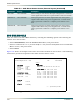
View the status of an M13 MUX module by selecting the following options and selecting the
number for a slot location:
• Select ACCESS MODULES, from the MX2820 Main Menu, and press ENTER.
• Select a number from 1 to 7 (19-inch shelf) or 1 to 9 (23-inch shelf) from the Access Module
Menus screen, and press
ENTER.
• Select STATUS.
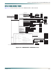
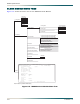
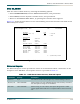
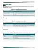
Figure 5-8 shows an example of the status for an M13 module in slot location 4. The following
subsections provide descriptions of the fields for this Status screen.
Figure 5-8. M13 MUX Module Status Screen Example
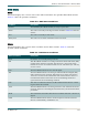
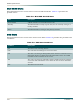
AUX #3B User Definable When acting as a fan alarm, this input will generate a cadenced
alarm signal which indicates a partial failure of the fan module.
PWR Bus A User Definable This input generates an alarm signal when one of the power
supplies fails. When both power supplies fail, a critical alarm
will be generated to indicate a complete power failure at the
SCU.
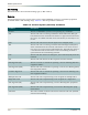
PWR Bus B User Definable This input generates an alarm signal when one of the power
supplies fails. When both power supplies fail, a critical alarm
will be generated to indicate a complete power failure at the
SCU.
Table 5-1. SCU Alarm Status Screen, External Inputs (Continued)
Input Name Severity Description
Shelf: 1 Slot: 4A ADTRAN MX2820 System 04/21/04 23:05
Unacknowledged Alarms: None TID: HTVLALEXD16
Status
DS3 State DS2 State
State = ALARM <1-7> = LOF LOF LOF LOF LOF LOF LOF
Alarm = LOS
Rx Framing = M13 T1/E1 State
Remote = Unknown <1-4> = AUTO AUTO AUTO AUTO
<5-8> = AUTO AUTO AUTO AUTO
Multiplexer State <9-12> = AUTO AUTO AUTO AUTO
Alarm = None <13-16> = AUTO AUTO AUTO AUTO
Protection = Circuit <17-20> = AUTO AUTO AUTO AUTO
Card Comm. = OK <21-24> = AUTO AUTO AUTO AUTO
<25-28> = AUTO AUTO AUTO AUTO
Slot 4A
Status = Active
Slot 4B
Status = Standby
'?' - System Help Screen