
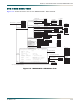
Troubleshooting guide

Section 5, User Interface Guide - UIG-510, Status
61186003L1-1D 5-23
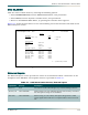
Multiplexer State
Alarm
This field displays the current alarm condition for the Multiplexer State. Table 5-5 lists the
possible alarm conditions.
Protection
This field indicates the current protection mode for the M13 MUX module. Table 5-6 provides
the possible state conditions.
Card Comm
This field indicates the current state of the communication link between the two M13 MUX
modules. Table 5-7 provides the possible conditions.
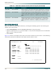
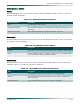
Table 5-5. Multiplexer Alarm Conditions
Alarm (Condition) Description
None No multiplexer state alarms.
Excessive Switches This condition indicates the maximum switching threshold has been
exceeded.
Switched to Protect This condition indicates a module switch has occurred.
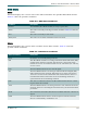
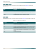
Table 5-6. M13 MUX Protection Modes
Mode Description
Circuit The unit is in Circuit Protection mode and everything is functioning.
None One M13 MUX module is installed, or the unit is in Circuit Protection
mode, and the secondary module has failed.
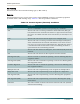
Table 5-7. M13 MUX Card Communication State
State Description
OK This condition indicates the modules are communicating.
Failure This condition indicates the modules are not able to communicate
with each other.
Non-Redundant This condition indicates only one module is installed.