
Troubleshooting guide

Section 7, User Interface Guide - DLP-503, Connect Power and Ground
61186003L1-1D 7-23
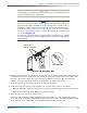
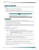
• –48 VDC B CO supply to the –48 VDC B Fan Module terminal
• –48 VDC B CO return to the –48 VDC RET B Fan Module terminal
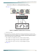
See Figure 7-3.
Figure 7-3. MX2820 Fan Module Power Connections
f. Install the fan filter.
5. For the Pusher Fan Assembly, determine the voltage requirements per system and CO
requirements, then connect the power. Use a screwdriver appropriate for the fuse panel or
circuit breaker panel and a #1 phillips-head screwdriver for the Fan Module terminals.
Connect the Pusher Fan Assembly as follows:
• ±24/–48 VDC A CO supply to the ±24/–48 VDC A IN fan terminal
• ±24/–48 VDC A CO return to the ±24/–48 VDC A RET fan terminal
• ±24/–48 VDC B CO supply to the ±24/–48 VDC B IN fan terminal
• ±24/–48 VDC B CO return to the ±24/–48 VDC B RET fan terminal
See Figure 7-4.
CD Petit Ace 25 CD Petit Ace 25 CD Petit Ace 25
ALM
B
ALM
A
-48V
DC
B
-48V
DC
A
-48V
RET
B
-48V
RET
A
ALM
B
ALM
A
-48V
DC
B
-48V
DC
A
-48V
RET
B
-48V
RET
A
USE COPPER CONDUCTORS ONLY
1181006L1
INPUT; 48VDC; 0.2A
THIS UNIT MAY BE POWERED
BY REDUNDANT POWER SOURCES
FUSE / 1 AMP
LISTED
ACCESSORY
I.T.E.
E13083
USE COPPER CONDUCTORS ONLY
-48V DC Supply
MX2820 Fan Module