
Troubleshooting guide

MX2820 System Manual
7-24 61186003L1-1D
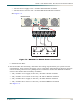
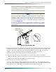
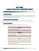
Figure 7-4. Pusher Fan Assembly Power Connections
6. Apply power and check voltage, and then remove power.
CAUTION
Installing fuses in the fuse panel or turning the circuit breaker
switches to the ON position at this stage provides power to the
shelf and fans. The fans in the Fan Module will begin to rotate, and
there will be power to pins on the backplane and inside the shelf.
Use caution to avoid electric shock.
NOTE
Before proceeding further, ensure that power has been correctly
applied to the shelf.
There are two power supply voltages available to the MX2820, based upon application
requirements:
• For a –48 VDC system, the proper voltage to the shelf is –48 VDC with an operating range
of –42 VDC to –56 VDC.
• For a ±24 VDC system, the proper voltage is + or – 24 VDC with an operating range of –
22 to –27 VDC or +22 to +27 VDC.
a. Install fuses in the slots of the fuse panel that services the shelf.
b. Use a voltmeter and place the common lead (normally black) on the RET A terminal and
the DC volts lead (normally red) on the PWR A terminal. The reading should be in the
operating range shown above. Repeat this step for the RET B terminal and the PWR B
terminal.
c. Remove the fuses from the fuse panel or turn off the circuit breakers from the circuit
breaker panel powering the shelf.
d. Install the proper-sized fuses in the slots of the fuse panel that power the Fan Module.
e. Use a voltmeter and place the common lead (normally black) on the Fan Module RET A
terminal and the DC volts lead (normally red) on the DC (IN) A terminal. The reading
A
ALM
OUT
RET
INRETIN
B