
Troubleshooting guide


MX2820 System Manual
7-32 61186003L1-1D
MATERIALS REQUIRED
Install the modules required per local application. These can include one or more of the
following:
• ADTRAN M13 MUX Module (P/N 1186002Lx)
• ADTRAN STS-1 MUX Module (P/N 1186005L1)
• ADTRAN Clock Module (P/N 1186004L1) if the STS-1 MUX Module is installed
NOTE
Other ADTRAN MX2820 modules are available. Refer to the
Job Aid for those modules for specific requirements.
PROCEDURE
1. Open the carton carefully, and remove the module from the carton.
2. After removing the module from the carton, unwrap the bubble-wrap and pull the
module from the antistatic plastic bag.
3. Immediately inspect the module for damage.
4. If the shipment has been damaged, file a claim immediately with the carrier, and
then contact ADTRAN Customer Service. For more information, refer to “Appendix
B, Warranty”.
5. Repeat steps 1 - 4 for each module.
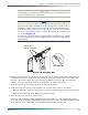
6. Install the primary module.
a. Gently but firmly push the module into the appropriate slot.
MUX: Slots are labeled 1A through 7A on the front of the 19-inch shelf and
labeled
1A through 9A on the 23-inch shelf. The primary module
should be installed in the “A” slot.
Clock: Slots are labeled CLKA and CLKB. Insert the primary clock module in
CLKA.
Simultaneous thumb pressure at the top and bottom of the module ensures a
good seat of the pins into the backplane connector.
b. Push the ejector tab up and closed against the front panel.
c. Allow the self-test LED sequence to complete. The self-test should take about 10
to 15 seconds.
d. Repeat steps a - c if additional primary modules are to be installed.
7. Provision the primary module. For details, refer to DLP-730 and DLP-741.
Return to this procedure and continue at step 11. If a protection configuration is
being deployed, proceed to step 8.