
Troubleshooting guide

Section 7, User Interface Guide - DLP-505, Install Modules in MX2820 Shelf
61186003L1-1D 7-33
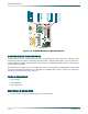
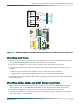
8. Install the Protect module.
a. Gently but firmly push the module into the appropriate slot
MUX: Slots are labeled 1B through 7B on the front of the 19-inch shelf and labeled
1B through 9B on the 23-inch shelf. The protect module should be installed in
the “B” slot.
Clock: Insert the protect clock module in CLKB.
b. Simultaneous thumb pressure at the top and bottom of the module ensures a good seat
of the pins into the backplane connector.
Push the ejector tab up and closed against the front panel.
c. Allow the self-test LED sequence to complete. The self-test should take about 10 to 15
seconds.
d. Repeat substeps steps a - c if additional protect modules are to be installed.
9. Insert blank front panels for vacant slots.
Insert the Clock Module blank front panel(s), P/N 1186011L1, into the first slot on the
front-left of the shelf if the Clock Module will not be used.
Insert the MX2820 MUX blank front panel(s), P/N 1186010L1, into the MUX slots that
will not be used.
10. Provision the module.
Provisioning a module in the “A” slot automatically provisions the module in the “B” slot.
For details, refer to
DLP-730 - Provision DS3/DS2 Network, DLP-741 - Provision STS-1
Network, and DLP-743 - Provision Clock Module.
11. Perform Acceptance Testing for the modules after all modules are installed and
provisioned. For details, refer to DLP-602.
FOLLOW-UP PROCEDURES
Once this procedure is complete, return to the procedure which called out this DLP and
continue with the tasks indicated.