
Troubleshooting guide


Section 7, User Interface Guide - DLP-506, Connect MX2820 Wire-Wrap Posts
61186003L1-1D 7-37
WARNING
To prevent electrical shock, do not install equipment in a wet loca-
tion or during a lightning storm.
CAUTION
Electronic modules can be damaged by static electrical discharge.
Before handling modules, wear an antistatic discharge wrist strap
to prevent damage to electronic components. Place modules in
antistatic packing material when transporting or storing. When
working on modules, always place them on an approved antistatic
mat that is electrically grounded.
PROCEDURE
Wire Wrap CHAIN Posts
1. Measure and cut three pieces of wire long enough to reach from the CHAIN wire-wrap posts
to
CHAIN wire-wrap posts of the next shelf.
2. Use the wire strippers to strip 1 inch to 2 inches from both ends of each wire.
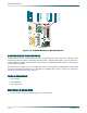
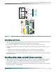
3. Use the wire-wrap tool to wrap the strands on the MX2820 backplane (see Figure 7-6) as
follows:
a. Wire wrap one strand to the CHAIN ground wire-wrap post, and route wire downward.
b. Wire wrap one strand to the CHAIN negative (-) wire-wrap post, and route wire
downward.
c. Wire wrap one strand to the CHAIN positive (+) wire-wrap post, and route wire
downward.
If additional shelves are to be wired at this time for an RS-485 configuration, make the
RS-485 Bus connection between the shelves. For details, refer to
DLP-712.
Wire Wrap MIN Alarm Relay Posts
1. Determine whether the external alarm reporting device uses a normally open or normally
closed circuit for the alarm relay.
2. Measure and cut three pieces of wire long enough to reach from the MIN wire-wrap posts to
an Alarm Relay concentrator or to the external office alarm equipment that is to be
connected to the MX2820 shelf.
3. Use the wire strippers to strip 1 inch to 2 inches from both ends of each wire.
4. Use the wire-wrap tool to wrap the strands on the MX2820 backplane (see Figure 7-6) as
follows:
a. Wire wrap one strand to the MIN center post (COM), and route wire downward.