
Troubleshooting guide

Section 7, User Interface Guide - DLP-506, Connect MX2820 Wire-Wrap Posts
61186003L1-1D 7-39
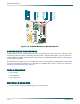
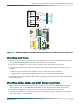
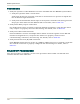
Figure 7-7. MX2820 CLKA and CLKB Terminal Connections to External Clock Source
Wire Wrap ACO Posts
1. Measure and cut three pieces of wire long enough to reach from the ACO wire-wrap posts
on the MX2820 backplane to the external office alarm equipment.
2. Use the wire strippers to strip 1 inch to 2 inches from both ends of each wire.
3. Use the wire-wrap tool to wrap the strands on the ACO input posts (see Figure 7-6) as
follows:
a. Wire wrap one strand to the lowest ACO post, and route wire downward.
b. Wire wrap one strand to the highest ACO post, and route wire downward.
4. Route the wires to the external office alarm equipment, and connect the wires according to
local instructions.
Wire Wrap AUX3, AUX2, and AUX1 Alarm Input Posts
1. Measure and cut six pieces of wire long enough to reach from the AUX3, AUX2 and AUX1
alarm input posts on the MX2820 backplane to the external office alarm equipment.
2. Use the wire strippers to strip 1 inch to 2 inches from both ends of each wire.
3. Use the wire-wrap tool to wrap the strands on the AUX3, AUX2, and AUX1 alarm input
posts (see Figure 7-6) as follows:
USE COPPER
CONDUCTORS ONLY
R8
R7
R6
R5
P4
P6
N
C
C
N
O
C
N
O
M
I
N
N
C
C
N
O
+
–
N
H
C
T
R
S
T
R
S
A
U
X
1
A
U
X
2
A
U
X
3
A
C
O
P
W
R
A
R
E
T
A
P
W
R
B
R
E
T
B
J2
J1
TB1
CLKB
R4
R10
R1
D1
R2R9
R3
D4
D3
D2
1 IN
(T1/R1)
SHLD
RNG
TIP
SHLD
RNG
TIP
+
-
S
+
-
S
C
L
K
A
C
L
K
B
External Clock Source
MX2820 Backplane