
Troubleshooting guide

Section 1, System Description - System Components
61186003L1-1D 1-9
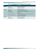
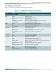
M13 MUX Module
• P/N 1186002L1 for –48 VDC (revision K and earlier)
• P/N 1186002L1 for –48 VDC or ±24 VDC (revision L and later)
• P/N 1186002L2 for –48 VDC or ±24 VDC
• P/N 1186002L5 for –48 VDC or ±24 VDC
• P/N 1186002E1 for –48 VDC or ±24 VDC
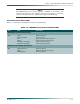
The M13 MUX module acts as a multiplexer/de-multiplexer, accepting a single DS3 input
signal and provides 28 DSX-1 or 21 E1 output signals and vice-versa. The MX2820 system
allows two M13 MUX modules for each DS3 signal which provides a 1:1 redundant system.
Each M13 MUX pair communicates with each other to share provisioning information and the
presence of signals and trouble conditions. Each M13 MUX pair communicates with the
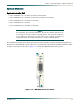
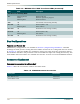
MX2820 SCU for alarm reporting and performance monitoring. Figure 1-4 shows the MX2820
M13 MUX front panel.
Figure 1-4. MX2820 M13 MUX Module Front Panel
The MX2820 M13 MUX module provides the following features:
• Built-in 1:1 equipment redundancy
• Multiplexes 28 DSX-1 (or 21 E1 channels) into a DS3 signal
• De-multiplexes a DS3 signal into 28 DSX-1 or 21 E1 channels as allowed by DS2 framing
• Supports the M13 or C-Bit parity DS3 formats
• B3ZS line code compatible
• Automatic DS3 Line Build Out (LBO) and receive equalization
1186002
MUX
ALM
ACT
TEST
STAT
TEST
STAT
DS1
DS3