
Troubleshooting guide


MX2820 System Manual
2-2 61186003L1-1D
Tables
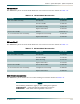
Table 2-1. MX2820 Equipment Dimensions and Weights . . . . . . . . . . . . . . . . . . . . . . . . . . . . . . . . . . . . . . . .2-3
Table 2-2. Current Draw of Each Module at –48 VDC . . . . . . . . . . . . . . . . . . . . . . . . . . . . . . . . . . . . . . . . . . . 2-4
Table 2-3. Current Draw of Each Module at ±24 VDC . . . . . . . . . . . . . . . . . . . . . . . . . . . . . . . . . . . . . . . . . . . 2-4
Table 2-4. Current Draw at –48 VDC for fully loaded M13 System . . . . . . . . . . . . . . . . . . . . . . . . . . . . . . . . . 2-5
Table 2-5. Current Draw at ±24 VDC for fully loaded M13 System . . . . . . . . . . . . . . . . . . . . . . . . . . . . . . . . . 2-5
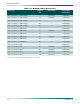
Table 2-6. Current Draw at –48 VDC for fully loaded STS-1 system . . . . . . . . . . . . . . . . . . . . . . . . . . . . . . . . 2-6
Table 2-7. Wire Gauge and Fuse Size Recommendations . . . . . . . . . . . . . . . . . . . . . . . . . . . . . . . . . . . . . . .2-6
Table 2-8. Module Heat Dissipation at –48 VDC . . . . . . . . . . . . . . . . . . . . . . . . . . . . . . . . . . . . . . . . . . . . . . . 2-7
Table 2-9. Heat Dissipation for Fully Loaded M13 System at –48 VDC. . . . . . . . . . . . . . . . . . . . . . . . . . . . . . 2-7
Table 2-10. Heat Dissipation for Fully Loaded M13 System at ±24 VDC. . . . . . . . . . . . . . . . . . . . . . . . . . . . . . 2-8
Table 2-11. Heat Dissipation for Fully Loaded STS-1 System . . . . . . . . . . . . . . . . . . . . . . . . . . . . . . . . . . . . . . 2-8
Table 2-12. Heat Dissipation for Shelf . . . . . . . . . . . . . . . . . . . . . . . . . . . . . . . . . . . . . . . . . . . . . . . . . . . . . . . 2-11
Table 2-13. Heat Dissipation for Individual Frame . . . . . . . . . . . . . . . . . . . . . . . . . . . . . . . . . . . . . . . . . . . . . . 2-11
Table 2-14. Conductor Color Code for All FutureBus-to-Stub Cable Assemblies . . . . . . . . . . . . . . . . . . . . . . 2-17
Table 2-15. Amphenol Pinout for All FutureBus-to-Amphenol Cable Assemblies . . . . . . . . . . . . . . . . . . . . . . 2-18
Table 2-16. FutureBus Connector Map . . . . . . . . . . . . . . . . . . . . . . . . . . . . . . . . . . . . . . . . . . . . . . . . . . . . . . 2-19