
Troubleshooting guide

Section 2, Engineering Guidelines - System Power Requirements
61186003L1-1D 2-5
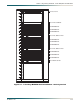
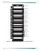
M13 and STS-1 System Configurations
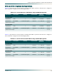
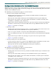
Table 2-4 provides the current draw for a fully loaded M13 system at –48 VDC for a single 19-
inch shelf and a single 23-inch shelf deployment.
Note: x indicates the list version.
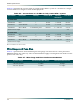
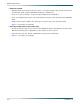
Table 2-5 provides the current draw for a fully loaded M13 system at ±24 VDC for a single 19-
inch shelf and a single 23-inch shelf deployment.
Note: x indicates the list version.
Table 2-4. Current Draw at –48 VDC for fully loaded M13 System
Part Number Description Quantity Current Draw Quantity
times Draw
Total Draw
19-inch shelf
1186003Lx SCU 1 68 mA 1 × 68 mA 68 mA
1186002Lx M13 MUX 7 redundant pairs 340 mA 7 × 340 mA 2.38 A
Total Draw in Amps 2.45 A
23-inch shelf
1186003Lx SCU 1 68 mA 1 × 68 mA 68 mA
1186002Lx M13 MUX 9 redundant pairs 340 mA 9 × 340 mA 3.06 A
Total Draw in amps 3.13 A
Table 2-5. Current Draw at ±24 VDC for fully loaded M13 System
Part Number Description Quantity Current Draw Quantity
times Draw
Total Draw
19-inch shelf
1186003Lx SCU 1 130 mA 1 × 130 mA 130 mA
1186002Lx M13 MUX 7 redundant pairs 720 mA 7 × 720 mA 5.04 A
Total Draw in Amps 5.17 A
23-inch shelf
1186003Lx SCU 1 130 mA 1 × 130 mA 130 mA
1186002Lx M13 MUX 9 redundant pairs 720 mA 9 × 720 mA 6.48 A
Total Draw in amps 6.61 A