
Specifications

Section 4, Installation - Installing the MX3 Chassis
61189008L1-1B 4-9
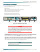
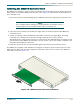
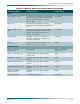
5. Connect the AUX INPUTS (1–8) used by the MX3216 system for Auxiliary Alarms 1-4.
These pins sense open and closed relay contacts and are not polarity sensitive. Table 4-2
shows the pin assignments for the alarm inputs.
NOTE
Each alarm input defaults to a severity level of major. The severity
level can be changed on the
“Environmental Alarms Menu”. Assign
any alarm input to function as an alarm cut-off (ACO).
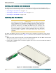
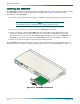
6. After steps 4 and 5 are completed, install the protective cover over the wire-wrap headers.
7. Power can now be applied to the chassis by installing appropriate fuses in the fuse and
alarm panel that services the MX3 chassis.
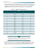
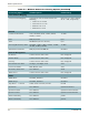
Table 4-2. AUX Inputs 1 - 8 Pin List
AUX Inputs 1 - 8 Pin List
AUX Inputs Function
1, 2 Alarm 1
3, 4 Alarm 2
5, 6 Alarm 3
7, 8 Alarm 4