NetVanta 1000 Series and NetVanta 1000R Series Hardware Installation Guide 1200500E1 NetVanta 1224 1200504E1 NetVanta 1224ST 1200510L1 NetVanta 1224STR (AC) 1200520E1 NetVanta 1224R 1200530L1 NetVanta 1224R PoE 1200560E2 NetVanta 1524ST 1200570L1 NetVanta 1224STR PoE 1200580L1 NetVanta 1224 PoE 1200584L1 NetVanta 1224ST PoE 1200590L1 NetVanta 1224STR (DC) 1700515E2 NetVanta 1335 1700515E12 NetVanta 1335 WiFi 1700525E2 NetVanta 1335 PoE 1700525E12 NetVanta 1335 WiFi PoE 4200368L1
Trademarks NetVanta 1000/1000R Series Hardware Installation Guide Trademarks Any brand names and product names included in this manual are trademarks, registered trademarks, or trade names of their respective holders. To the Holder of the Manual The contents of this manual are current as of the date of publication. ADTRAN reserves the right to change the contents without prior notice.
NetVanta 1000/1000R Series Hardware Installation Guide Conventions Conventions Notes provide additional useful information. Cautions signify information that could prevent service interruption or damage to the equipment. Warnings provide information that could prevent injury or endangerment to human life. 61200500L1-34N Copyright © 2008 ADTRAN, Inc.
Safety Instructions NetVanta 1000/1000R Series Hardware Installation Guide Safety Instructions When using your telephone equipment, please follow these basic safety precautions to reduce the risk of fire, electrical shock, or personal injury: 1. Do not use this product near water, such as a bathtub, wash bowl, kitchen sink, laundry tub, in a wet basement, or near a swimming pool. 2. Avoid using a telephone (other than a cordless type) during an electrical storm.
NetVanta 1000/1000R Series Hardware Installation Guide FCC-Required Information FCC-Required Information FCC regulations require that the following information be provided in this manual: 1. This equipment complies with Part 68 of Federal Communications Commission (FCC) rules and requirements adopted by America’s Carriers Telecommunications Association (ACTA). Each registered interface has a label that contains, among other information, a product identifier in the format US:AAAEQ##TXXXX.
FCC Radio Frequency Interference Statement NetVanta 1000/1000R Series Hardware Installation Guide FCC Radio Frequency Interference Statement This equipment has been tested and found to comply with the limits for a Class A digital device, pursuant to Part 15 of the FCC rules. These limits are designed to provide reasonable protection against harmful interference when the equipment is operated in a commercial environment.
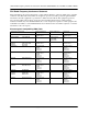
NetVanta 1000/1000R Series Hardware Installation Guide Wireless Radio Channel Ranges Wireless Radio Channel Ranges The following table lists by country the channels support by the ADTRAN WiFi products (NetVanta 1335 WiFi and NetVanta 1335 WiFi PoE only). 802.11a (5 GHz) Wireless Radios Channels Country 802.11bg (2.
Industry Canada Compliance Information NetVanta 1000/1000R Series Hardware Installation Guide Industry Canada Compliance Information Notice: The Industry Canada label applied to the product (identified by the Industry Canada logo or the “IC:” in front of the certification/registration number) signifies that the Industry Canada technical specifications were met. Notice: The REN for this terminal equipment is supplied in the documentation or on the product labeling/ markings.
Table of Contents Introduction . . . . . . . . . . . . . . . . . . . . . . . . . . . . . . . . . . . . . . . . . . . . . . . . . . . . . . . . . . . . . . . . . . . . . . . Power over Ethernet . . . . . . . . . . . . . . . . . . . . . . . . . . . . . . . . . . . . . . . . . . . . . . . . . . . . . . . . . . . . . Wireless Access . . . . . . . . . . . . . . . . . . . . . . . . . . . . . . . . . . . . . . . . . . . . . . . . . . . . . . . . . . . . . . . . . SFP Module Slots . . . . . . . . . . . . . . . . .
Table of Contents 10 NetVanta 1000/1000R Series Hardware Installation Guide Copyright © 2008 ADTRAN, Inc.
List of Figures Figure 1. Figure 2. Figure 3. Figure 4. Figure 5. Figure 6. Figure 7. Figure 8. Figure 9. Figure 10. Figure 11. Figure 12. Figure 13. Figure 14. Figure 15. Figure 16. Figure 17. Figure 18. Figure 19. Figure 20. Figure 21. Figure 22. Figure 23. Figure 24. Figure 25. Figure 26. Figure 27. Figure 28. Figure 29. Figure 30. Figure 31. Figure 32. Figure 33. Figure 34. Figure 35. Figure 36. Figure 37. Figure 38. Figure 39. Figure 40. Figure 41. Figure 42. Figure 43.
List of Figures 12 NetVanta 1000/1000R Series Hardware Installation Guide Copyright © 2008 ADTRAN, Inc.
List of Tables Table 1. Front Panel LED Descriptions . . . . . . . . . . . . . . . . . . . . . . . . . . . . . . . . . . . . . . . . . . . . . . . . 33 Table 2. 3G CDMA NIM LED Descriptions . . . . . . . . . . . . . . . . . . . . . . . . . . . . . . . . . . . . . . . . . . . . . 49 Table 3. Primary Antenna Specifications . . . . . . . . . . . . . . . . . . . . . . . . . . . . . . . . . . . . . . . . . . . . . . . 63 Table 4. Diversity Antenna Specifications . . . . . . . . . . . . . . . . . . . . . . . . .
List of Tables 14 NetVanta 1000/1000R Series Hardware Installation Guide Copyright © 2008 ADTRAN, Inc.
1. INTRODUCTION The NetVanta 1000 Series includes the NetVanta 1224, NetVanta 1224 PoE, NetVanta 1224ST, NetVanta 1224ST PoE, NetVanta 1335, NetVanta 1335 PoE, NetVanta 1335 WiFi, NetVanta 1335 WiFi PoE, and the NetVanta 1524ST. The NetVanta 1000R Series includes the NetVanta 1224R, NetVanta 1224R PoE, NetVanta 1224STR (AC), NetVanta 1224STR (DC), and NetVanta 1224STR PoE.
Physical Descriptions 2. NetVanta 1000/1000R Series Hardware Installation Guide PHYSICAL DESCRIPTIONS NetVanta 1224 The NetVanta 1224 is a managed switch housed in a 1U-high rack-mountable metal enclosure that includes a universal AC power supply. The front panel contains 24 10/100BaseT Ethernet interfaces (RJ-45). The NetVanta 1224 PoE version provides the ability to detect attached PDs, and deliver 48 VDC to the PDs via existing CAT 5 cabling.
NetVanta 1000/1000R Series Hardware Installation Guide Physical Descriptions NetVanta 1224 Front Panel Features 10/100BaseT Ethernet Interfaces The NetVanta 1224s contain 24 10/100BaseT Ethernet interfaces (RJ-45). These interfaces are consecutively numbered 1 through 24, from left to right, with the numbers screened directly above each port. Status LEDs for each of these interfaces are located directly over these numbers.
Physical Descriptions NetVanta 1000/1000R Series Hardware Installation Guide NetVanta 1224ST The NetVanta 1224ST and NetVanta 1224ST PoE are managed switches housed in a 1U-high rack-mountable metal enclosure that includes a universal AC power supply. The front panel contains 24 10/100BaseT Ethernet interfaces (RJ-45). The NetVanta 1224ST front panel contains two Gigabit Ethernet interfaces that provide two fixed RJ-45 connectors and two standard SFP slots for fiber connectivity.
NetVanta 1000/1000R Series Hardware Installation Guide Physical Descriptions NetVanta 1224ST Front Panel Features 10/100BaseT Ethernet Interfaces The NetVanta 1224STs contain 24 10/100BaseT Ethernet interfaces (RJ-45). These interfaces are consecutively numbered 1 through 24, from left to right, with the numbers screened directly above each port. Status LEDs for each of these interfaces are located directly over these numbers.
Physical Descriptions NetVanta 1000/1000R Series Hardware Installation Guide NetVanta 1224ST Rear Panel Interfaces CONSOLE Interface The CONSOLE interface is an EIA-232 serial port (DCE) that provides for local management and configuration (via a DB-9 female connector). Connection directly to an external modem requires a cross-over cable. Power Connection The rear panel has a power input to the AC universal power supply. Please refer to Supplying Power to the Unit on page 56 for connection details.
NetVanta 1000/1000R Series Hardware Installation Guide Physical Descriptions NetVanta 1224R Shipping Contents Each NetVanta 1224R and NetVanta 1224R PoE unit is shipped in its own cardboard shipping carton. Open each carton carefully, and avoid deep penetration into the carton with sharp objects. After unpacking the unit, inspect it for possible shipping damage.
Physical Descriptions NetVanta 1000/1000R Series Hardware Installation Guide Status LEDs The status LEDs are located to the lower left of RJ-45 port 1. The WAN LED reflects the status of an installed NIM. The DBU LED reflects the status of an installed dial backup interface module (DIM). The STAT LED indicates the unit’s status. Figure 7. NetVanta 1224R Front Panel Layout Figure 8.
NetVanta 1000/1000R Series Hardware Installation Guide Physical Descriptions NetVanta 1224STR The NetVanta 1224STR (AC and DC versions) and NetVanta 1224STR PoE are managed switches housed in a 1U-high rack-mountable metal enclosure that includes either a universal AC or a DC power supply. The NetVanta 1224STR PoE version provides the ability to detect attached PDs, and deliver 48 VDC to the PDs via existing CAT 5 cabling. Both front panels contain 24 10/100BaseT Ethernet interfaces (RJ-45).
Physical Descriptions • • • • NetVanta 1000/1000R Series Hardware Installation Guide AOS Documentation CD A detachable power cable with a grounded, three-prong plug Quick Start Guide Warranty card International shipments of the NetVanta 1224STR include the following items: • • • • • NetVanta 1224STR base unit AOS Documentation CD All necessary power cords Quick Start Guide Warranty card NetVanta 1224STR Front Panel Design The NetVanta 1224STR and the NetVanta 1224STR PoE front panels are shown below.
NetVanta 1000/1000R Series Hardware Installation Guide Physical Descriptions Status LEDs The status LEDs are located to the lower left of RJ-45 port 1. The WAN LED reflects the status of an installed NIM. The DBU LED reflects the status of an installed DIM. The STAT LED indicates the unit’s status. Figure 10. NetVanta 1224STR (AC) Front Panel Layout Figure 11. NetVanta 1224STR (DC) Front Panel Layout Figure 12.
Physical Descriptions NetVanta 1000/1000R Series Hardware Installation Guide CONSOLE Interface The CONSOLE interface is an EIA-232 serial port (DCE) that provides for local management and configuration (via a DB-9 female connector). Connection directly to an external modem requires a cross-over cable. Power Connection The rear panel of the NetVanta 1224STR (AC) and NetVanta 1224STR PoE have a power input for connection to an AC universal power supply.
NetVanta 1000/1000R Series Hardware Installation Guide • • • Physical Descriptions Product Specifications on page 34 Mounting Options on page 54 Supplying Power to the Unit on page 56 For information on router configuration for a specific application, refer to the quick configuration documents provided on the AOS Documentation CD shipped with your base unit. For details on the CLI, refer to the AOS Command Reference Guide (also included on your CD).
Physical Descriptions NetVanta 1000/1000R Series Hardware Installation Guide Gigabit Ethernet Interfaces/SFP Slots The NetVanta 1335 and NetVanta 1335 PoE contain two Gigabit Ethernet interfaces that provide two fixed RJ-45 connectors and two standard SFP slots for fiber connectivity. These interfaces are labeled G1 and G2, and the status LEDs are located above the SFP slots.
NetVanta 1000/1000R Series Hardware Installation Guide Physical Descriptions Status LEDs The status LEDs are located to the lower left of RJ-45 port 1. The WLAN LED (NetVanta 1335 WiFi Series only) reflects the status of the wireless network. The WAN LED reflects the status of an installed NIM. The DBU LED reflects the status of an installed DIM. The STAT LED indicates the unit’s status. Figure 15. NetVanta 1335 Front Panel Layout NetVanta 1335 Figure 16.
Physical Descriptions NetVanta 1000/1000R Series Hardware Installation Guide NetVanta 1335 Rear Panel Interfaces NIM Option Slot The NIM option slot accepts a variety of NIM option modules (refer to Option Modules on page 35). CompactFlash The CompactFlash slot supplies nonvolatile configuration and compressed code storage. The NetVanta 1335 supports only ADTRAN-provided CompactFlash (16 MB to 1 GB) (refer to the part number on the front cover of this manual).
NetVanta 1000/1000R Series Hardware Installation Guide Physical Descriptions NetVanta 1524ST Shipping Contents Each NetVanta 1524ST unit is shipped in its own cardboard shipping carton. Open each carton carefully, and avoid deep penetration into the carton with sharp objects. After unpacking the unit, inspect it for possible shipping damage.
Physical Descriptions NetVanta 1000/1000R Series Hardware Installation Guide NetVanta 1524ST Rear Panel Design The NetVanta 1524ST rear panel is shown below. Refer to Appendix A on page 67 for pinouts. Figure 22. NetVanta 1524ST Rear Panel Layout NetVanta 1524ST Rear Panel Interfaces 10/100BaseT Ethernet Interface The Ethernet port (ETH 0/0) is an RJ-45 connector. The Ethernet port provides the following: • 10BaseT or 100BaseT with a single connector • Auto-negotiation • CSMA/CD • IEEE 802.
NetVanta 1000/1000R Series Hardware Installation Guide Physical Descriptions Table 1. Front Panel LED Descriptions LED STAT Color Indication Off Unit is not receiving power. Green (solid) Power is on and self-test passed. Green (flashing) On power-up the STAT LED flashes rapidly for five seconds, during which time the user may escape to boot mode from the CONSOLE port. Red (solid) Power is on, but the self-test failed or the boot code could not be booted. Off Unit is not a member of a stack.
Product Specifications NetVanta 1000/1000R Series Hardware Installation Guide 1224 1224ST 1224STR (AC) 1224STR (DC) 1224STR PoE 1224R 1335, 1335 PoE 1335 WiFi Series 1524ST 3.
NetVanta 1000/1000R Series Hardware Installation Guide 4. Option Modules OPTION MODULES The NetVanta 1224STR, 1224R, and 1335 support several option modules designed to meet a variety of networking requirements. The option modules include plug-in NIMs and plug-on DIMs. NIMs are cards that plug directly into the option module slot located on the rear of the base unit.
Option Modules NetVanta 1000/1000R Series Hardware Installation Guide Network Interface Modules NetVanta 56K/64K NIM (P/N 1200861L1) The 56K/64K NIM (shown in Figure 23) provides a DDS WAN interface for the NetVanta. This module provides a single 56K or 64K DDS network interface. See Table A-5 on page 69 for the WAN-DDS connector pinouts, and page 73 for the DBU connector pinouts. An optional DIM is required for dial backup applications. Figure 23.
NetVanta 1000/1000R Series Hardware Installation Guide Option Modules NetVanta T1/FT1 NIM (P/N 1202862L1) The T1/FT1 NIM (shown in Figure 24) provides a T1 WAN interface for the NetVanta. This module provides a full T1 or fractional T1 network interface. See Table A-6 on page 69 for the WAN-T1 connector pinouts, and page 73 for the DBU connector pinouts. An optional DIM is required for dial backup applications. WAN-T1 DBU Figure 24.
Option Modules NetVanta 1000/1000R Series Hardware Installation Guide NetVanta T1/FT1 NEBS NIM (P/N 1200862L2#NEBS) The T1/FT1 NEBS NIM (see Figure 25) T1 WAN interface for the NetVanta 1224STR DC. The T1 NEBS NIM is NEBS Level 3 compliant, and provides a full T1 or fractional T1 network interface. See Table A-6 on page 69 for the WAN-T1 connector pinouts. Although the T1/FT1 NEBS NIM is compliant with NEBS Level 3, the NetVanta 1224STR DC unit supports only NEBS Level 1. WAN-T1 Figure 25.
NetVanta 1000/1000R Series Hardware Installation Guide Option Modules NetVanta T1/FT1 + DSX-1 NIM (P/N 1202863L1) The T1/FT1 + DSX-1 NIM (see Figure 26) provides a T1 WAN interface for the NetVanta, a full or fractional T1 network interface, and a DSX-1 interface. See the pinouts in Table A-6 on page 69 for the WAN-T1 connector, Table A-8 on page 70 for the DSX-1 connector, and page 73 for the DBU connector pinouts. An optional DIM is required for dial backup applications. WAN-T1 DSX-1 DBU Figure 26.
Option Modules NetVanta 1000/1000R Series Hardware Installation Guide NetVanta Dual T1 NIM (P/N 1200872L1) The NetVanta Dual T1 NIM (see Figure 27) provides two T1 WAN interfaces for the NetVanta. See Table A-6 on page 69 for the pinouts. See page 73 for the DBU connector pinouts. An optional DIM is required for dial backup applications. WAN T1/1 WAN T1/2 DBU Figure 27.
NetVanta 1000/1000R Series Hardware Installation Guide Option Modules NetVanta E1/FE1 NIM (P/N 1200868E1/L1) The NetVanta E1/FE1 module (see Figure 28) provides a WAN-E1 interface for the NetVanta meeting the requirements of ITU-T G.703/G.704. The module provides a single 2.048 Mbps network interface. See Table A-7 on page 69 for the pinouts. See page 73 for the DBU connector pinouts. An optional DIM is required for dial backup applications. WAN-E1 DBU Figure 28.
Option Modules NetVanta 1000/1000R Series Hardware Installation Guide NetVanta E1/FE1 + G.703 Drop NIM (P/N 1200878E1/L1) The NetVanta E1/FE1 + G.703 Drop NIM (see Figure 29) provides a single WAN-E1 interface (2.043 Mbps) with user-selectable TS0 assignment, and a G.703 drop port that may be used to drop and insert traffic to an E1 PBX. See Table A-7 on page 69 for the WAN-E1 pinouts. See Table A-9 on page 70 for the G.703 pinouts. See page 73 for the DBU connector pinouts.
NetVanta 1000/1000R Series Hardware Installation Guide Option Modules NetVanta Serial NIM (P/N 1200866E1) The NetVanta Serial NIM (shown in Figure 30) can be configured by the user as a V.35, X.21 (V.11), or EIA 530 interface. This module supports rates up to a maximum of 10 Mbps. An additional V.35 (ADTRAN P/N 1200873L1), X.21 (ADTRAN P/N 1200874L1), or EIA 530 (ADTRAN P/N 1200883L1) cable is required (refer to Caution, below).
Option Modules NetVanta 1000/1000R Series Hardware Installation Guide NetVanta SHDSL NIM, Annex A (P/N 1200936E1) The NetVanta SHDSL NIM, Annex A (shown in Figure 31) provides a WAN SHDSL interface for the NetVanta. See Table A-10 on page 70 for the SHDSL connector pinouts. WAN-SHDSL ANNEX A Figure 31.
NetVanta 1000/1000R Series Hardware Installation Guide Option Modules NetVanta SHDSL NIM, Annex B (P/N 1200937E1) The NetVanta SHDSL NIM, Annex B (shown in Figure 32) provides a WAN SHDSL interface for the NetVanta. See Table A-10 on page 70 for the SHDSL connector pinouts. WAN-SHDSL ANNEX B Figure 32.
Option Modules NetVanta 1000/1000R Series Hardware Installation Guide NetVanta ADSL NIM, Annex A (P/N 1202869E1) The NetVanta ADSL NIM, Annex A (see Figure 33) adds ADSL capability to the NetVanta. The module provides a single ADSL, ADSL2, or ADSL2+ network interface to support rates up to 25 Mbps. See Table A-11 on page 71 for the pinouts. The ADSL NIM supports an optional DIM for dial backup applications. See page 73 for the DBU connector pinouts. WAN-ADSL DBU Figure 33.
NetVanta 1000/1000R Series Hardware Installation Guide Option Modules NetVanta ADSL NIM, Annex B (P/N 1202889E1) The NetVanta ADSL NIM, Annex B (see Figure 34) adds ADSL capability to the NetVanta. See Table A-11 on page 71 for the pinouts. The ADSL NIM supports an optional DIM for dial backup applications.See page 73 for the DBU connector pinouts. WAN-ADSL DBU Figure 34.
Option Modules NetVanta 1000/1000R Series Hardware Installation Guide NetVanta 3G CDMA NIM (P/N 1700801G1) The NetVanta 3G CDMA NIM (shown in Figure 35) provides a cellular interface for the NetVanta 1335 and NetVanta 1335 PoE. Refer to Installing the 3G CDMA NIM Antennas on page 62 for information about the specifications and installation of the 3G CDMA NIM antennas.
NetVanta 1000/1000R Series Hardware Installation Guide Option Modules Table 2. 3G CDMA NIM LED Descriptions LED Label WWAN RSSI (Received Signal Strength Indication) 1xRTT EVDO 61200500L1-34N LED Color Indication Off 3G modem is not powered. Green (solid) 3G modem is powered, associated, and authenticated, but not transmitting or receiving. Green (slow flash) 3G modem is powered and searching, but not associated or authenticated.
Option Modules NetVanta 1000/1000R Series Hardware Installation Guide Dial Backup Interface Modules NetVanta Analog Modem DIM (P/N 1200864L1) The Analog Modem DIM provides a modem with data rates up to 33.6 kbps for the NetVanta. This DIM is a plug-on card that connects to the NIM. For installation instructions, refer to Installing Dial Backup and Network Interface Modules on page 57. Features and Specifications Features • • Supported Standards: ITU V.
NetVanta 1000/1000R Series Hardware Installation Guide Option Modules NetVanta ISDN BRI DIM (P/N 1200865L1) The NetVanta ISDN BRI DIM provides dial backup access to the public switched telephone network (PSTN) via Basic Rate ISDN for the NetVanta. This DIM is a plug-on module that connects to the NIM. For installation instructions, refer to Installing Dial Backup and Network Interface Modules on page 57.
Option Modules NetVanta 1000/1000R Series Hardware Installation Guide NetVanta ISDN S/T DIM (P/N 1200875L1) The NetVanta ISDN S/T DIM provides dial backup access to the PSTN via Basic Rate ISDN for the NetVanta. This DIM is a plug-on module that connects to the NIM. For installation instructions, refer to Installing Dial Backup and Network Interface Modules on page 57.
NetVanta 1000/1000R Series Hardware Installation Guide 5. Unit Installation UNIT INSTALLATION The instructions and guidelines provided in this section cover hardware installation topics, such as mounting options, supplying power to the unit, and installing option cards.
Unit Installation NetVanta 1000/1000R Series Hardware Installation Guide Mounting Options The unit may be installed in rackmount, wallmount, or tabletop configurations. The following sections provide step-by-step instructions for rack mounting and wall mounting. If you have purchased the VPN Accelerator Card for your NetVanta 1224STR, install it first (refer to Installing the NetVanta VPN Accelerator Card (included in P/N 4200368L1) on page 60).
NetVanta 1000/1000R Series Hardware Installation Guide Unit Installation Wall Mounting the NetVanta By following these instructions exactly, the NetVanta can be safely mounted to the wall. Instructions for Wall Mounting the NetVanta Step Action 1 Remove the mounting ears. Rotate them 90 degrees so that the portion of the bracket with the mounting holes is flush with the bottom of the chassis. Reattach the mounting ears to the chassis (see Figure 36). 2 Decide on a location for the NetVanta.
Unit Installation NetVanta 1000/1000R Series Hardware Installation Guide Supplying Power to the Unit NetVanta 1000 and 1000R Series AC-Powered Units The AC-powered NetVanta 1000 and 1000R Series units come equipped with an auto-sensing 100 to 250 VAC, 50/60 Hz power supply for connecting to a properly grounded power receptacle. (A detachable power cable with a grounded, three-prong plug comes with the shipment.) To power these units, connect the power cable to an appropriate AC power source.
NetVanta 1000/1000R Series Hardware Installation Guide Unit Installation To comply with GR-1089-CORE, Issue 3, this equipment MUST only be installed in a DC-C (common) bonding and grounding environment. It may not be utilized in a DC-I (isolated) bonding and grounding environment. Figure 37. Grounding the NetVanta 1224STR (DC) Installing Dial Backup and Network Interface Modules The DIM plugs on to the NIM. The NIM is then installed into the rear panel option module slot.
Unit Installation NetVanta 1000/1000R Series Hardware Installation Guide Instructions for Installing the DIMs Step Action 1 Remove power from the unit. 2 If the NIM is already in the NetVanta chassis, remove all cables, release the pins at both edges of the NIM front panel and slide the module out of the chassis. 3 Carefully align the P1 connector on the NIM with the J1 connector on the DIM.
NetVanta 1000/1000R Series Hardware Installation Guide Unit Installation Instructions for Installing the NIMs Step Action 1 Remove power from the unit. 2 Slide the option module into the option slot until the module is firmly seated against the chassis. 3 Secure the pins at both edges of the module. 4 Connect the cables to the associated device(s). 5 Restore power to the unit. WAN-T1 DSX-1 DBU Figure 39. NIM and DIM Installation 61200500L1-34N Copyright © 2008 ADTRAN, Inc.
Unit Installation NetVanta 1000/1000R Series Hardware Installation Guide Installing the NetVanta VPN Accelerator Card (included in P/N 4200368L1) The optional VPN Accelerator card plugs into a 32-bit PCI slot and is designed to be used in the NetVanta 1224STR to provide encryption/decryption and security acceleration services. The card provides the following security services to the host processor: DES, triple-DES (3DES), AES, SHA-1, MD5, and random number generation.
NetVanta 1000/1000R Series Hardware Installation Guide Unit Installation Installing a CompactFlash Card (NetVanta 1335 Series only) The CompactFlash slot on the NetVanta 1335 Series supports CompactFlash cards (16 MB to 1 GB). ADTRAN supports only ADTRAN-provided CompactFlash (16 MB to 1 GB) (refer to the list of part numbers on the front cover). Follow these instructions when installing a card. The CompactFlash card is hot-swappable and can be inserted or removed while power is applied to the unit.
Unit Installation NetVanta 1000/1000R Series Hardware Installation Guide Installing Wireless Access Antennas (NetVanta 1335 WiFi and NetVanta 1335 WiFi PoE only) The NetVanta 1335 WiFi Series units are shipped with two dual-band RP-SMA detachable antennas. These must be installed before operating the unit. Instructions for Installing Antennas Step Action 1 Place either of the two antennas directly onto the antenna port labeled ANT 1 on the rear panel. See Figure 20 on page 29 for port locations.
NetVanta 1000/1000R Series Hardware Installation Guide Unit Installation Table 3. Primary Antenna Specifications Description Minimum Maximum Unit Peak Antenna Gain 1.0 dBi Average Gain -3.0 dBi Efficiency -4.0 (40) dB (%) Polarization (Ratio Gv: Gh) 0.0 dB Input VSWR 2.5:1 Average Power Handling 2.0 watts Table 4. Diversity Antenna Specifications Description Minimum Maximum Unit Average Gain -9.0 dBi Efficiency -10.0 (10) dB (%) Polarization (Ratio Gv: Gh) 0.
Unit Installation NetVanta 1000/1000R Series Hardware Installation Guide Antenna Extensions Coaxial cable can be connected to the standard SMA antenna connectors to extend the placement distance of the antennas from the 3G NIM base unit. Using cables introduces signal loss in the antenna system, but can be minimized by minimizing the length of cable used and using low-loss or ultralow-loss antenna cables. Cables that do not match the antenna specifications are strictly prohibited for use with this device.
NetVanta 1000/1000R Series Hardware Installation Guide Unit Installation Antenna Installation Instructions Instructions for Installing the 3G NIM Antennas Step Action 1 Remove power from the base unit. 2 Place either of the two antennas directly onto the antenna port labeled ANT1 on the rear panel. 3 Using the thumb screws only, carefully thread the antenna onto the connector until it is secure. 4 Repeat Step 2 with the second antenna, attaching it to the ANT2 (diversity) port.
Unit Installation 66 NetVanta 1000/1000R Series Hardware Installation Guide Copyright © 2008 ADTRAN, Inc.
APPENDIX A. CONNECTOR PIN DEFINITIONS The following tables provide the pin assignments for the base unit, NIMs, and DIMs. Base Unit Pinouts Table A-1. CONSOLE Port Pinouts Pin Name Description 1 DCD 2 RD Receive Data (output) 3 TD Transmit Data (input) 4 DTR 5 SG 6 DSR 7 — 8 CTS 9 — Data Carrier Detect (output) Data Terminal Ready (input) Signal Ground Data Set Ready Tied to pin 1 (output) Unused Clear to Send Tied to pin 1 (output) Unused Table A-2.
Appendix A. Connector Pin Definitions NetVanta 1000/1000R Series Hardware Installation Guide Table A-3. 10/100Base-T Ethernet Port Pinouts Pin Name Description 1 TX1 Transmit Positive 2 TX2 Transmit Negative 3 RX1 Receive Positive 4, 5 — 6 RX2 7, 8 — Unused Receive Negative Unused Table A-4.
NetVanta 1000/1000R Series Hardware Installation Guide Appendix A. Connector Pin Definitions Network Interface Module Pinouts Table A-5. WAN-DDS Connector Pinouts Pin Name Description 1 R1 Transmit data to the network–Ring 1 2 T1 Transmit data to the network–Tip 1 3-6 — Unused 7 T Receive data from the network–Tip 8 R Receive data from the network–Ring Table A-6.
Appendix A. Connector Pin Definitions NetVanta 1000/1000R Series Hardware Installation Guide Table A-8. DSX-1 Connector Pinouts Pin Name Description 1 R Transmit data toward the DTE–Ring 2 T Transmit data toward the DTE–Tip 3 — Unused 4 R1 Receive data from the DTE–Ring 1 5 T1 Receive data from the DTE–Tip 1 6-8 — Unused Table A-9. G.
NetVanta 1000/1000R Series Hardware Installation Guide Appendix A. Connector Pin Definitions Table A-11. WAN-ADSL Connector Pinouts Pin Name Description 1, 2 — Unused 3 R ADSL Ring 4 T ADSL Tip 5, 6 — Unused Table A-12. Serial to Cable Connector Pinouts Serial Pin V.35 Pin X.21 Pin EIA 530 Pin Name 1 P 2 2 TD_A 2 U N/A 24 ETC_A 3 Y N/A 15 TCLK_A 4 V 6 17 RCLK_A 5 R 4 3 RD_A 6 F N/A 8 DCD_A 7 H N/A 20 DTR_A 8 C 3 4 RTS_A 9 N/A 10 19 RTS_B (V.
Appendix A. Connector Pin Definitions NetVanta 1000/1000R Series Hardware Installation Guide Table A-13. Analog Station (FXS) and Analog Trunk (FXO) Port Pinouts 72 Pin Name Description 1, 2 — 3 Ring 4 Tip Tip lead of the 2-wire interface 5, 6 — Unused Unused Ring lead of the 2-wire interface Copyright © 2008 ADTRAN, Inc.
NetVanta 1000/1000R Series Hardware Installation Guide Appendix A. Connector Pin Definitions Dial Backup Interface Module Pinouts (DBU Connector) An optional DIM is required for dial backup applications. Table A-14. Analog Modem and ISDN BRI DBU Connector Pinouts Pin Name Description 1-3 — Unused 4 R Network–Ring 5 T Network–Tip 6-8 — Unused Table A-15.
Appendix A. Connector Pin Definitions 74 NetVanta 1000/1000R Series Hardware Installation Guide Copyright © 2008 ADTRAN, Inc.
Index Numerics M 1000BaseLX single-mode SFP module 15 1000BaseSX multi-mode SFP module 15 56K/64K NIM 36 mounting options 54 A ADSL, Annex A module 46 ADSL, Annex B module 47 ADTRAN operating system 15 antenna connectors 30 antennas 15, 26 C command line interface 53 CompactFlash 26, 30 installing a CompactFlash card 61 console port description 15 D DBU LED 33 Dial Backup Interface Modules Analog Modem 50 ISDN BRI 51 ISDN S/T 52 DIMs, installing 57 dual T1 NIM 40 E E1/FE1 + G.
Index P pinouts 10/100Base-T ports 68 1000Base-T ports 68 ADSL connector 71 console port 67 DBU connector 73 DDS connector 69 DSX-1 connector 70 E1 connector 69 FXS and FXO 72 G.