NetVanta 3200/3300/3400 Series Routers Hardware Installation Guide 1203860G1 NetVanta 3200 1203870G1 NetVanta 3205 (AC Version) 1203980G1 NetVanta 3205 (DC Version) 1202880E1 NetVanta 3305 1202820G1 NetVanta 3430 1200821E1 NetVanta 3448 1200823G1 NetVanta 3450 1200824G1 NetVanta 3458 1200861L1 NetVanta 56K/64K Network Interface Module 1202862L1 NetVanta T1/FT1 Network Interface Module 1200862L2#NEBS NetVanta T1/FT1 NEBS Network Interface Module 1202863L1 NetVanta T1/FT1 + DSX-1 Networ
Trademarks NetVanta 3200/3300/3400 Series Trademarks Any brand names and product names included in this manual are trademarks, registered trademarks, or trade names of their respective holders. To the Holder of the Manual The contents of this manual are current as of the date of publication. ADTRAN reserves the right to change the contents without prior notice.
NetVanta 3200/3300/3400 Series Conventions Conventions Notes provide additional useful information. Cautions signify information that could prevent service interruption or damage to the equipment. Warnings provide information that could prevent injury or endangerment to human life. 61200860L1-34AB Copyright © 2012 ADTRAN, Inc.
Safety Instructions NetVanta 3200/3300/3400 Series Safety Instructions When using your telephone equipment, please follow these basic safety precautions to reduce the risk of fire, electrical shock, or personal injury: 1. Do not use this product near water, such as a bathtub, wash bowl, kitchen sink, laundry tub, in a wet basement, or near a swimming pool. 2. Avoid using a telephone (other than a cordless type) during an electrical storm. There is a remote risk of shock from lightning. 3.
NetVanta 3200/3300/3400 Series FCC-Required Information FCC-Required Information FCC regulations require that the following information be provided in this manual: 1. This equipment complies with Part 68 of Federal Communications Commission (FCC) rules and requirements adopted by America’s Carriers Telecommunications Association (ACTA). Each registered interface has a label that contains, among other information, a product identifier in the format US:AAAEQ##TXXXX.
FCC Radio Frequency Interference Statement NetVanta 3200/3300/3400 Series FCC Radio Frequency Interference Statement This equipment has been tested and found to comply with the limits for a Class A digital device, pursuant to Part 15 of the FCC rules. These limits are designed to provide reasonable protection against harmful interference when the equipment is operated in a commercial environment.
NetVanta 3200/3300/3400 Series Industry Canada Compliance Information Industry Canada Compliance Information Notice: The Industry Canada label applied to the product (identified by the Industry Canada logo or the “IC:” in front of the certification/registration number) signifies that the Industry Canada technical specifications were met. Notice: The REN for this terminal equipment is supplied in the documentation or on the product labeling/markings.
Service and Warranty 8 NetVanta 3200/3300/3400 Series Copyright © 2012 ADTRAN, Inc.
Table of Contents Introduction . . . . . . . . . . . . . . . . . . . . . . . . . . . . . . . . . . . . . . . . . . . . . . . . . . . . . . . . . . . . . . . . . . . . . . . 15 Physical Descriptions . . . . . . . . . . . . . . . . . . . . . . . . . . . . . . . . . . . . . . . . . . . . . . . . . . . . . . . . . . . . . . . NetVanta 3200 . . . . . . . . . . . . . . . . . . . . . . . . . . . . . . . . . . . . . . . . . . . . . . . . . . . . . . . . . . . . . . . . . .
Table of Contents NetVanta 3200/3300/3400 Series NetVanta SHDSL NIM, Annex B (P/N 1200937E1) . . . . . . . . . . . . . . . . . . . . . . . . . . . . . . . . . . . NetVanta ADSL NIM, Annex A (P/N 1202869E1) . . . . . . . . . . . . . . . . . . . . . . . . . . . . . . . . . . . . NetVanta ADSL NIM, Annex B (P/N 1202889E1) . . . . . . . . . . . . . . . . . . . . . . . . . . . . . . . . . . . . NetVanta USB WWAN NIM (P/N 1702803F1) . . . . . . . . . . . . . . . . . . . . . . . . . . . . . . . . . . . . . .
List of Figures Figure 1. Figure 2. Figure 3. Figure 4. Figure 5. Figure 6. Figure 7. Figure 8. Figure 9. Figure 10. Figure 11. Figure 12. Figure 13. Figure 14. Figure 15. Figure 16. Figure 17. Figure 18. Figure 19. Figure 20. Figure 21. Figure 22. Figure 23. Figure 24. Figure 25. Figure 26. Figure 27. Figure 28. Figure 29. Figure 30. Figure 31. Figure 32. Figure 33. Figure 34. Figure 35. Figure 36. Figure 37. Figure 38. Figure 39. Figure 40. Figure 41. Figure 42. Figure 43.
List of Figures 12 NetVanta 3200/3300/3400 Series Copyright © 2012 ADTRAN, Inc.
List of Tables Table 1. Table A-1. Table A-2. Table A-3. Table A-4. Table A-5. Table A-6. Table A-7. Table A-8. Table A-9. Table A-10. Table A-11. Table A-12. Table A-13. Table A-14. Table A-15. Table A-16. NetVanta 3000 Series Front Panel LEDs . . . . . . . . . . . . . . . . . . . . . . . . . . . . . . . . . . . . . 10/100Base-T Ethernet Port Pinouts . . . . . . . . . . . . . . . . . . . . . . . . . . . . . . . . . . . . . . . . . CONSOLE Port (DCE) Pinouts for NetVanta 3200, 3205, 3430, and 3448 . . . .
List of Tables 14 NetVanta 3200/3300/3400 Series Copyright © 2012 ADTRAN, Inc.
1. INTRODUCTION The NetVanta 3200/3300/3400 Series includes the NetVanta 3200, NetVanta 3205 (AC or DC powered), NetVanta 3305, NetVanta 3430, NetVanta 3448, NetVanta 3450, and NetVanta 3458. In this document, the term NetVanta 3200/3300/3400 Series means all of the units collectively. If a statement only applies to one particular router, the text refers to the router individually.
Physical Descriptions 2. NetVanta 3200/3300/3400 Series PHYSICAL DESCRIPTIONS NetVanta 3200 The NetVanta 3200 is a modular access router designed for cost-effective branch office connectivity over MPLS, Frame Relay, multilink Frame Relay, Point-to-Point Protocol (PPP), Multilink PPP (MLPPP), or Ethernet networks. For information on switch configuration for a specific application, refer to the configuration guides provided on the ADTRAN Support Community.
NetVanta 3200/3300/3400 Series Physical Descriptions Network Interface Modules and Dial Backup Interface Modules Supported The NetVanta 3200 supports a variety of interchangeable network interface modules (NIMs) and dial backup interface modules (DIMs). The NIMs available for the NetVanta 3200 provide a variety of WAN connectivity options including the following: • • • • • • • • • 56K/64K (DDS) T1/FT1 T1/FT1 + DSX-1 Dual T1 E1/FE1 E1/FE1 + G.703 Serial (V.35/X.
Physical Descriptions NetVanta 3200/3300/3400 Series NetVanta 3200 Front Panel Design The NetVanta 3200 front panel is shown below. Front panel LED descriptions are given in Table 1 on page 40. Figure 1. NetVanta 3200 Front Panel Layout NetVanta 3200 Rear Panel Design The NetVanta 3200 rear panel is shown below. Appendix A on page 85 provides pinouts. Figure 2.
NetVanta 3200/3300/3400 Series Physical Descriptions Connection directly to an external modem requires a cross-over cable. Power Connection The rear panel has a 12V input for the power supply included in the shipment. Please refer to Supplying Power to the Unit on page 69. NetVanta 3205 The NetVanta 3205 (AC or DC powered) is a modular access router designed for cost-effective branch office connectivity over MPLS, Frame Relay, multilink Frame Relay, PPP, MLPPP, or Ethernet networks.
Physical Descriptions • • • • • • • NetVanta 3200/3300/3400 Series Optional dial backup (ISDN BRI DIM, ISDN S/T DIM, or analog modem DIM) Front panel LEDs Size: 17.25-inch W x 1.26-inch H x 7.75-inch D AC Power Requirements: 6 W maximum, 60 mA (regardless of configuration) DC Power Requirements: 6 W maximum; +21 to +28.3 VDC (+24 VDC nominal); -40.
NetVanta 3200/3300/3400 Series Physical Descriptions System bundles are shipped with a base unit, a network interface module, and other appropriate contents based on the system-level solution ordered. Option module shipping contents are given in Option Module Shipping Contents on page 42. NetVanta 3205 Front Panel Design The NetVanta 3205 front panel is shown below. Front panel LED descriptions are given in Table 1 on page 40. Figure 3.
Physical Descriptions NetVanta 3200/3300/3400 Series 10/100Base-T Ethernet Interface and Activity LEDs The Ethernet port (ETH 0/1) is an RJ-45 connector with LEDs. The amber activity LED flashes when data traffic is being sent or received on the Ethernet port. The green link LED is on when the router has a good connection to the LAN. The Ethernet port provides the following: • • • • 10Base-T or 100Base-T with a single connector Auto-negotiation CSMA/CD IEEE 802.
NetVanta 3200/3300/3400 Series • • • • • • • • • • • • • • • • • • • • • • Physical Descriptions User-friendly, Web-based graphical user interface (GUI) Standards-based eBGP/iBGP, OSPF, RIP, static routing and bridging protocols Integral stateful inspection firewall protects against denial of service (DoS) attacks Quality of service (QoS) with low latency queuing (LLQ), weighted fair queuing (WFQ), class-based weighted fair queuing (CBWFQ), and DiffServ marking Built-in alert and logging mechanisms Netwo
Physical Descriptions NetVanta 3200/3300/3400 Series NetVanta 3305 Shipping Contents Each NetVanta 3305 unit is shipped in its own cardboard shipping carton. Open each carton carefully, and avoid deep penetration into the carton with sharp objects. After unpacking the unit, inspect it for possible shipping damage. If the equipment has been damaged in transit, immediately file a claim with the carrier and contact ADTRAN Customer Service (refer to the Support page on the ADTRAN website at http://www.adtran.
NetVanta 3200/3300/3400 Series Physical Descriptions NetVanta 3305 Rear Panel Interfaces and LEDs NET/DBU Option Slots The SLOT x NET/DBU option slots support various NIM plug-in option modules. These option modules are described in the section Option Modules on page 41. 10/100Base-T Ethernet Interface and Activity LEDs The Ethernet ports (ETH 0/1 and ETH 0/2) are RJ-45 connectors with LEDs. The amber activity LED flashes when data traffic is being sent or received on the Ethernet port.
Physical Descriptions • • • • • • • • • • • • • • • • • • • • • • • • • • • • • NetVanta 3200/3300/3400 Series Expandable memory storage via a CompactFlash® card slot on the front panel and SODIMM slot Two integrated 10/100Base-T WAN/LAN ports ADTRAN Operating System (AOS) command line interface (CLI) User-friendly, Web-based graphical user interface (GUI) Standards-based BGP, OSPF, RIP, static routing, and bridging protocols Integral stateful inspection firewall protects against denial of service (DoS)
NetVanta 3200/3300/3400 Series • • Physical Descriptions ADSL, Annex A and Annex B USB WWAN If needed, an analog modem, ISDN BRI U, or ISDN BRI S/T DIM can plug onto the NIM, providing dial backup capability. Refer to Installing Dial Backup and Network Interface Modules on page 74 for more details. Refer to Using a USB Cellular Modem with the NetVanta USB WWAN NIM on page 76 for details on installing and removing a USB cellular modem from the USB WWAN NIM.
Physical Descriptions NetVanta 3200/3300/3400 Series NetVanta 3430 Front Panel Design The NetVanta 3430 front panel is shown below. Front panel LED descriptions are given in Table 1 on page 40. In addition to the LEDs, this front panel contains a CompactFlash slot for nonvolatile configuration storage and compressed code storage. ADTRAN supports only ADTRAN-provided CompactFlash (16 MB to 1 GB) (refer to the list of part numbers on the front cover). Refer to Installing a CompactFlash Card on page 80.
NetVanta 3200/3300/3400 Series Physical Descriptions Power Connection All of the 1U-high products have universal power supplies and are shipped with the appropriate cable. Please refer to Supplying Power to the Unit on page 69 for connection details. NetVanta 3448 The NetVanta 3448 is a high-performance modular access router designed for cost-effective branch office connectivity over MPLS, Frame Relay, multilink Frame Relay, PPP, MLPPP, or Ethernet networks.
Physical Descriptions • • • • • • • • • • • • • NetVanta 3200/3300/3400 Series NAT-compatible SIP ALG DHCP client, server, and relay XAUTH including RADIUS and RSA SecurID AAA support using local user database, RADIUS, and TACACS+ TFTP, FTP, XMODEM for firmware upgrades and maintenance updates Telnet, HTTP, SSH, SSL, Syslog, craft/console port, or SNMP management options Field-upgradable and remotely configurable Supports up to two T1s of bandwidth 1U-high desktop or rackmountable metal enclosure (requir
NetVanta 3200/3300/3400 Series Physical Descriptions Domestic Shipping Contents Shipments of the NetVanta 3448 domestic units include the following items: • • • • • NetVanta 3448 base unit Quick start guide 4 rubber mounting feet Power cord PoE external power supply with power cord (with PoE option only) International Shipping Contents Shipments of the NetVanta 3448 international units include the following items: • • • • • NetVanta 3448 base unit Quick start guide 4 rubber mounting feet All necessar
Physical Descriptions NetVanta 3200/3300/3400 Series NetVanta 3448 Rear Panel Design The NetVanta 3448 rear panel is shown below with a module installed. Appendix A on page 85 provides pinouts. WAN-T1 DBU CONSOLE 48 V SLOT 1 NET / DBU Figure 11. NetVanta 3448 Rear Panel Layout NetVanta 3448 Rear Panel Interfaces SLOT 1 NET/DBU Option Slot The SLOT 1 NET/DBU option slot supports various NIM plug-in option modules. These option modules are described in the section Option Modules on page 41.
NetVanta 3200/3300/3400 Series Physical Descriptions For information on switch configuration for a specific application, refer to the configuration guides provided on the ADTRAN Support Community. For details on the command line interface (CLI), refer to the AOS Command Reference Guide. All other related documents are also available online at http://supportforums.adtran.com.
Physical Descriptions NetVanta 3200/3300/3400 Series Network Interface Modules and Dial Backup Interface Modules Supported The NetVanta 3450 supports a variety of interchangeable NIMs and DIMs. The NIMs available for the NetVanta 3450 provide a variety of WAN connectivity options including the following: • • • • • • • • • • 56K/64K (DDS) T1/FT1 T1/FT1 + DSX-1 Dual T1 E1/FE1 E1/FE1 + G.703 Serial (V.35/X.
NetVanta 3200/3300/3400 Series Physical Descriptions NetVanta 3450 Front Panel Design The NetVanta 3450 front panel is shown below. Front panel LED descriptions are given in Table 1 on page 40. Status WAN 1 DBU 1 WAN 2 DBU 2 ETH1 ETH2 NetVanta 3450 CONSOLE CompactFlash Figure 12. NetVanta 3450 Front Panel Layout CONSOLE Interface The CONSOLE interface is an EIA-232 serial port (DCE) that provides for local management and configuration (via a DB-9 female connector).
Physical Descriptions NetVanta 3200/3300/3400 Series Power Connection All of the 1U-high products have universal power supplies and are shipped with the appropriate cable. Please refer to Supplying Power to the Unit on page 69 for connection details. NetVanta 3458 The NetVanta 3458 is a high-performance, modular IP access router designed for cost-effective branch office connectivity over MPLS, Frame Relay, multilink Frame Relay, PPP, MLPPP, or Ethernet networks.
NetVanta 3200/3300/3400 Series • • • • • • • • • • • • • Physical Descriptions NAT-compatible SIP ALG DHCP client, server, and relay XAUTH including RADIUS and RSA SecurID AAA support using local user database, RADIUS, and TACACS+ TFTP, FTP, XMODEM for firmware upgrades and maintenance updates Telnet, HTTP, SSH, SSL, Syslog, craft/console port, or SNMP management options Field-upgradable and remotely configurable Supports up to two T1s of bandwidth 1U-high desktop or rackmountable metal enclosure (requir
Physical Descriptions NetVanta 3200/3300/3400 Series Domestic Shipping Contents Shipments of the NetVanta 3458 domestic units include the following items: • • • NetVanta 3458 base unit with attached mounting brackets and screws Quick start guide Power cord International Shipping Contents Shipments of the NetVanta 3458 international units include the following items: • • • NetVanta 3458 base unit with attached mounting brackets and screws Quick start guide All necessary power cords Option module shipp
NetVanta 3200/3300/3400 Series Physical Descriptions NetVanta 3458 Rear Panel Design The NetVanta 3458 rear panel is shown below with a module installed. Appendix A on page 85 provides pinouts. 1 2 5 6 SWITCH 3 4 ETH 0/1 7 8 ETH 0/2 PoE SLOT 2 NET/DBU SLOT 1 NET/DBU 48V Figure 15. NetVanta 3458 Rear Panel Layout NetVanta 3458 Rear Panel Interfaces SLOT 1/SLOT 2 NET/DBU Option Slots The SLOT 1/SLOT 2 NET/DBU option slots support various NIM plug-in option modules.
Physical Descriptions NetVanta 3200/3300/3400 Series NetVanta 3000 Series Front Panel LEDs Table 1 describes the front panel LEDs. Table 1.
NetVanta 3200/3300/3400 Series 3. Option Modules OPTION MODULES The NetVanta 3000 Series accepts several option modules designed to meet a variety of networking requirements. The option modules are of two types: plug-in network interface modules (NIMs) and plugon dial backup interface modules (DIMs). NIMs are cards that plug directly into the option module slots (labeled SLOT 1 NET/DBU or SLOT 2 NET/DBU), located on the rear of the base unit.
Option Modules NetVanta 3200/3300/3400 Series Option Module Shipping Contents NetVanta 56K/64K NIM (1200861L1) Shipments of the 56K/64K NIM include the following items: • • • 56K/64K Network Interface Module Quick start guide 6-foot RJ-45 to RJ-45 cable (ADTRAN P/N 3127004) NetVanta T1/FT1 NIM (1202862L1) Shipments of the T1/FT1 NIM include the following items: • • • T1/FT1 Network Interface Module Quick start guide 15-foot RJ-45 to RJ-45 cable (ADTRAN P/N 3125M008@A) NetVanta T1/FT1 NEBS NIM (12008
NetVanta 3200/3300/3400 Series Option Modules NetVanta Serial NIM (1200866E1) Shipments of the Serial NIM include the following items: • • • Serial Network Interface Module Quick start guide 15-foot RJ-45 to RJ-45 cable (ADTRAN P/N 3125M008@A) NetVanta SHDSL NIM, Annex A (1200936E1) Shipments of the SHDSL NIM, Annex A, include the following items: • • • SHDSL Network Interface Module Quick start guide 15-foot RJ-45 to RJ-45 cable (ADTRAN P/N 3125M008@A) NetVanta SHDSL NIM, Annex B (1200937E1) Shipm
Option Modules NetVanta 3200/3300/3400 Series NetVanta ISDN S/T DIM (1200875L1) Shipments of the ISDN S/T DIM include the following items: • • • ISDN S/T Dial Backup Interface Module Quick start guide 7-foot RJ-45 to RJ-11 cable (ADTRAN P/N 3125M007@A) Option modules are intended to be serviced by qualified service personnel only. System bundles are shipped with a base unit, a network interface module, and other appropriate contents based on the system-level solution ordered.
NetVanta 3200/3300/3400 Series Option Modules Network Interface Modules NetVanta 56K/64K NIM (P/N 1200861L1) The NetVanta 56K/64K NIM (shown in Figure 16) provides a DDS WAN interface for the NetVanta 3000 Series. This module provides a single 56K or 64K DDS network interface. See Table A-6 on page 87 for the WAN-DDS connector pinouts, and see Table A-15 on page 91 for the DBU connector pinouts. An optional DIM is required for dial backup applications. Figure 16.
Option Modules NetVanta 3200/3300/3400 Series NetVanta T1/FT1 NIM (P/N 1202862L1) The NetVanta T1/FT1 NIM (shown in Figure 17) provides a T1 (full or fractional) WAN interface for the NetVanta 3000 Series. See Table A-7 on page 87 for the WAN-T1 connector pinouts, and Table A-15 on page 91 for the DBU connector pinouts. An optional DIM is required for dial backup applications. WAN-T1 DBU Figure 17.
NetVanta 3200/3300/3400 Series Option Modules NetVanta T1/FT1 NEBS NIM (P/N 1200862L2#NEBS) The NetVanta T1/FT1 NEBS NIM (shown in Figure 18) provides a T1 (full or fractional) WAN interface for the NetVanta 3205 DC. The T1 NEBS NIM provides a full T1 or fractional T1 network interface. See Table A-7 on page 87 for the WAN-T1 connector pinouts. The 1200862L2#NEBS is intended for use only with the Netvanta 3205 DC (P/N 1202980L1). WAN-T1 Figure 18.
Option Modules NetVanta 3200/3300/3400 Series NetVanta T1/FT1 + DSX-1 NIM (P/N 1202863L1) The NetVanta T1/FT1 + DSX-1 NIM (shown in Figure 19) provides a full T1 or fractional T1 network interface and a DSX-1 interface. See Table A-7 on page 87 for the WAN-T1 connector pinouts, Table A-9 on page 88 for the DSX-1 connector pinouts, and Table A-15 on page 91 for the DBU connector pinouts. An optional DIM is required for dial backup applications. WAN-T1 DSX-1 DBU Figure 19.
NetVanta 3200/3300/3400 Series Option Modules NetVanta Dual T1 NIM (P/N 1200872L1/1202872L1) The NetVanta Dual T1 NIM (shown in Figure 20) provides two WAN T1 interfaces for the NetVanta 3000 Series. The module provides up to 2.048 Mbps on each network interface. See Table A-7 on page 87 for the pinouts. See Table A-15 on page 91 for the DBU connector pinouts. An optional DIM is required for dial backup applications. WAN T1/1 WAN T1/2 DBU Figure 20.
Option Modules NetVanta 3200/3300/3400 Series NetVanta E1/FE1 NIM (P/N 1200868E1/L1) The NetVanta E1/FE1 NIM (shown in Figure 21) provides a WAN-E1 interface for the NetVanta 3000 Series, meeting the requirements of ITU-T G.703/G.704. The module provides a single 2.048 Mbps network interface. See Table A-8 on page 87 for the pinouts. See Table A-15 on page 91 for the DBU connector pinouts. An optional DIM is required for dial backup applications. WAN-E1 DBU Figure 21.
NetVanta 3200/3300/3400 Series Option Modules NetVanta E1/FE1 + G.703 NIM (P/N 1200878E1/L1) The NetVanta E1/FE1 + G.703 NIM (shown in Figure 22) provides a single WAN-E1 interface (2.043 Mbps) with user-selectable TS0 assignment and a G.703 drop port that can be used to drop and insert traffic to an E1 PBX. See Table A-8 on page 87 for the WAN-E1 pinouts. See Table A-10 on page 88 for the G.703 pinouts. See Table A-15 on page 91 for the DBU connector pinouts.
Option Modules NetVanta 3200/3300/3400 Series NetVanta Serial NIM (P/N 1200866E1) The NetVanta Serial NIM (shown in Figure 23) can be configured by the user as a V.35, X.21 (V.11), or EIA 530 interface. This module supports rates up to a maximum of 10 Mbps. An additional V.35 (ADTRAN P/N 1200873L1), X.21 (ADTRAN P/N 1200874L1), or EIA 530 (ADTRAN P/N 1200883L1) cable is required (see Caution below).
NetVanta 3200/3300/3400 Series Option Modules NetVanta SHDSL NIM, Annex A (P/N 1200936E1) The NetVanta SHDSL NIM, Annex A (shown in Figure 24) provides a WAN-SHDSL interface for the NetVanta 3200/3300/3400 Series. See Table A-11 on page 88 for the SHDSL connector pinouts. WAN-SHDSL ANNEX A Figure 24. NetVanta SHDSL NIM, Annex A Features and Specifications Operating Mode Diagnostics • • • • • Line termination (CO) Network termination (CPE) G.
Option Modules NetVanta 3200/3300/3400 Series NetVanta SHDSL NIM, Annex B (P/N 1200937E1) The NetVanta SHDSL NIM, Annex B (shown in Figure 25) provides a WAN-SHDSL interface for the NetVanta 3200/3300/3400 Series. See Table A-11 on page 88 for the SHDSL connector pinouts. WAN-SHDSL ANNEX B Figure 25. NetVanta SHDSL NIM, Annex B Features and Specifications Operating Mode Diagnostics • • • • • Line termination (CO) Network termination (CPE) G.
NetVanta 3200/3300/3400 Series Option Modules NetVanta ADSL NIM, Annex A (P/N 1202869E1) The NetVanta ADSL NIM, Annex A, (shown in Figure 26) adds ADSL capability to the NetVanta 3000 Series. The module provides a single ADSL, ADSL2, or ADSL2+ network interface to support rates up to 25 Mbps. See Table A-12 on page 89 for the pinouts. The ADSL NIM supports an optional DIM for dial backup applications. See Table A-15 on page 91 for the DBU connector pinouts. WAN-ADSL DBU Figure 26.
Option Modules NetVanta 3200/3300/3400 Series NetVanta ADSL NIM, Annex B (P/N 1202889E1) The NetVanta ADSL NIM, Annex B, (shown in Figure 27) adds ADSL capability to the NetVanta 3000 Series. See Table A-12 on page 89 for the pinouts. The ADSL NIM supports an optional DIM for dial backup applications. See Table A-15 on page 91 for the DBU connector pinouts. WAN-ADSL DBU Figure 27.
NetVanta 3200/3300/3400 Series Option Modules NetVanta USB WWAN NIM (P/N 1702803F1) The NetVanta USB WWAN NIM (shown in Figure 28) provides a USB interface for the NetVanta 3300 Series and NetVanta 3400 Series. For specific connection and configuration instructions, refer to the NetVanta USB WWAN NIM Quick Start Guide shipped with the NIM or online at http://kb.adtran.com. See Table A-13 on page 89 for the USB WWAN connector pinouts. WWAN Figure 28.
Option Modules NetVanta 3200/3300/3400 Series Dial Backup Interface Modules NetVanta Analog Modem DIM (P/N 1200864L1) The NetVanta Analog Modem DIM provides a modem with data rates up to 33.6 kbps for the NetVanta 3000 Series. This DIM is a plug-on card that connects to the NIM. For installation instructions, refer to Installing Dial Backup and Network Interface Modules on page 74. Features and Specifications Features • • ITU V.
NetVanta 3200/3300/3400 Series Option Modules NetVanta ISDN BRI DIM (P/N 1200865L1) The NetVanta ISDN BRI DIM provides dial backup access to the public switched telephone network (PSTN) via Basic Rate ISDN for the NetVanta 3000 Series. This DIM is a plug-on module that connects to the NIM. For installation instructions, refer to Installing Dial Backup and Network Interface Modules on page 74.
Option Modules NetVanta 3200/3300/3400 Series NetVanta ISDN S/T DIM (P/N 1200875L1) The NetVanta ISDN S/T DIM provides dial backup access to the PSTN via Basic Rate ISDN for the NetVanta 3000 Series. This DIM is a plug-on module that connects to the NIM. For installation instructions, refer to Installing Dial Backup and Network Interface Modules on page 74.
NetVanta 3200/3300/3400 Series 4. Unit Installation UNIT INSTALLATION The instructions and guidelines provided in this section cover hardware installation topics, such as wall mounting/rack mounting the unit and installing option cards.
Unit Installation NetVanta 3200/3300/3400 Series To access the CLI of the NetVanta, you will also need a PC with VT-100 terminal emulation software and a console port cable. Instructions on how to access the CLI are available in the quick start guide shipped with your unit or online on the ADTRAN Support Community. The rackmount kit for the NetVanta 3430 and NetVanta 3448 is not included in shipments of these products.
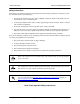
NetVanta 3200/3300/3400 Series Unit Installation The rackmount kit for the NetVanta 3448 is not included in shipments of these products. You must order the rackmount kit (P/N 1200827E1) separately. Instructions for Rack Mounting the NetVanta 3205, NetVanta 3305, NetVanta 3430, NetVanta 3448, NetVanta 3450, and NetVanta 3458 Step Action 1 To allow proper grounding, scrape the paint from the rack around the mounting holes where the NetVanta will be positioned.
Unit Installation NetVanta 3200/3300/3400 Series Instructions for Wall Mounting NetVanta 3200 Step Action 1 Decide on a location for the unit. Keep in mind that the unit needs to be mounted at or below eye level so that the LEDs are viewable. 2 Prepare the mounting surface by attaching a board (typically plywood, 3/4-inch to 1-inch thick) to a wall stud using #6 to #10 (2.5-inch or greater in length) wood screws. Important! Mounting to a stud ensures stability.
NetVanta 3200/3300/3400 Series Unit Installation Instructions for Wall Mounting NetVanta 3205/NetVanta 3305 Step Action 1 Remove the mounting ears. Rotate them 90o so that the portion of the bracket with the mounting holes is flush with the bottom of the chassis, and reattach them to the chassis (see Figure 30). 2 Decide on a location for the unit. Keep in mind that the unit needs to be mounted at or below eye level so that the LEDs are viewable.
Unit Installation NetVanta 3200/3300/3400 Series Instructions for Wall Mounting NetVanta 3430/NetVanta 3448 Step Action 1 Decide on a location for the unit. Keep in mind that the unit needs to be mounted at or below eye level so that the LEDs are viewable and enough space needs to be left on each side for the removal of the CompactFlash card and option module. 2 Attach the wallmount bracket to the bottom of the chassis using the two screws included with the shipment (see Figure 31).
NetVanta 3200/3300/3400 Series Unit Installation Instructions for Wall Mounting NetVanta 3450/NetVanta 3458 Step Action 1 Remove the mounting ears. Rotate them 90o so that the portion of the bracket with the mounting holes is flush with the bottom of the chassis, and reattach them to the chassis (see Figure 32). 2 Decide on a location for the unit. Keep in mind that the unit needs to be mounted at or below eye level so that the LEDs are viewable.
Unit Installation NetVanta 3200/3300/3400 Series Instructions for Wall Mounting the NetVanta PoE Power Supply Step Action 1 Decide on a location for the power supply. Keep in mind that the power supply needs to be mounted close enough to the NetVanta unit for the cords to reach the receptacles. 2 Prepare the mounting surface by attaching a board (typically plywood, 3/4-inch to 1-inch thick) to a wall stud using #6 to #10 (2.5-inch or greater in length) wood screws.
NetVanta 3200/3300/3400 Series Unit Installation Supplying Power to the Unit As shipped, each NetVanta 3200/3300/3400 Series is set to factory default conditions. After installing the base unit and any option modules, the NetVanta is ready to be powered. To power the unit, ensure that the unit is properly connected to an appropriate power source (as outlined in the sections that follow).
Unit Installation NetVanta 3200/3300/3400 Series Powering the NetVanta 3205 (AC), NetVanta 3305, NetVanta 3430, NetVanta 3448, NetVanta 3450, and NetVanta 3458 The AC-powered NetVanta 3205, NetVanta 3305, NetVanta 3430, NetVanta 3448, NetVanta 3450, and NetVanta 3458 come equipped with an auto-sensing 100 to 250 VAC, 50/60 Hz power supply for connecting to the proper power receptacle. A grounded, three-plug detachable cable is included with the shipment.
NetVanta 3200/3300/3400 Series Unit Installation Instructions for Powering the NetVanta with Octal PoE Upgrade Step Action 1 Plug the 2-pin connector from the PoE Power Supply into the PoE receptacle on the rear panel of the NetVanta unit. 2 Plug the PoE Power Supply’s power cord into the receptacle on the power supply. 3 Connect the 3-prong plug of the PoE Power Supply’s power cord to the proper receptacle.
Unit Installation NetVanta 3200/3300/3400 Series To comply with GR-1089-CORE, Issue 3, this equipment must be installed ONLY in a DC-C (common) bonding and grounding environment. It must NOT be utilized in a DC-I (isolated) bonding and grounding environment.
NetVanta 3200/3300/3400 Series Unit Installation Instructions for Connecting DC Power Source to the NetVanta 3205 Step Action For +24 VDC operation: 1 Connect the negative terminal of the +24 VDC power source to the negative terminal of the NetVanta 3205 DC power connector located on the rear of the unit. (See Figure 35 on page 72.) 2 Connect the negative terminal of the +24 VDC power source to the chassis ground of the +24 VDC power source.
Unit Installation NetVanta 3200/3300/3400 Series Installing Dial Backup and Network Interface Modules The DIMs plug onto the NIMs. The NIMs are then installed in the rear panel option module slot. The following tables list the installation steps. Also, see Figure 36 on page 74 and Figure 37 on page 75. For NetVanta modules with outside plant connections, ensure that all cables are removed from the module before installing or removing it from the NetVanta chassis.
NetVanta 3200/3300/3400 Series Unit Installation Instructions for Installing the NIMs Step Action 1 Remove power from the unit. 2 Remove the cover from the option slot. 3 Slide the option module into the option slot until the module is firmly seated against the chassis. 4 Secure the pins at both edges of the module. 5 Connect the cables to the associated device(s). 6 Restore power to the unit. WAN-T1 DSX-1 DBU Figure 37.
Unit Installation NetVanta 3200/3300/3400 Series Using a USB Cellular Modem with the NetVanta USB WWAN NIM The NetVanta USB WWAN NIM contains a Type A USB connector that supports a variety of third-party USB cellular modems. Visit the NetVanta USB WWAN NIM product page at http://www.adtran.com for a list of supported third-party USB cellular modems. • • Always remove power from the unit prior to removing or installing a module. Improper installation may result in damage to the modules.
NetVanta 3200/3300/3400 Series Unit Installation Installing the NetVanta VPN Accelerator Card (included in P/N 4200368L1) The optional VPN Accelerator Card plugs into a 32-bit PCI slot and is designed to be used in the NetVanta 3305 to provide encryption/decryption and security acceleration services. The card provides the following security services to the host processor: DES, triple-DES (3DES), AES, SHA-1, MD5, and random number generation.
Unit Installation NetVanta 3200/3300/3400 Series Installing SODIMM for Expandable Memory The NetVanta 3430 ships with a 144-pin, 128 MB SODIMM (P/N 1200828G1) installed. It can be upgraded to provide a maximum of 512 MB of memory using the 144-pin, 512 MB SODIMM (P/N 1200829G1). The NetVanta 3448 ships with a 200-pin, 128 MB SODIMM (P/N 1200812E1) installed.
NetVanta 3200/3300/3400 Series Unit Installation Figure 39. SODIMM Installation – Keyed Slots Figure 40. SODIMM Installation – Applying Pressure Figure 41. SODIMM Installation – Rotating the Module Downward 61200860L1-34AB Copyright © 2012 ADTRAN, Inc.
Unit Installation NetVanta 3200/3300/3400 Series Installing a CompactFlash Card The CompactFlash slot supports only ADTRAN-provided 1 GB CompactFlash cards (P/N 1200819E1). Follow these instructions when installing a card. The CompactFlash card is hot-swappable and can be inserted or removed while power is applied to the unit. Instructions for Installing a CompactFlash Card Step Action Slide the module into the CompactFlash slot until the card is firmly seated against the chassis.
NetVanta 3200/3300/3400 Series Unit Installation Installing the Octal PoE Upgrade Module The NetVanta Octal PoE Upgrade provides the ability to detect attached PDs and deliver 48 VDC to the PDs via existing CAT 5 cabling. If your NetVanta 3448 or NetVanta 3458 did not originally come with PoE capability, it can be upgraded using the Octal PoE Upgrade. The Octal PoE Upgrade is shipped with the Octal PoE module, two standoffs, the Octal PoE power supply, and appropriate power cords.
Unit Installation NetVanta 3200/3300/3400 Series Figure 43. NetVanta Octal PoE Upgrade Installation Your NetVanta unit is now ready to be configured and connected to the network. For information on configuration for a specific application, refer to the configuration guides provided on the ADTRAN Support Community. For details on the command line interface (CLI), refer to the AOS Command Reference Guide. All other related documents are also available online at http://supportforums.adtran.com.
APPENDIX A. CONNECTOR PIN DEFINITIONS The following tables provide the pin assignments for the base units, network interface modules (NIMs), and dial backup interface modules (DIMs). Base Unit Pinouts Table A-1.
Appendix A. Connector Pin Definitions NetVanta 3200/3300/3400 Series Table A-3.
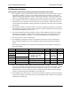
NetVanta 3200/3300/3400 Series Appendix A. Connector Pin Definitions Network Interface Module Pinouts Table A-6. WAN-DDS Connector Pinouts Pin Name Description 1 R1 Transmit data to the network–Ring 1 2 T1 Transmit data to the network–Tip 1 3-6 — Unused 7 T Receive data from the network–Tip 8 R Receive data from the network–Ring Table A-7.
Appendix A. Connector Pin Definitions NetVanta 3200/3300/3400 Series Table A-9. DSX-1 Connector Pinouts Pin Name Description 1 R Transmit data toward the DTE–Ring 2 T Transmit data toward the DTE–Tip 3 — Unused 4 R1 Receive data from the DTE–Ring 1 5 T1 Receive data from the DTE–Tip 1 6-8 — Unused Table A-10. G.
NetVanta 3200/3300/3400 Series Appendix A. Connector Pin Definitions Table A-12. WAN-ADSL Connector Pinouts Pin Name Description 1, 2 — Unused 3 R ADSL Ring 4 T ADSL Tip 5, 6 — Unused Table A-13. USB WWAN Connector Pinouts Pin Name Description 1 Vbus Provides 5 VDC power up to 1000 mA 2 D- Data 3 D+ Data 4 Ground 61200860L1-34AB Ground Copyright © 2012 ADTRAN, Inc.
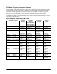
Appendix A. Connector Pin Definitions NetVanta 3200/3300/3400 Series Table A-14. Serial to Cable Connector Pinouts 90 Serial Pin V.35 Pin X.21 Pin EIA 530 Pin Name 1 P 2 2 TD_A 2 U N/A 24 ETC_A 3 Y N/A 15 TCLK_A 4 V 6 17 RCLK_A 5 R 4 3 RD_A 6 F N/A 8 DCD_A 7 H N/A 20 DTR_A 8 C 3 4 RTS_A 9 N/A 10 19 RTS_B (V.11 only) 10 N/A 12 13 CTS_B (V.
NetVanta 3200/3300/3400 Series Appendix A. Connector Pin Definitions Dial Backup Interface Module Pinouts (DBU Connector) An optional DIM is required for dial backup applications. Table A-15. Analog Modem and ISDN BRI DBU Connector Pinouts Pin Name Description 1-3 — Unused 4 R Network–Ring 5 T Network–Tip 6-8 — Unused Table A-16.
Appendix A. Connector Pin Definitions 92 NetVanta 3200/3300/3400 Series Copyright © 2012 ADTRAN, Inc.