NetVanta 4300/4400 Series Hardware Installation Guide 1202890E1 NetVanta 4305 Chassis (AC) 1200950G1 NetVanta 4305 Chassis (DC) 1700630E1 NetVanta 4430 Chassis 4200368L1 Enhanced Feature Pack (Hardware and Software) for IPsec VPN Upgrade (NetVanta 4305) 1950730G2 Enhanced Feature Pack Software for IPsec VPN Upgrade (NetVanta 4430) 1200861L1 NetVanta 56K/64K Network Interface Module 1200862L2#NEBS NetVanta T1/FT1 NEBS Network Interface Module 1202862L1 NetVanta T1/FT1 Network Interface Module
Trademarks NetVanta 4300/4400 Series Trademarks Any brand names and product names included in this manual are trademarks, registered trademarks, or trade names of their respective holders. To the Holder of the Manual The contents of this manual are current as of the date of publication. ADTRAN reserves the right to change the contents without prior notice.
NetVanta 4300/4400 Series Conventions Conventions Notes provide additional useful information. Cautions signify information that could prevent service interruption or damage to equipment. Warnings provide information that could prevent injury or endangerment to human life. 61200890E2-34R Copyright © 2013 ADTRAN, Inc.
Safety Instructions NetVanta 4300/4400 Series Safety Instructions When using your telephone equipment, please follow these basic safety precautions to reduce the risk of fire, electrical shock, or personal injury: 1. Do not use this product near water, such as a bathtub, wash bowl, kitchen sink, laundry tub, in a wet basement, or near a swimming pool. 2. Avoid using a telephone (other than a cordless type) during an electrical storm. There is a remote risk of shock from lightning. 3.
NetVanta 4300/4400 Series FCC-Required Information FCC-Required Information FCC regulations require that the following information be provided in this manual: 1. This equipment complies with Part 68 of Federal Communications Commission (FCC) rules and requirements adopted by America’s Carriers Telecommunications Association (ACTA). Each registered interface has a label that contains, among other information, a product identifier in the format US:AAAEQ##TXXXX.
FCC Radio Frequency Interference Statement NetVanta 4300/4400 Series FCC Radio Frequency Interference Statement This equipment has been tested and found to comply with the limits for a Class A digital device, pursuant to Part 15 of the FCC rules. These limits are designed to provide reasonable protection against harmful interference when the equipment is operated in a commercial environment.
NetVanta 4300/4400 Series Industry Canada Compliance Information Industry Canada Compliance Information Notice: The Industry Canada label applied to the product (identified by the Industry Canada logo or the “IC:” in front of the certification/registration number) signifies that the Industry Canada technical specifications were met. Notice: The REN for this terminal equipment is supplied in the documentation or on the product labeling/markings.
Service and Warranty 8 NetVanta 4300/4400 Series Copyright © 2013 ADTRAN, Inc.
Table of Contents Introduction . . . . . . . . . . . . . . . . . . . . . . . . . . . . . . . . . . . . . . . . . . . . . . . . . . . . . . . . . . . . . . . . . . . . . . . 15 Physical Descriptions . . . . . . . . . . . . . . . . . . . . . . . . . . . . . . . . . . . . . . . . . . . . . . . . . . . . . . . . . . . . . . . NetVanta 4305 . . . . . . . . . . . . . . . . . . . . . . . . . . . . . . . . . . . . . . . . . . . . . . . . . . . . . . . . . . . . . . . . . .
Table of Contents NetVanta 4300/4400 Series Installing the NetVanta VPN Accelerator Card (included in P/N 4200368L1) . . . . . . . . . . . . . . . . . . 54 Installing a SODIMM for Expandable Memory . . . . . . . . . . . . . . . . . . . . . . . . . . . . . . . . . . . . . . . . . . 55 Installing a CompactFlash Card . . . . . . . . . . . . . . . . . . . . . . . . . . . . . . . . . . . . . . . . . . . . . . . . . . . . . 57 Appendix A. Connector Pin Definitions. . . . . . . . . . . . . . . . . . . . . . . .
List of Figures Figure 1. Figure 2. Figure 3. Figure 4. Figure 5. Figure 6. Figure 7. Figure 8. Figure 9. Figure 10. Figure 11. Figure 12. Figure 13. Figure 14. Figure 15. Figure 16. Figure 17. Figure 18. Figure 19. Figure 20. Figure 21. Figure 22. Figure 23. Figure 24. Figure 25. Figure 26. Figure 27. NetVanta 4305 Front Panel Layout . . . . . . . . . . . . . . . . . . . . . . . . . . . . . . . . . . . . . . . . . . . . NetVanta 4305 (AC version) Rear Panel Layout . . . . . . . . . . . . . . . . . . . . .
List of Figures 12 NetVanta 4300/4400 Series Copyright © 2013 ADTRAN, Inc.
List of Tables Table 1. Table A-1. Table A-2. Table A-3. Table A-4. Table A-5. Table A-6. Table A-7. Table A-8. Table A-9. Table A-10. Table A-11. Table A-12. Table A-13. Table A-14. Table A-15. 61200890E2-34R NetVanta 4300/4400 Series LEDs . . . . . . . . . . . . . . . . . . . . . . . . . . . . . . . . . . . . . . . . . . . 10/100Base-T Ethernet Port Pinouts . . . . . . . . . . . . . . . . . . . . . . . . . . . . . . . . . . . . . . . . . 1000Base-T Gigabit Ethernet Port Pinouts. . . . . . . . . . . . .
List of Tables 14 NetVanta 4300/4400 Series Copyright © 2013 ADTRAN, Inc.
1. INTRODUCTION The NetVanta 4300/4400 Series consists of the NetVanta 4305 AC, NetVanta 4305 DC, and the NetVanta 4430. In this document, the term NetVanta 4300/4400 means all of the units collectively. If a statement only applies to one particular router, the text refers to the router individually. This hardware installation guide lists the NetVanta 4300/4400 Series units’ physical characteristics and product specifications, introduces basic functionality, and provides installation instructions.
Physical Descriptions 2. NetVanta 4300/4400 Series PHYSICAL DESCRIPTIONS NetVanta 4305 The NetVanta 4305 (AC or DC powered) is a mid-range IP router designed for medium- to large-office connectivity over Frame Relay or Point-to-Point Protocol (PPP) networks. This modular platform offers a complete solution for access routing and wide area network (WAN) connectivity in a single, compact package.
NetVanta 4300/4400 Series • • • Physical Descriptions ADSL, Annex A and Annex B SHDSL, Annex and Annex B Octal T1/E1 Wide Module (no external CSU/DSU needed) If needed, an analog modem DIM, ISDN BRI U, or ISDN BRI S/T DIM can plug onto the NIM, providing dial backup capability. Refer to Installing Dial Backup and Network Interface Modules on page 51 for more details.
Physical Descriptions NetVanta 4300/4400 Series NetVanta 4305 Front Panel Design The NetVanta 4305 front panel is shown below. Front panel LED descriptions are given in Table 1 on page 23. STATUS NET 1 WAN DBU TD RD NET 2 WAN DBU TD RD LAN 1 TD RD LNK LAN 2 TD RD LNK WIDE SLOT 1 STATUS ACTIVITY TEST NetVanta 4305 Figure 1. NetVanta 4305 Front Panel Layout NetVanta 4305 Rear Panel Design Figure 2 shows the NetVanta 4305 (AC) rear panel and Figure 3 shows the NetVanta 4305 (DC) rear panel.
NetVanta 4300/4400 Series Physical Descriptions 10/100Base-T Ethernet Interface and Activity LEDs The Ethernet ports (ETH 0/1, ETH 0/2) are RJ-45 connectors with LEDs. The yellow activity LED flashes when data traffic is being sent or received on the Ethernet port. The green link LED is on when the router has a good connection to the local area network (LAN). See Table A-1 on page 59 for the Ethernet port pinouts.
Physical Descriptions • • • • NetVanta 4300/4400 Series Mountable in a 19-inch rack Power Supply: Worldwide auto-ranging AC (120 to 240 VAC) Operating Temperature: 0°C to 50°C RoHS compliant (Telecommunications exemption) Network Interface Modules and Dial Backup Interface Modules Supported The main base unit supports a variety of interchangeable NIMs and DIMs.
NetVanta 4300/4400 Series Physical Descriptions NetVanta 4430 Domestic Shipping Contents Domestic shipments of the NetVanta 4430 include the following items: • • • NetVanta 4430 base unit with attached mounting ears Quick start guide Detachable AC power cord NetVanta 4305 International Shipping Contents International shipments of the NetVanta 4430 include the following items: • • • NetVanta 4430 base unit with attached mounting ears Quick start guide All necessary power cords Option module shipping c
Physical Descriptions NetVanta 4300/4400 Series CompactFlash The NetVanta 4430 front panel contains a CompactFlash® slot for nonvolatile configuration storage and compressed code storage. ADTRAN supports only ADTRAN-provided CompactFlash (16 MB to 1 GB) (refer to the list of part numbers on the front cover). Refer to Installing a CompactFlash Card on page 57. NetVanta 4430 Rear Panel Design Figure 5 shows the NetVanta 4430 rear panel. The chassis are shown with the T1/FT1 + DSX-1 NIM installed.
NetVanta 4300/4400 Series Physical Descriptions NetVanta 4300/4400 Series Front Panel LEDs Table 1 describes the front panel LEDs. Table 1. NetVanta 4300/4400 Series LEDs LED STATUS Color Green (flashing) Amber (solid) Off Unit is powering up. On power up, the STAT LED flashes rapidly for five seconds, during which time the user may escape to boot mode from the console port. Power is on and self-test passed. Power is on, but the self-test failed or the boot code could not be booted.
Option Modules 3. NetVanta 4300/4400 Series OPTION MODULES The NetVanta 4300/4400 Series accepts several option modules designed to meet a variety of networking requirements. The option modules are of three types: plug-in NIMs, plug-on DIMs, and a wide NIM. NIMs are cards that plug directly into the option module slot (labeled SLOT 1 NET/DBU or SLOT 2 NET/DBU), located on the rear of the base unit.
NetVanta 4300/4400 Series Option Modules Option Module Shipping Contents NetVanta 56K/64K NIM (1200861L1) Shipments of the 56K/64K NIM include the following items: • • • 56K/64K Network Interface Module Quick start guide 6-foot RJ-45 to RJ-45 cable (ADTRAN P/N 3127004) NetVanta T1/FT1 NIM (1202862L1) Shipments of the T1/FT1 NIM include the following items: • • • T1/FT1 Network Interface Module Quick start guide 15-foot RJ-45 to RJ-45 cable (ADTRAN P/N 3125M008@A) NetVanta T1/FT1 NEBS NIM (1200862L2#
Option Modules NetVanta 4300/4400 Series NetVanta E1/FE1 + G.703 Drop NIM (1200878E1/L1) Shipments of the E1/FE1 + G.703 Drop NIM include the following items: • • • E1/FE1 + G.
NetVanta 4300/4400 Series Option Modules NetVanta Analog Modem DIM (1200864L1) Shipments of the Analog Modem DIM include the following items: • • • Analog Modem Dial Backup Interface Module Quick start guide 7-foot RJ-45 to RJ-11 cable (ADTRAN P/N 3125M007@A) NetVanta ISDN BRI DIM (1200865L1) Shipments of the ISDN BRI DIM include the following items: • • • ISDN BRI Dial Backup Interface Module Quick start guide 7-foot RJ-45 to RJ-11 cable (ADTRAN P/N 3125M007@A) NetVanta ISDN S/T DIM (1200875L1) Sh
Option Modules NetVanta 4300/4400 Series Network Interface Modules NetVanta 56K/64K NIM (P/N 1200861L1) The 56K/64K NIM (shown in Figure 6) provides a WAN-DDS interface for the NetVanta 4300/4400 Series. See Table A-5 on page 61 for the WAN-DDS connector pinouts, and see Table A-14 on page 64 for the DBU connector pinouts. An optional DIM is required for dial backup applications. Figure 6.
NetVanta 4300/4400 Series Option Modules NetVanta T1/FT1 NIM (P/N 1202862L1) The T1/FT1 NIM (shown in Figure 7) provides a T1 (full T1 or fractional T1) WAN interface for the NetVanta 4300/4400 Series. See Table A-6 on page 61 for the WAN-T1 connector pinouts and see Table A-14 on page 64 for the DBU connector pinouts. An optional DIM is required for dial backup applications. WAN-T1 DBU Figure 7.
Option Modules NetVanta 4300/4400 Series NetVanta T1/FT1 NEBS NIM (P/N 1200862L2#NEBS) The T1/FT1 NEBS NIM (see Figure 8) T1 WAN interface for the NetVanta 4305 DC. The T1 NEBS NIM is NEBS Level 3 compliant, and provides a full or fractional T1 network interface. See WAN-T1 Connector Pinouts on page 61 for the WAN-T1 connector pinouts. WAN-T1 Figure 8.
NetVanta 4300/4400 Series Option Modules NetVanta T1/FT1 + DSX-1 NIM (P/N 1202863L1) The T1/FT1 + DSX-1 NIM (see Figure 9) provides a full T1 or fractional T1 network interface and a DSX-1 interface. See Table A-6 on page 61 for the WAN-T1 connector pinouts, Table A-8 on page 62 for the DSX-1 connector pinouts, and Table A-14 on page 64 for the DBU connector pinouts. An optional DIM is required for dial backup applications. WAN-T1 DSX-1 DBU Figure 9.
Option Modules NetVanta 4300/4400 Series NetVanta Dual T1 NIM (P/N 1200872L1/1202872L1) The NetVanta Dual T1 NIM (see Figure 10) provides two WAN T1 interfaces for the NetVanta 4300/4400 Series. The module provides up to 2.048 Mbps on each network interface. See Table A-6 on page 61 for the pinouts. See Table A-14 on page 64 for the DBU connector pinouts. An optional DIM is required for dial backup applications. WAN T1/1 WAN T1/2 DBU Figure 10.
NetVanta 4300/4400 Series Option Modules NetVanta Octal T1/E1 Wide Module (P/N 1202843E1) The NetVanta Octal T1/E1 Wide Module second generation (shown in Figure 11) provides eight T1 or E1 interfaces with RJ-45 wire connections. These interfaces can be used independently or as aggregate bandwidth using Multilink PPP Protocol (MLPPP). Table A-6 on page 61 and Table A-7 on page 61 give the pinouts for this module. Figure 11.
Option Modules NetVanta 4300/4400 Series Clock Source • • Network Internal Diagnostics • • Network Loopbacks: Line, payload, remote Test Pattern Generation and Detection: QRSS, 215 - 1, 511, all ones, all zeros Compliance • • • • • • • • • • EMC - see Electromagnetic Compatibility (EMC) Table on page 6.
NetVanta 4300/4400 Series Option Modules NetVanta E1/FE1 NIM (P/N 1200868E1/L1) The NetVanta E1/FE1 NIM (see Figure 12) provides a WAN-E1 interface for the NetVanta 4300/4400 Series meeting the requirements of ITU-T G.703/G.704. The module provides a single 2.048 Mbps network interface. See Table A-7 on page 61 for the pinouts. See Table A-14 on page 64 for the DBU connector pinouts. An optional DIM is required for dial backup applications. WAN-E1 DBU Figure 12.
Option Modules NetVanta 4300/4400 Series NetVanta E1/FE1 + G.703 Drop NIM (P/N 1200878E1/L1) The NetVanta E1/FE1 + G.703 Drop NIM (see Figure 13) provides a single WAN-E1 interface (2.043 Mbps) with user-selectable TS0 assignment and a G.703 drop port, which may be used to drop and insert traffic to an E1 PBX. See Table A-7 on page 61 for the E1 pinouts. See Table A-9 on page 62 for the G.703 pinouts. See Table A-14 on page 64 for the DBU connector pinouts.
NetVanta 4300/4400 Series Option Modules NetVanta Serial NIM (P/N 1200866E1) The NetVanta Serial NIM (shown in Figure 14) can be configured by the user as a V.35, an X.21 (V.11), or an EIA 530 interface. This module supports rates up to a maximum of 10 Mbps. An additional V.35 (ADTRAN P/N 1200873L1), X.21 (ADTRAN P/N 1200874L1), or EIA 530 (P/N 1200883L1) cable is required (see Caution below).
Option Modules NetVanta 4300/4400 Series NetVanta ADSL NIM, Annex A (P/N 1202869E1) The NetVanta ADSL, Annex A (see Figure 15) adds ADSL capability to the NetVanta 4300/4400 Series. The module provides a single ADSL, ADSL2, or ADSL2+ network interface to support rates up to 25 Mbps. See Table A-10 on page 62 for the pinouts. See Table A-14 on page 64 for the DBU connector pinouts. An optional DIM is required for dial backup applications. WAN-ADSL DBU Figure 15.
NetVanta 4300/4400 Series Option Modules NetVanta ADSL NIM, Annex B (P/N 1202889E1) The NetVanta ADSL, Annex B (see Figure 16) adds ADSL capability to the NetVanta 4300/4400 Series. The module provides a single 2.048 Mbps network interface. See Table A-10 on page 62 for the pinouts. See Table A-14 on page 64 for the DBU connector pinouts. An optional DIM is required for dial backup applications. WAN-ADSL DBU Figure 16.
Option Modules NetVanta 4300/4400 Series NetVanta SHDSL NIM, Annex A (P/N 1200936E1) The NetVanta SHDSL NIM, Annex A (shown in Figure 17) provides a WAN-SHDSL interface for the NetVanta 4000 Series. See Table A-11 on page 62 for the SHDSL connector pinouts. WAN-SHDSL ANNEX A Figure 17. NetVanta SHDSL NIM, Annex A Features and Specifications Operating Mode Diagnostics • • • • • Line termination (CO) Network termination (CPE) G.SHDSL Interface • • • • • • Supported Standards: ITU-T G.991.
NetVanta 4300/4400 Series Option Modules NetVanta SHDSL NIM, Annex B (P/N 1200937E1) The NetVanta SHDSL NIM, Annex B (shown in Figure 18) provides a WAN-SHDSL interface for the NetVanta 4000 Series. See Table A-11 on page 62 for the SHDSL connector pinouts. WAN-SHDSL ANNEX B Figure 18. NetVanta SHDSL NIM, Annex B Features and Specifications Operating Mode Diagnostics • • • • • Line termination (CO) Network termination (CPE) G.SHDSL Interface • • • • • • Supported Standards: ITU-T G.991.
Option Modules NetVanta 4300/4400 Series NetVanta USB WWAN NIM (P/N 1702803F1) The NetVanta USB WWAN NIM (shown in Figure 19) provides a USB interface for the NetVanta 4430 only. For specific connection and configuration instructions, refer to the NetVanta USB WWAN NIM Quick Start Guide or the USB WWAN NIM and the Cellular Interface Configuration Guide available on ADTRAN’s Support Forum (https://supportforums.adtran.com). See Table A-12 on page 63 for the USB WWAN connector pinouts. WWAN Figure 19.
NetVanta 4300/4400 Series Option Modules Dial Backup Interface Modules NetVanta Analog Modem DIM (P/N 1200864L1) The Analog Modem DIM provides a modem with data rates up to 33.6 kbps. This DIM is a plug-on card that connects to the NIM. For installation instructions, refer to Installing Dial Backup and Network Interface Modules on page 51. Features and Specifications Features • • ITU V.90 compliant Async Compliance • • • • EMC - see Electromagnetic Compatibility (EMC) Table on page 6.
Option Modules NetVanta 4300/4400 Series NetVanta ISDN BRI DIM (P/N 1200865L1) The NetVanta ISDN BRI DIM provides dial backup access to the public switched telephone network (PSTN) via Basic Rate ISDN. This DIM is a plug-on module that connects to the NIM. For installation instructions, refer to Installing Dial Backup and Network Interface Modules on page 51.
NetVanta 4300/4400 Series Option Modules NetVanta ISDN S/T DIM (P/N 1200875L1) The NetVanta ISDN S/T DIM provides dial backup access to the PSTN via Basic Rate ISDN. This DIM is a plug-on module that connects to the NIM. For installation instructions, refer to Installing Dial Backup and Network Interface Modules on page 51.
Unit Installation 4. NetVanta 4300/4400 Series UNIT INSTALLATION The instructions and guidelines provided in this section cover hardware installation topics, such as wall mounting/rack mounting the unit and installing option cards.
NetVanta 4300/4400 Series Unit Installation Tools Required The following customer-provided tools are required for the hardware installation of the NetVanta 4300/ 4400 Series: • • • • • • Ethernet cable Network cable (module dependent) DSX-1 cable (T1/FT1 + DSX-1 module only) G.703 cable (E1/FE1 + G.
Unit Installation NetVanta 4300/4400 Series Instructions for Rack Mounting the NetVanta Step Action 1 Position the NetVanta in a stationary equipment rack. This unit occupies 1U of space. To allow proper grounding, scrape the paint from the rack around the mounting holes where the NetVanta will be positioned. 2 Have an assistant hold the unit in position as you install two mounting bolts through the unit’s brackets and into the equipment rack using a #2 Phillips-head screwdriver.
NetVanta 4300/4400 Series Unit Installation Figure 20. Wall Mounting the Unit Supplying Power to the Unit As shipped, each NetVanta 4000 is set to factory default conditions. After installing the base unit and any option modules, the NetVanta 4000 is ready for power up. To power the unit, ensure that the unit is properly connected to an appropriate power source (as outlined in the sections below).
Unit Installation NetVanta 4300/4400 Series NetVanta 4305 (DC) The DC-powered NetVanta 4305 connects to a centralized DC power source via the four-position power connector on the rear of the chassis (see Figure 3 on page 18). The nominal input of the NetVanta 4305 is +24 VDC or -48 VDC. Power and ground connections require copper conductors and a ring lug.
NetVanta 4300/4400 Series Unit Installation Installing Dial Backup and Network Interface Modules The DIMs plug onto the NIMs. The NIMs are then installed in the rear panel option module slot. The following tables list the installation steps. See Figure 21 on page 51 below and Figure 22 on page 52. For NetVanta modules with outside plant connections, ensure that all cables are removed from all modules before installing or removing it from the NetVanta chassis.
Unit Installation NetVanta 4300/4400 Series Instructions for Installing the NIMs and Wide NIMs Step Action 1 Remove power from the unit. 2 Remove the cover plate from the appropriate option slot on the rear panel of the unit. 3 Slide the option module into the option slot until the module is firmly seated against the chassis. 4 Secure the pins at both edges of the module. 5 Connect the cables to the associated device(s). 6 Restore power to the unit.
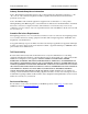
NetVanta 4300/4400 Series Unit Installation Using a USB Cellular Modem with the NetVanta USB WWAN NIM The NetVanta USB WWAN NIM contains a Type A USB connector that supports a variety of third-party USB cellular modems. Visit the NetVanta USB WWAN NIM product page at www.adtran.com for a list of supported third-party USB cellular modems. • • Always remove power from the unit prior to removing or installing a module. Improper installation may result in damage to the modules.
Unit Installation NetVanta 4300/4400 Series Installing the NetVanta VPN Accelerator Card (included in P/N 4200368L1) The optional VPN Accelerator Card plugs into a 32-bit PCI slot and is designed to be used in the NetVanta 4305 to provide encryption/decryption and security acceleration services. The card provides the following security services to the host processor: DES, triple-DES (3DES), AES, SHA-1, MD5, and random number generation.
NetVanta 4300/4400 Series Unit Installation Installing a SODIMM for Expandable Memory The NetVanta 4430 ships with a 200-pin, 256 MB SODIMM (P/N 1200813E1) installed. It can be upgraded to provide 512 MB using the 200-pin, 512 MB SODIMM (P/N 1200814E1). Follow these instructions to install a SODIMM module. • • • SODIMMs are intended to be installed only by qualified service personnel. There are three types of SODIMM memory modules used by ADTRAN: 200-pin DDR1, 200-pin DDR2, and 144-pin DDR2.
Unit Installation NetVanta 4300/4400 Series Figure 24. SODIMM Installation – Keyed Slots Figure 25. SODIMM Installation – Applying Pressure Figure 26. SODIMM Installation – Rotating the Module Downward 56 Copyright © 2013 ADTRAN, Inc.
NetVanta 4300/4400 Series Unit Installation Installing a CompactFlash Card The CompactFlash slot supports only ADTRAN-provided 1 GB CompactFlash cards. Follow these instructions when installing a card. The CompactFlash card is hot-swappable and can be inserted or removed while power is applied to the unit. Instructions for Installing a CompactFlash Card Step Action Slide the module into the CompactFlash slot until the card is firmly seated against the chassis.
Unit Installation 58 NetVanta 4300/4400 Series Copyright © 2013 ADTRAN, Inc.
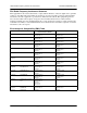
APPENDIX A. CONNECTOR PIN DEFINITIONS The following tables provide the pin assignments for the base unit, network interface modules (NIMs), and dial backup interface modules (DIMs). Base Unit Pinouts Table A-1. 10/100Base-T Ethernet Port Pinouts Pin Name Description 1 TX1 Transmit Positive 2 TX2 Transmit Negative 3 RX1 Receive Positive 4, 5 — 6 RX2 7, 8 — Unused Receive Negative Unused Table A-2.
NetVanta 4300/4400 Series Table A-3. SFP Slot Pinouts Pin Name Pin Name 1 TGND 11 RGND 2 TX FAULT 12 RX- 3 TX DISABLE 13 RX+ 4 MOD DEF(2) 14 RGND 5 MOD DEF(1) 15 VccR 6 MOD DEF(0) 16 VccT 7 RATE SELECT 17 TGND 8 LOS 18 TX+ 9 RGND 19 TX- 10 RGND 20 TGND Table A-4.
NetVanta 4300/4400 Series Network Interface Module Pinouts Table A-5. WAN-DDS Connector Pinouts Pin Name Description 1 R1 Transmit data to the network–Ring 1 2 T1 Transmit data to the network–Tip 1 3-6 — Unused 7 T Receive data from the network–Tip 8 R Receive data from the network–Ring Table A-6.
NetVanta 4300/4400 Series Table A-8. DSX-1 Connector Pinouts Pin Name Description 1 R Transmit data toward the DTE–Ring 2 T Transmit data toward the DTE–Tip 3 — Unused 4 R1 Receive data from the DTE–Ring 1 5 T1 Receive data from the DTE–Tip 1 6-8 — Unused Table A-9. G.
NetVanta 4300/4400 Series Table A-12. USB WWAN Connector Pinouts Pin Name Description 1 Vbus Provides 5 VDC power up to 1000 mA 2 D- Data 3 D+ Data 4 Ground Ground Table A-13. Serial to Cable Pinouts Serial Pin V.35 Pin X.21 Pin EIA 530 Pin Name 1 P 2 2 TD_A 2 U N/A 24 ETC_A 3 Y N/A 15 TCLK_A 4 V 6 17 RCLK_A 5 R 4 3 RD_A 6 F N/A 8 DCD_A 7 H N/A 20 DTR_A 8 C 3 4 RTS_A 9 N/A 10 19 RTS_B (V.11 only) 10 N/A 12 13 CTS_B (V.
NetVanta 4300/4400 Series Dial Backup Interface Module Pinouts (DBU Connector) An optional DIM is required for dial backup applications. Table A-14. Analog Modem and ISDN BRI DBU Connector Pinouts Pin Name Description 1-3 — Unused 4 R Network–Ring 5 T Network–Tip 6-8 — Unused Table A-15.