NxT1 HSSI/V.
901 Explorer Boulevard P.O. Box 140000 Huntsville, AL 35814-4000 (256) 963-8000 © 2002 ADTRAN, Inc. All Rights Reserved. Printed in U.S.A.
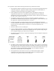
Notes provide additional useful information. Cautions signify information that could prevent service interruption. Warnings provide information that could prevent damage to the equipment or endangerment to human life. Safety Instructions When using your telephone equipment, please follow these basic safety precautions to reduce the risk of fire, electrical shock, or personal injury: 1.
Affidavit Requirements for Connection to Digital Services • • • An affidavit is required to be given to the telephone company whenever digital terminal equipment without encoded analog content and billing protection is used to transmit digital signals containing encoded analog content which are intended for eventual conversion into voiceband analog signals and transmitted on the network.
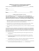
Affidavit for Connection of Customer Premises Equipment to 1.544 Mbps and/or Subrate Digital Services For the work to be performed in the certified territory of ___________________ (telco name) State of ________________ County of ________________ I, _______________________ (name), ____________________________________ (business address), ____________________ (telephone number) being duly sworn, state: I have responsibility for the operation and maintenance of the terminal equipment to be connected to 1.
I agree to provide ______________________ (telco’s name) with proper documentation to demonstrate compliance with the information as provided in the preceding paragraph, if so requested.
FCC regulations require that the following information be provided in this manual: 1. This equipment complies with Part 68 of FCC rules. On the back of the equipment housing is a label showing the FCC registration number and ringer equivalence number (REN). If requested, provide this information to the telephone company. 2. If this equipment causes harm to the telephone network, the telephone company may temporarily discontinue service.
Federal Communications Commission Radio Frequency Interference Statement This equipment has been tested and found to comply with the limits for a Class A digital device, pursuant to Part 15 of the FCC Rules. These limits are designed to provide reasonable protection against harmful interference when the equipment is operated in a commercial environment.
Industry Canada Compliance Information Notice: The Industry Canada label applied to the product (identified by the Industry Canada logo or the “IC:” in front of the certification/registration number) signifies that the Industry Canada technical specifications were met. Notice: The Ringer Equivalence Number (REN) for this terminal equipment is supplied in the documentation or on the product labeling/markings.
Warranty and Customer Service ADTRAN will replace or repair this product within five years from the date of shipment if it does not meet its published specifications or fails while in service. For detailed warranty, repair, and return information refer to the ADTRAN Equipment Warranty and Repair and Return Policy Procedure. Return Material Authorization (RMA) is required prior to returning equipment to ADTRAN.
Customer Service, Product Support Information, and Training ADTRAN will repair and return this product if within five years from the date of shipment the product does not meet its published specification or the product fails while in service. A return material authorization (RMA) is required prior to returning equipment to ADTRAN. For service, RMA requests, training, or more information, use the contact information given below.
Post-Sale Support Your reseller should serve as the first point of contact for support. If additional support is needed, the ADTRAN Support web site provides a variety of support services such as a searchable knowledge base, updated firmware releases, latest product documentation, service request ticket generation and trouble-shooting tools. All of this, and more, is available at: http://support.adtran.com When needed, further pre-sales assistance is available by calling our Technical Support Center.
Table of Contents List of Tables.......................................................................................................................................................15 List of Figures .....................................................................................................................................................17 Chapter 1 Introduction................................................................................................................................
Table of Contents T1 Menus .............................................................................................................................................. 33 IMUX Menus ....................................................................................................................................... 35 HSSI Menus .........................................................................................................................................
List of Tables Table 2-1. Table 2-2. Table 3-1. T1 Pinout Connection ...................................................................................................................25 HSSI/V.35 (SCSI-50) Pinout ........................................................................................................25 Menu Tree for NxT1 HSSI/V.35 Modules Menu .....................................................................29 61200771L1-1 NxT1 HSSI/V.
List of Tables 16 NxT1 HSSI/V.
List of Figures Figure 1-1. Figure 1-2. Figure 2-1. Figure 3-1. Figure 3-2. Figure 3-3. Figure 3-4. Figure A-1. NxT1 HSSI/V.35 System ..............................................................................................................19 NxT1 HSSI/V.35 Option Module ...............................................................................................22 Installing the NxT1 HSSI/V.35 Module.....................................................................................24 Modules Menu.
List of Figures 18 NxT1 HSSI/V.
Chapter 1 Introduction NXT1 HSSI/V.35 MODULE OVERVIEW The NxT1 HSSI/V.35 Module is a member of the ATLAS 800 family of integrated access products that supports aggregating point-to-point T1 bandwidth (from 2 to 8 T1s) to a single logical datastream available on the high speed serial interface (HSSI) of the module. The HSSI interface is delivered using a standard 50-pin SCSI-II connector.
Chapter 1. Introduction When combined with the supported ATLAS 800 Series base units and, optionally, one or more Quad T1/PRI or T3 Modules, the NxT1 HSSI/V.35 Module can implement high-speed point-to-point connectivity), combining multiple T1 circuits into one logical channel on the HSSI/V.35 interface. FUNCTIONAL DESCRIPTION The NxT1 HSSI/V.35 Module installs in any available option slot in the supported ATLAS 800 Series units.
Chapter 1. Introduction Tests Line or payload loopback (Local and Remote) Connectors RJ-48C The HSSI port of the NxT1 HSSI/V.35 Module conforms to the following specifications: Line Rate Up to 11.04 Mbps T1 Links 1 to 8 Total T1 Links (in any combination of module T1 interfaces and other T1/T3 modules) Connector 50 pin SCSI-II Female The V.35 interface of the NxT1 HSSI/V.35 Module (using the optional adapter cable) conforms to the following specifications: Line Rate Up to 5.
Chapter 1. Introduction PHYSICAL DESCRIPTION The NxT1 HSSI/V.35 Module (see Figure 1-2) plugs into any available option slot in the rear of the supported ATLAS 800 Series units. T1-1 T1-2 T1-3 T1-4 HSSI/V.35 NxT1 HSSI/V.35 ATLAS 800 SERIES Figure 1-2. NxT1 HSSI/V.35 Option Module The label over each RJ-48C connector refers to the port on the NxT1 HSSI/V.35 Module. 22 NxT1 HSSI/V.
Chapter 2 Installation BEFORE INSTALLING THE NXT1 HSSI/V.35 MODULE Carefully unpack and inspect the NxT1 HSSI/V.35 Module for shipping damages. If you suspect damage occurred during shipping, file a claim immediately with the carrier and then contact ADTRAN Technical Support (see the front pages of this manual for pertinent information). If possible, keep the original shipping container for returning the NxT1 HSSI/V.35 Module for repair or for verification of shipping damage.
Chapter 2. Installation INSTALLING THE NXT1 HSSI/V.35 MODULE Figure 2-1 represents the actions required to properly install the NxT1 HSSI/V.35 Module, as described in the Step/Action table below. T1-1 T1-2 T1-3 T1-4 HSSI/V.35 800 SERIES NxT1 HSSI/V.35 ATLAS Figure 2-1. Installing the NxT1 HSSI/V.35 Module Instructions for Installing the NxT1 HSSI/V.35 Module Step Action 1 Remove the cover plate from the appropriate option slot in the ATLAS 800 Series chassis rear panel.
Chapter 2. Installation WIRING Each module T1 port uses a single RJ-48C jack to connect to a T1 circuit. Table 2-1 shows the T1 pinout connection. The required wiring connection follows: (USOC) RJ-48C Connector Type Table 2-1. T1 Pinout Connection PIN NAME DESCRIPTION 1 R1 RXDATA Receive data from the network ring 2 T1 RXDATA Receive data from the network tip 3, 6, 7, 8 Unused n/ a 4 R TXDATA Send data towards the network ring 5 T TXDATA Send data towards the network tip The HSSI/V.
Chapter 2. Installation Table 2-2. HSSI/V.35 (SCSI-50) Pinout (Continued) PIN (+ side) PIN (- side) DIRECTION DESCRIPTION — 39 — Ancillary to DCE (Reserved) 14 — I V.35 RTS - Request to Send 15 40 I V.35 TT Terminal Timing 16 41 I V.35 SD Send Data — 42 O V.35 DCD - Data Carrier Detect 17-18 43 — Ancillary to DCE (Reserved) 19 44 — HSSI SG - Signal Ground 20 45 O V.35 ST - Send Timing 21 46 O V.35 RT - Receive Timing 22 47 O V.35 RD - Receive Data 23 — O V.
Chapter 3 Operation OVERVIEW You can control and configure the NxT1 HSSI/V.35 Module from a variety of sources, including the following: • • • The ATLAS 800 Series front panel, providing minimal configuration and status support The terminal menus, allowing detailed configuration, status, and diagnostics SNMP, primarily for reporting alarm conditions and system status The remainder of this section describes the menu items presented when managing the NxT1 HSSI/V.35 Module via the terminal menu.
Chapter 3. Operation MODULES The ATLAS 800 Series system controller automatically detects the presence of the NxT1 HSSI/V.35 Module when it is installed in the system. To see the menus for the NxT1 HSSI/V.35 Module via the terminal menu, use the arrow keys to scroll to the Modules menu and press ENTER to access the module choices. Figure 3-1 shows the Modules menu (see also the menu tree in Table 3-1 on page 29). The following sections describe all the Modules’ menu options. Figure 3-1.
Chapter 3.
Chapter 3. Operation installing modules by simply specifying the module that you want to install in each slot. TYPE automatically displays the name of an installed module. If you want to change this field to a different type of module, you must set TYPE to EMPTY before selecting the other module. MENU Displays additional status and configuration menus for the selected module.
Chapter 3. Operation EMPTY The system controller has not detected the presence of a module in the slot, nor has a module been manually enabled for this option slot. OFFLINE The module is installed, but has been taken offline by a user. The module is still responding to controller polls. OFFLINE/NO RESPONSE The module is installed, but has been taken offline by a user. The module is not responding to polls. REV This read-only field displays the hardware revision of the NxT1 HSSI/V.35 Module.
Chapter 3. Operation NXT1 HSSI OPTION MODULE The NxT1 HSSI/V.35 Module system controller automatically detects the presence of the NxT1 HSSI Option Module when it is installed in the system (listed as NXT1 HSSI). To see the menus for the NxT1 HSSI Option Module via the terminal menu, use the arrow keys to scroll to the MODULES menu and press to access the module choices. V.35 is available when using the optional adapter cable (ADTRAN P/N 3125I081).
Chapter 3. Operation T1 MENUS Read Security: 5 Provides information about the four T1 interfaces located on the NxT1 HSSI Option Module. This menu is only visible when T1 ENABLE is set to ENABLED. ALARMS Read security: 5 Displays an alarm condition on the ATLAS 550 unit. Press to access this menu item. LOS Indicates a loss of signal detected on port interface. RED Indicates inability to frame data received on the port. Alternately referred to as Out of Frame (OOF).
Chapter 3. Operation SES Severely Errored Second (SES) is a second with 320 or more error events OR one or more Out Of Frame events SEFS Severely Errored Frame Second is a second that contains four consecutive errored framing patterns. LOFC Loss of Frame Count is a count of seconds in which a valid framing pattern could not be obtained.
Chapter 3. Operation TX PRM Controls the sending of performance report messaging (PRM) data on the facility data link (FDL). The PRM data continues to be collected even if XMIT PRM is turned off (possible only with ESF format). Choose either ON or OFF. LBO Write security: 2; Read security: 5 Selects the Line Build Out (LBO) for the network interface. The LBO setting determines the amplitude of the transmitted signal. For short haul (intra-building) applications, choose from the ft options.
Chapter 3. Operation CONFIG Read Security: 5; Write Security: 5 Contains parameters to include T1 data streams to the HSSI interface. PRT Displays the port number for the T1s mapped to the NxT1 HSSI interface. Ports 1 through 4 are the T1 interfaces located on the NxT1 HSSI Option Module. Ports 5 through 8 are T1s mapped to the NxT1 HSSI Option Module in the Dedicated Maps. GROUP ASSOCIATION Associates T1s (either mapped to this card and/or the on-board T1s) with the HSSI interface data stream.
Chapter 3. Operation Remote Line Loopback Local Line Loopback Local DTE Loopback NxT1 HSSI T1 Interfaces IMUX DTE Figure 3-4. HSSI Interface Loopback Test Diagram LA AND LB (Not applicable in V.35 mode.) Displays the status of the loopback circuit A and B signals. LA and LB are asserted by the DTE to enable a loopback on the DCE and its associated data communications channel.
Chapter 3. Operation RX RATE AND TX RATE Displays the current average receive and transmit data rate on the HSSI interface. CONFIG Read Security: 5 Provides configuration parameters for the HSSI interface including data clocking. When using the NxT1 HSSI/V35 Module in V.35 mode, Data Set Ready (DSR) and Data Carrier Detect (DCD) are always active. TX CLOCK Controls the clock used by the NxT1 HSSI/V.35 Module to accept the transmit (TX) data from the DTE. This is usually set to Normal.
Chapter 3. Operation ATLAS FEATURES USED WITH NXT1 HSSI/V.35 MODULE OPTIONS Two additional ATLAS 800 Series menu items can operate in conjunction with the NxT1 HSSI/V.35 Module: FACTORY RESTORE and RUN SELFTEST. FACTORY RESTORE You can restore the factory default settings for an NxT1 HSSI/V.
Chapter 3. Operation 40 NxT1 HSSI/V.
Appendix A Dedicated Maps Configuration The DEDICATED MAPS menu assigns dedicated connections between any two ports in the ATLAS 800 Series Base Unit. This section describes the DEDICATED MAPS menu items (see Figure A-1). These options are moduledependent; that is, the menu items available depend on the module selected. Figure A-1. Dedicated Maps Menu ACTIVATE MAP Write security:3; Read security:5 Activates a dedicated map—automatically or manually.
Appendix A. Dedicated Maps Configuration CURRENT MAP Read security:5 Displays the name of the currently active dedicated map (read only). CREATE/EDIT MAPS Write security:3; Read security:5 Creates new maps and defines settings, as well as edits existing maps. To add a new map, position the cursor in the index column and press . NxT1 HSSI/V.35 Module automatically names the maps in the sequence in which they are created. You can change the names with MAP NAME.
Appendix A. Dedicated Maps Configuration TO SLOT Write security:3; Read security:5 Specifies the slot to use for the second end of a connection. Select this option, and a list of all of the slots and the modules installed in the slots displays. Pick the appropriate slot and press . PORT Write security:3; Read security:5 Specifies the port to use for the second end of a connection. When you select this option, a list of ports and module types appears.
Appendix A. Dedicated Maps Configuration NXT1 HSSI OPTION MODULE CONNECTS Write Security: 3; Read Security: 5 Enters the dedicated map connections. Press to activate the submenus. The NxT1 HSSI/V35 Module supports connects from the module’s four built-in T1 ports as well as other installed T1/T3 modules.
Appendix A. Dedicated Maps Configuration S This DS0 is used in the switched DIAL PLAN and conflicts with this connection. N This DS0 is already used in this DEDICATED MAP. N This DS0 is already used in this DEDICATED MAP and conflicts with this connection. T1 TROUBLE CODE SERVICE Sets known values in the signaling bits and the data field for outgoing DS0s which are cross-connected to a T1 port experiencing alarms. The trunk conditioning process consists of a 2.
Appendix A. Dedicated Maps Configuration 46 NxT1 HSSI/V.
Index A Menu Tree . . . . . . . . . . . . . . . . . . . . . . . . . . . . . . 29 Accessing the unit . . . . . . . . . . . . . . . . . . . . . . . . 27 Alarms Operation . . . . . . . . . . . . . . . . . . . . . . . . . . . 26 Application . . . . . . . . . . . . . . . . . . . . . . . . . . . . . 19 D Dedicated Maps NxT1 HSSI Module . . . . . . . . . . . . . . . . . . . 44 Overview . . . . . . . . . . . . . . . . . . . . . . . . . . . . 41 P Physical Description . . . . . . . . . . . . . . . . . . . . . .
Index Index-48 NxT1 HSSI/V.