NetVanta 6310/6330 Series Hardware Installation Guide 1702100G1 61700100G1-34F June 2013 NetVanta 6310 47006332G1 NetVanta 6330 (8 FXS) 47006334G1 NetVanta 6330 (16 FXS) 47006336G1 NetVanta 6330 (24 FXS) 47006337G1 NetVanta 6330 (16 FXS/8 FXO) 1700101G1 NetVanta SHDSL, Annex A NIM2 1700101G2 NetVanta SHDSL Annex B NIM2 1700102G1 NetVanta Quad FXS VIM2 1700103G1 NetVanta Quad SHDSL EFM, Annex A NIM2 1700103G2 NetVanta Quad SHDSL EFM, Annex B NIM2 1700105G1 NetVanta Quad FXO VIM2 170010
Trademarks NetVanta 6310/6330 Series Hardware Installation Guide Trademarks Any brand names and product names included in this manual are trademarks, registered trademarks, or trade names of their respective holders. To the Holder of the Manual The contents of this manual are current as of the date of publication. ADTRAN reserves the right to change the contents without prior notice.
NetVanta 6310/6330 Series Hardware Installation Guide Conventions Conventions Notes provide additional useful information. Cautions signify information that could prevent service interruption or damage to the equipment. Warnings provide information that could prevent injury or endangerment to human life. 61700100G1-34F Copyright © 2013 ADTRAN, Inc.
Safety Instructions NetVanta 6310/6330 Series Hardware Installation Guide Safety Instructions When using your telephone equipment, please follow these basic safety precautions to reduce the risk of fire, electrical shock, or personal injury: 1. Do not use this product near water, such as a bathtub, wash bowl, kitchen sink, laundry tub, in a wet basement, or near a swimming pool. 2. Avoid using a telephone (other than a cordless type) during an electrical storm.
NetVanta 6310/6330 Series Hardware Installation Guide FCC-Required Information FCC-Required Information FCC regulations require that the following information be provided in this manual: 1. This equipment complies with Part 68 of Federal Communications Commission (FCC) rules and requirements adopted by America’s Carriers Telecommunications Association (ACTA). Each registered interface has a label that contains, among other information, a product identifier in the format US:AAAEQ##TXXXX.
FCC Radio Frequency Interference Statement NetVanta 6310/6330 Series Hardware Installation Guide FCC Radio Frequency Interference Statement This equipment has been tested and found to comply with the limits for a Class B digital device, pursuant to Part 15 of the FCC rules. These limits are designed to provide reasonable protection against harmful interference when the equipment is operated in a commercial environment.
NetVanta 6310/6330 Series Hardware Installation Guide Industry Canada Compliance Information Industry Canada Compliance Information Notice: The Industry Canada label applied to the product (identified by the Industry Canada logo or the “IC:” in front of the certification/registration number) signifies that the Industry Canada technical specifications were met. Notice: The REN for this terminal equipment is supplied in the documentation or on the product labeling/ markings.
Service and Warranty 8 NetVanta 6310/6330 Series Hardware Installation Guide Copyright © 2013 ADTRAN, Inc.
Table of Contents Introduction . . . . . . . . . . . . . . . . . . . . . . . . . . . . . . . . . . . . . . . . . . . . . . . . . . . . . . . . . . . . . . . . . . . . . . . 15 Physical Description . . . . . . . . . . . . . . . . . . . . . . . . . . . . . . . . . . . . . . . . . . . . . . . . . . . . . . . . . . . . . . . 16 Shipping Contents . . . . . . . . . . . . . . . . . . . . . . . . . . . . . . . . . . . . . . . . . . . . . . . . . . . . . . . . . . . . . . . 16 NetVanta 6310 Front Panel Design . . .
Table of Contents 10 NetVanta 6310/6330 Series Hardware Installation Guide Copyright © 2013 ADTRAN, Inc.
List of Figures Figure 1. Figure 2. Figure 3. Figure 4. Figure 5. Figure 6. Figure 7. Figure 8. Figure 9. Figure 10. Figure 11. Figure 12. Figure 13. Figure 14. Figure 15. Figure 16. Figure 17. Figure 18. Figure 19. Figure 20. NetVanta 6310 Front Panel Layout . . . . . . . . . . . . . . . . . . . . . . . . . . . . . . . . . . . . . . . . . . . . NetVanta 6310 Rear Panel Layout . . . . . . . . . . . . . . . . . . . . . . . . . . . . . . . . . . . . . . . . . . . . . NetVanta 6330 Series Front Panel Layout .
List of Figures 12 NetVanta 6310/6330 Series Hardware Installation Guide Copyright © 2013 ADTRAN, Inc.
List of Tables Table 1. NetVanta 6310/6330 Series Front Panel LEDs . . . . . . . . . . . . . . . . . . . . . . . . . . . . . . . . . . . Table A-1. CONSOLE Port Pinouts . . . . . . . . . . . . . . . . . . . . . . . . . . . . . . . . . . . . . . . . . . . . . . . . . . . . . Table A-2. 10/100Base-T Ethernet Port Pinouts . . . . . . . . . . . . . . . . . . . . . . . . . . . . . . . . . . . . . . . . . . . Table A-3. PRI Connector Pinouts. . . . . . . . . . . . . . . . . . . . . . . . . . . . . . . . . . . . .
List of Tables 14 NetVanta 6310/6330 Series Hardware Installation Guide Copyright © 2013 ADTRAN, Inc.
1. INTRODUCTION The NetVanta 6310/6330 Series includes the NetVanta 6310 primary rate interface (PRI), and the NetVanta 6330 Series (8 FXS, 16 FXS, 24 FXS, and 16 FXS + 8 FXO models) analog multiservice access gateways. In this document, the term NetVanta means all of the units collectively. If a statement only applies to one particular unit, the text refers to that unit individually.
Physical Description 2. NetVanta 6310/6330 Series Hardware Installation Guide PHYSICAL DESCRIPTION The NetVanta 6310/6330 Series are multiservice IP business gateways designed for use in integrated voice and data service offerings to small-to-medium sized businesses worldwide. There is one model in the NetVanta 6310 Series: the NetVanta 6310 PRA/PRI/E1/T1 unit. There are four models in the NetVanta 6330 Analog Series: the 8 FXS model, 16 FXS model, 24 FXS model, and 16 FXS + 8 FXO model.
NetVanta 6310/6330 Series Hardware Installation Guide Physical Description NetVanta 6310 Rear Panel Design The NetVanta 6310 rear panel is shown below. ETH 0/1 100-240 VAC 50/60 Hz SHDSL EFM ANNEX B PRI 0/1 SLOT 2 SLOT 1 ETH 0/2 Figure 2. NetVanta 6310 Rear Panel Layout NetVanta 6310 Rear Panel Interfaces NIM2/VIM2 Option Slots The two NIM2/VIM2 option slots (labeled SLOT 1 and SLOT 2) accept a variety of NIM2/VIM2 option modules (refer to Option Modules on page 23).
Physical Description NetVanta 6310/6330 Series Hardware Installation Guide NetVanta 6330 Series Front Panel Design The NetVanta 6330 front panel is shown below. Table 1 on page 19 describes all of the LEDs. NetVanta 6330 Front Panel Features Status LEDs The status LEDs are located on the lower left side of the unit. The STAT LED indicates the unit’s status. The FXO LED reflects the status of the FXO interfaces. The FXS LED reflects the status of the FXS interfaces.
NetVanta 6310/6330 Series Hardware Installation Guide Physical Description 10/100Base-T Ethernet Interfaces The Ethernet ports (ETH 0/1 and ETH 0/2) are RJ-45 connectors. See Table A-2 on page 43 for the Ethernet interface pinouts. The Ethernet ports provide the following: • • • • 10Base-T or 100Base-T with a single connector Auto negotiation CSMA/CD IEEE 802.
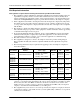
Physical Description NetVanta 6310/6330 Series Hardware Installation Guide Table 1. NetVanta 6310/6330 Series Front Panel LEDs (Continued) LED SLOT 1/SLOT 2 (Analog Modules) SLOT 1/SLOT 2 (BRI S/T Module) SLOT 1/SLOT 2 (ADSL2+ Module) SLOT 1/SLOT 2 (EFM Modules) LAN 1/LAN 2 20 Color Indication Off All ports are inactive or administratively disabled. Green (solid) VIM2 is off-hook. Green (flashing) VIM2 is ringing. Amber (solid) VIM2 module is in test mode.
NetVanta 6310/6330 Series Hardware Installation Guide 3. Features and Specifications FEATURES AND SPECIFICATIONS Interfaces • Supports up to 24 analog ports and one NIM2/VIM2 option slot (NetVanta 6330 Analog Series models) • Supports a single PRA/PRI/E1/T1 interface and two NIM2/VIM2 option slots (NetVanta 6310 PRI model) • Supports a dual auto MDI/MDIX 10/100Base-T Ethernet interface Ethernet Features • 802.
Features and Specifications NetVanta 6310/6330 Series Hardware Installation Guide Voice Features • Supports three-way conferencing • Supports caller ID, message waiting (both frequency shift keying (FSK) and voltage), and stutter dial tone • Fax and analog modem compatible (V.90) • Supports local station-to-station calls Voice Processing • Provides up to 30 channels of G.711 (u-Law) • Provides up to 30 channels of G.
NetVanta 6310/6330 Series Hardware Installation Guide 4. Option Modules OPTION MODULES The NetVanta 6310 Series supports several option modules designed to meet a variety of networking requirements. The option modules include plug-in network and voice interface modules (NIMs/VIMs). NIM2s/VIM2s are cards that plug directly into the option module slot located on the rear of the base unit.
Option Modules NetVanta 6310/6330 Series Hardware Installation Guide Network Interface Modules NetVanta SHDSL, Annex A NIM2 (P/N 1700101G1) The NetVanta SHDSL, Annex A NIM2 (shown in Figure 5) provides a SHDSL 2-wire or 4-wire interface for the NetVanta 6310/NetVanta 6330 Series. See Table A-8 on page 45 for the SHDSL EFM connector pinouts. SHDSL ANNEX A Figure 5.
NetVanta 6310/6330 Series Hardware Installation Guide Option Modules NetVanta SHDSL, Annex B NIM2 (P/N 1700101G2) The NetVanta SHDSL, Annex B NIM2 (shown in Figure 6) provides a SHDSL 2-wire or 4-wire interface for the NetVanta 6310/NetVanta 6330 Series. See Table A-9 on page 45 for the SHDSL connector pinouts. SHDSL ANNEX B Figure 6.
Option Modules NetVanta 6310/6330 Series Hardware Installation Guide NetVanta Quad SHDSL EFM, Annex A NIM2 (P/N 1700103G1) The NetVanta Quad SHDSL EFM, Annex A NIM2 (shown in Figure 7) provides a WAN-SHDSL EFM interface for the NetVanta 6310/NetVanta 6330 Series. See Table A-8 on page 45 and Table A-9 on page 45 for the SHDSL EFM connector pinouts. SHDSL EFM ANNEX A 2 1 3 4 Figure 7.
NetVanta 6310/6330 Series Hardware Installation Guide Option Modules NetVanta Quad SHDSL EFM, Annex B NIM2 (P/N 1700103G2) The NetVanta Quad SHDSL EFM, Annex B NIM2 (shown in Figure 8) provides a WAN-SHDSL EFM interface for the NetVanta 6310/NetVanta 6330 Series. See Table A-8 on page 45 and Table A-9 on page 45 for the SHDSL EFM connector pinouts. SHDSL EFM ANNEX B 1 2 3 4 Figure 8.
Option Modules NetVanta 6310/6330 Series Hardware Installation Guide NetVanta Quad T1/E1 EFM NIM2 (P/N 1700106G1) The NetVanta Quad T1/E1 EFM NIM2 (shown in Figure 9) provides a WAN-T1/E1 EFM interface for the NetVanta 6310/NetVanta 6330 Series. See Table A-10 on page 46 for the T1/E1 connector pinouts. 1 2 3 4 T1/E1 EFM Figure 9.
NetVanta 6310/6330 Series Hardware Installation Guide Option Modules NetVanta Ethernet NIM2 (P/N 1700107G1) The NetVanta Ethernet NIM2 (shown in Figure 10) provides an Ethernet interface for the NetVanta 6310/NetVanta 6330 Series. See Table A-7 on page 45 for the Ethernet module pinouts. ETHERNET 10/100 BASE T Figure 10. NetVanta Ethernet NIM2 Features and Specifications Ethernet Interface Environmental • • • • • Supported Standards: ITU-T I.
Option Modules NetVanta 6310/6330 Series Hardware Installation Guide NetVanta Quad BRI S/T NIM2 (P/N 1700112G1) The NetVanta Quad BRI S/T NIM2 (shown in Figure 11) provides a BRI S/T interface for the NetVanta 6310/NetVanta 6330 Series. See Table A-11 on page 46 for the Quad BRI S/T connector pinouts. 1 2 3 4 ISDN BRI S/T Figure 11.
NetVanta 6310/6330 Series Hardware Installation Guide Option Modules NetVanta ADSL2+ Annex A NIM2 (P/N 1700114G1) The NetVanta ADSL2+ Annex A NIM2 (see Figure 12) adds ADSL capability to the NetVanta 6310/6330 Series. The module provides a single ADSL, ADSL2, or ADSL2+ network interface to support rates up to 25 Mbps. See Figure A-6 on page 45 for the ADSL2+ pinouts. ADSL2+ Annex A Figure 12.
Option Modules NetVanta 6310/6330 Series Hardware Installation Guide Voice Interface Modules NetVanta Quad FXS VIM2 (P/N 1700102G1) The NetVanta Quad FXS VIM2 (see Figure 13) adds voice capability to the NetVanta 6310/NetVanta 6330 Series. See Table A-12 on page 46 for the foreign exchange service (FXS) connector pinouts. 1 2 3 4 FXS Figure 13.
NetVanta 6310/6330 Series Hardware Installation Guide Option Modules NetVanta Quad FXO VIM2 (P/N 1700105G1) The NetVanta Quad FXO VIM2 (see Figure 14) adds voice capability to the NetVanta 6310/NetVanta 6330 Series. See Table A-12 on page 46 for the foreign exchange office (FXO) connector pinouts. 1 2 3 4 FXO Figure 14.
Option Modules NetVanta 6310/6330 Series Hardware Installation Guide NetVanta Octal FXS VIM2 (P/N 1700108G1) The NetVanta Octal FXS VIM2 (see Figure 15) adds voice capability to the NetVanta 6310/NetVanta 6330 Series. See Table A-12 on page 46 for the FXS connector pinouts. 1 2 3 4 5 6 7 8 FXS Figure 15.
NetVanta 6310/6330 Series Hardware Installation Guide Option Modules NetVanta Octal FXO VIM2 (P/N 1700109G1) The NetVanta Octal FXO VIM2 (see Figure 16) adds voice capability to the NetVanta 6310/NetVanta 6330 Series. See Table A-12 on page 46 for the FXO connector pinouts. 1 2 3 4 5 6 7 8 FXO Figure 16.
Option Modules NetVanta 6310/6330 Series Hardware Installation Guide NetVanta Quad FXS/FXO VIM2 (P/N 1700111G1) The NetVanta Quad FXS/FXO VIM2 (see Figure 17) adds voice capability to the NetVanta 6310/NetVanta 6330 Series. See Table A-12 on page 46 for the FXS/FXO connector pinouts. 1 2 3 4 2 1 FXS 3 4 FXO Figure 17.
NetVanta 6310/6330 Series Hardware Installation Guide 5. Unit Installation UNIT INSTALLATION The instructions and guidelines provided in this section cover hardware installation topics, such as mounting options, supplying power to the unit, and installing option cards.
Unit Installation NetVanta 6310/6330 Series Hardware Installation Guide Mounting Options The unit may be installed in rackmount, wallmount, or tabletop configurations. The following sections provide step-by-step instructions for rack mounting and wall mounting. Rack Mounting the NetVanta The NetVanta is a 1U-high, rack-mountable unit that can be installed into a 19-inch equipment rack. The following steps guide you in mounting the NetVanta into a rack.
NetVanta 6310/6330 Series Hardware Installation Guide • Unit Installation To avoid damaging the unit, use only the screws included in the shipment when attaching mounting ears to the chassis. When wall mounting the NetVanta, care must be taken not to damage the power cord. Do not attach the power cord to the building surface or run it through walls, ceilings. floors, or openings in the building structure. The socket-outlet must be installed near the equipment and must be easily accessible.
Unit Installation NetVanta 6310/6330 Series Hardware Installation Guide Supplying Power to the Unit The NetVanta 6310/6330 Series units come equipped with an auto-sensing 100 to 240 VAC, 50/60 Hz power supply for connecting to a properly grounded power receptacle. (A detachable power cable with a grounded, three-prong plug comes with the shipment.) To power this unit, connect the power cable to an appropriate AC power source.
NetVanta 6310/6330 Series Hardware Installation Guide Unit Installation Installing Network and Voice Interface Modules The NIM2s/VIM2s are installed into the rear panel option module slots. The following table lists the installation steps. Also, see Figure 19 below. For NetVanta modules with outside plant connections, ensure that all cables are removed from the module before installing or removing it from the NetVanta chassis. • • • Electronic modules can be damaged by static electrical discharge.
Unit Installation NetVanta 6310/6330 Series Hardware Installation Guide Installing a CompactFlash Card The CompactFlash slot supports only the ADTRAN-provided 1 GB CompactFlash card. Follow these instructions when installing a card. The CompactFlash card is hot-swappable, and can be inserted or removed while power is applied to the unit. Instructions for Installing a CompactFlash Card Step Action 1 Slide the module into the CompactFlash slot until the card is firmly seated against the chassis.
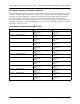
APPENDIX A. CONNECTOR PIN DEFINITIONS The following tables provide the pin assignments for the base unit and network interface modules (NIMs). Base Unit Pinouts Table A-1. CONSOLE Port Pinouts Pin Name Description 1 DCD 2 RD Receive Data (output) 3 TD Transmit Data (input) 4 DTR 5 SG 6 DSR Data Set Ready (output) 7 RTS Request to Send (input) 8 CTS Clear to Send (output) 9 — Data Carrier Detect (output) Data Terminal Ready (input) Signal Ground Unused Table A-2.
Appendix A NetVanta 6310/6330 Series Hardware Installation Guide Table A-4. FXO Connector Pinouts Pin Name Description 1, 2 — 3 Ring 4 Tip Tip lead of the 2-wire interface 5, 6 — Unused Unused Ring lead of the 2-wire interface Table A-5.
NetVanta 6310/6330 Series Hardware Installation Guide Appendix A Network Interface Module Pinouts Table A-6. ADSL2+ Pinouts Pin Name Description 1, 2 — Unused 3 R Network–Ring 4 T Network–Tip 5, 6 — Unused Table A-7. Ethernet Module Pinouts Pin Name Description 1 TR+ Transmit Positive 2 TR- Transmit Negative 3 RX+ Receive Positive 4, 5 — 6 RX- 7, 8 — Unused Receive Negative Unused Table A-8.
Appendix A NetVanta 6310/6330 Series Hardware Installation Guide Table A-10. T1/E1 EFM (Ports 1 through 4) Pinouts Pin Name Description 1 RX Ring Receive 2 RX Tip Receive 3 — Unused 4 TX Ring Transmit 5 TX Tip Transmit Table A-11. BRI S/T Module Pinouts Pin Name Description 1, 2 — Unused 3 Receive Receive 4, 5 Transmit Transmit 6 Receive Receive 7, 8 — Unused Voice Interface Module Pinouts Table A-12.