TSU T1-FT1 Data/Channel Service Unit Part Number 1200060L1 User Manual 61200060L1-1B September 1999
901 Explorer Boulevard P.O. Box 140000 Huntsville, AL 35814-4000 (256) 963-8000 © 1999 ADTRAN, Inc. All Rights Reserved. Printed in U.S.A.
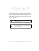
Notes provide additional useful information. Cautions signify information that could prevent service interruption. Warnings provide information that could prevent damage to the equipment or endangerment to human life.
FCC regulations require that the following information be provided to the customer in this manual. 1. This equipment complies with Part 68 of the FCC rules. The required label is affixed to the bottom of the chassis. 2. If your telephone equipment causes harm to the telephone network, the Telephone Company may discontinue your service temporarily. If possible, they will notify you in advance. But if advance notice isn’t practical, you will be notified as soon as possible.
Federal Communications Commission Radio Frequency Interference Statement This equipment has been tested and found to comply with the limits for a Class A digital device, pursuant to Part 15 of the FCC Rules. These limits are designed to provide reasonable protection against harmful interference when the equipment is operated in a commercial environment.
Important Safety Instructions When using your telephone equipment, please follow these basic safety precautions to reduce the risk of fire, electrical shock, or personal injury: 1. Do not use this product near water, such as near a bath tub, wash bowl, kitchen sink, laundry tub, in a wet basement, or near a swimming pool. 2. Avoid using a telephone (other than a cordless-type) during an electrical storm. There is a remote risk of shock from lightning. 3.
WARRANTY AND CUSTOMER SERVICE ADTRAN will replace or repair this product within five years from the date of shipment if the product does not meet its published specifications or if it fails while in service. For detailed warranty, repair, and return information see the ADTRAN Equipment Warranty and Repair and Return Policy Procedure on the inside back page of this manual. Return Material Authorization (RMA) is required prior to returning equipment to ADTRAN.
viii
Table of Contents Chapter 1. Introduction .......................................................................................... 1-1 T1/FT1 Overview ..................................................................................................... 1-1 T1 Service Offerings........................................................................................... 1-1 Fractional T1........................................................................................................ 1-2 TSU Overview ..
Table of Contents Unpack, Inspect, Power Connection ...................................................................... 2-1 ADTRAN Shipments Include ........................................................................... 2-1 Customer Provides............................................................................................. 2-1 Power Connection .............................................................................................. 2-1 Wiring .........................................
Table of Contents PORT TESTS ........................................................................................ 3-8 Menu Operation ....................................................................................................... 3-9 Status Menu ........................................................................................................ 3-9 NI PERF RPTS, Submenu of 1)Status .................................................... 3-10 CURR ERR/ALM Submenu of 1)Status ....................
Table of Contents xii TSU User Manual 61200060L1-1
List of Figures Figure 1-1. Figure 1-2. Figure 1-3. Figure 1-4. Figure 1-5. Figure 1-6. Figure 1-7. Figure 1-8. Figure 1-9. Figure 3-1. Figure 3-2. Figure 3-3. Figure 3-4. Figure 3-5. Figure 3-6. Figure A-1. Figure B-1. 61200060L1-1 TSU .......................................................................................................1-3 TSU Rear Panel ..................................................................................1-4 TSU Interfaces ..................................................
List of Figures xiv TSU User Manual 61200060L1-1
List of Tables Table 2-1. Table 2-2. Table 2-3. Table 2-4. Table 3-1. 61200060L1-1 Network Pin Connection ...................................................................2-2 Control In/Chain In Pin Connection ...............................................2-3 Chain Out Pin Connection ................................................................2-4 Primary V.35 Pin Connection ...........................................................2-5 Normal Mode of Operation ......................................
List of Tables xvi TSU User Manual 61200060L1-1
Chapter 1 Introduction T1/FT1 OVERVIEW T1 digital communication links have been used by the transmitting companies (Telcos) for the transmitting of voice since the early sixties. The D4 channel bank is an example of a T1 digital carrier system that was introduced in the mid seventies and is still widely used by the Telcos. Communication demands of businesses continued to grow to the point that the Telcos began offering T1 service directly to the public.
Chapter 1. Introduction performance of their service offering. Since the introduction of ESF, equipment that is installed in private networks can also provide the same performance information to the user. Fractional T1 Fractional T1 lets the buyer purchase less than a full T1 circuit between two points. Most carriers offer fractional T1 in increments of 56 or 64 kbps. Connection is made to the same network elements. The network allows multiple users to share the same interoffice T1 bandwidth.
Chapter 1. Introduction TSU OVERVIEW TSU ENTER SCROLL CANCEL Figure 1-1. TSU Functional Description The ADTRAN TSU is one of several T1 multiplexers that offers complete flexibility for connection of various data sources to T1 or FT1 facilities. This family of TSU multiplexers includes the following. 1. TSU - a T1 CSU/DSU with a single NX56k/64k serial port. See Figure 1-1, above and Figure 1-2 on page 1- 4. 2.
Chapter 1. Introduction 1 2 3 4 5 6 7 8 9 ON TEST JACKS CONTROL OFF NETWORK IN OUT MON CHAIN IN CHAIN OUT Item 1. Network 115VAC/60HZ .15A V.35 NX56/64 Function T1-FT1 Network Interface Test Jacks 2. IN Bantam Test Jack 3. OUT Bantam Test Jack 4. MON (Monitor) Bantam Test Jack Control 5. Chain In Interface of Chain In 6.Chain Out Connects to Chain In of another TSU 7. V.35 Nx56/64 DTE Port 8. Power Switch Used to turn power On or OFF 9.
Chapter 1. Introduction Features • A DS1 interface and an Nx56/64 DTE serial interface port. • Easy configuration capabilities using simplistic menus displayed in a Liquid Crystal Display (LCD) window operated by a front panel keypad. • Timing is selectable from the network, from the Nx56/64 DTE port, or internally. • All ones, 3:24, 511 and 1:8 Test Patterns. • Extensive self test and monitoring provides assurance of proper operation.
Chapter 1. Introduction Network Interface The Network Interface (NI) port complies with the applicable ANSI and AT&T standards. NI • AMI or B8ZS coding • Automatic or manual line build out • D4 or ESF framing • Network performance monitoring and reporting • Test loopbacks by local and remote • Extensive self test Nx56/64 Serial Interface • Data rates: N*56k or N*64k, where N=1 to 24 (DS0s) • Inverted data (Inverted HDLC) • A V.35 interface • Standard V.
Chapter 1. Introduction Three Methods of Control Front Panel The front panel provides complete and easy control of all items that can be configured through menu guided options. The front panel LCD also displays the status of operation and performance reports for the unit. A complete discussion of the operation of the front panel and all the menu options is found in Chapter 3, Operation. Adtran PC Program T-WATCH is the ADTRAN PC control program.
Chapter 1. Introduction TSU Clock Sources The TSU is operable from various clock sources permitting it to perform properly in many different applications. The network interface clocking options are set by using the Network (NI) Configuration menu options. There are three clock source options available. • Network • DTE Timed • Internal Timing The clocking option selected always designates the clock source for transmission.
Chapter 1. Introduction DTE Timed The DTE is the source of timing. The TSU uses the incoming DTE clock to determine the transmission timing. This is typically used in applications where it is necessary to have the DTE as the Primary Clock Source, (such as limited distance line drivers). See Figure 1-5. OSC T1 XMIT (DSU) T1 Receive Network Interface NX56K/64K DTE CLOCK DTE Figure 1-5.
Chapter 1. Introduction Internal Timing The TSU is the source of timing. The TSU is configured to use its own internal oscillator as the source of timing. Applications include private line driver circuits where one end is set to network and the other to internal. See Figure 1-6. OSC T1 XMIT (DSU) T1 Receive Network Interface NX56K/64K DTE CLOCK DTE Figure 1-6.
Chapter 1. Introduction TSU Testing Currently the TSU offers three forms of testing. • Self Test • Loopback Tests • Pattern generation and check Self Tests The self test checks the integrity of the internal operation of the electronic components by performing memory tests and by sending and verifying data test patterns through all internal interfaces.
Chapter 1. Introduction Network Loopbacks There are two types of network loopbacks; see Figure 1-7. • Line Loopback: loops all of the received data back toward the network. The transmitted data is the identical line code that was received, including any bipolar violations or framing errors. • Payload Loopback: similar to Line loopback, except that the framing is extracted from the received data and then regenerated for the transmitted data. TSU V.
Chapter 1. Introduction DTE Interface Loopbacks The Nx56k/64k serial interface offers a DTE loopback. See Figure 1-8. DTE Loopback: loops all data from the DTE back towards the DTE. This loopback may be initiated by the DTE asserting the Local Loopback (LL) input on the connector or by using front panel or T-WATCH commands. The DTE (or external test equipment) must provide any test pattern in order to check the DTE interface.
Chapter 1. Introduction 511 The 511 pattern is generated and checked by the Nx56k/64k serial interface. It only appears in the DS0s assigned to the Nx56k/64k port. When used in conjunction with the payload loopback at the far end as previously described, an end to end integrity check can be made on the DTE ports. 1 in 8 The 1:8 pattern is used similarly to the 3:24. Each channel of the T1 has only one bit set. Application Using the V.35 DTE interface, a bridge or router can be interfaced to the network.
Installation Chapter 2 UNPACK, INSPECT, POWER CONNECTION Carefully inspect the TSU for any shipping damages. If damage is suspected, file a claim immediately with the carrier and then contact ADTRAN Customer and Product Service. If possible, keep the original shipping container for use in shipping the TSU back for repair or for verification of damage during shipment.
Chapter 2. Installation Power to the TSU must be from a 115 VAC, 60Hz that is grounded. WIRING Network On the rear panel the TSU has an eight-position modular jack labeled NETWORK. This connector is used for connecting to the network. See Table 2-1 for the pinout for the Network connector. Connector Type - (USOC) RJ48C pn - AMP# 555164-2 Table 2-1.
Chapter 2. Installation Control In/Chain In Used as an EIA 232 port for connection to a computer or modem (Chain In); or another TSU (Chain Out). See Table 2-2. Connector Type - RJ48 pn - AMP# 555164-2 Table 2-2.
Chapter 2. Installation Chain Out Used to connect to another TSU's Chain In connector. See Table 2-3. Connector Type - RJ48 pn - AMP# 555164-2 Table 2-3. Chain Out Pin Connection CHAIN OUT PIN CONNECTION PIN 2-4 NAME 1 GND 2 UNUSED 3 TXDATA 4 UNUSED 5 RXDATA 6, 7, 8 UNUSED DESCRIPTION Ground-Connected to Unit Chassis Connect to GND of next unit (Pin 1). Data Transmitted to chained units by the TSU. Connect to RX DATA of the next unit (Chain In Pin 3).
Chapter 2. Installation Nx56k/64k DTE (V.35) Connector Type = V.35 pn = AMP# 92-4883-3-1 See Table 2-4. Table 2-4. Primary V.
Chapter 2. Installation POWER UP TESTING AND INITIALIZATION When shipped from the factory, the TSU is uninitialized and set to factory default conditions. At the first application of power, the unit will automatically execute self tests followed by an initialization sequence which sets up the unit. Self Test Upon a power-up or commanded self tests the LCD displays ADTRAN TSU INITIALIZING and the LEDs illuminate sequentially.
Operation Chapter 3 METHODS OF OPERATION The TSU can be configured and controlled by two different methods: 61200060L1-1 • Local Front Panel • From Adtran’s PC Control program, T-WATCH TSU User Manual 3-1
Chapter 3. Operation Front Panel Operation 1 2 3 4 10 12 TSU PWR ERR ALM LB TD RD RS CS 5 6 7 8 Item ENTER SCROLL CANCEL 9 11 13 Function Displays: 1 PWR: LED "ON" when power is received by TSU. 2 ERR: LED "ON" when errored events have happened in the last second. 3 ALM LED "ON" when an alarm condition exists. 4 LB LED "ON" when unit is in loopback. 5 TD LED "ON" when DTE data is being transmitted. 6 RD LED "ON" when DTE data is being received.
Chapter 3. Operation General Menu Operation The TSU uses a multilevel menu structure containing both menu items and data fields. All menu operations and data are displayed in the LCD window. The menu items are numbered and can be viewed by using the up and down scroll keys. Data Field A menu item followed by a colon (:) identifies an editable data field. Display Field A menu field followed by alarm or error information.
Chapter 3. Operation 2. With the cursor on the number 2, press the ENTER key. The unit responds by displaying the first two available submenu fields. The cursor is on the first field. If there are more than two menu fields, a down scroll key is visible on the lower right corner. 1)NETWORK (NI) 2)UNIT 3. To select the desired submenu item, use the up and down scroll keys to place the cursor on the desired menu item, for example, 1) NETWORK (NI).
Chapter 3. Operation 3. When the desired value is in the data field position, press ENTER to set the value. The unit is set for the value shown in the data field and the cursor moves back to the submenu item position indicating the operation is complete. 4. Select another submenu field or use the CANCEL key to return to the submenu. CANCEL is available any time during the operation.
Chapter 3. Operation Menu Structure The TSU uses hierarchical menus to access its many features. The main menu leads to submenus which are grouped by function. All menu operations are displayed in the LCD window. 1)STATUS 2)CONFIG 3)UTIL 4)TEST This menu structure diagram is a limited overview. A detailed description of each menu item, presented in menu order is shown in Figure 3-2. A complete menu is shown in Appendix A.
Chapter 3. Operation The opening menu is the access point to all other operations. There are four main menu items, 1)STATUS, 2)CONFIGURE, 3)UTILITY, 4)TEST. Each main menu item has several functions and submenus to identify and access specific parameters. In the discussions that follow, each main menu contains a complete menu diagram to identify the location of each operation. The Four Opening Menu Functions STATUS The Status menu provides the ability to view the status of the TSU operation.
Chapter 3. Operation UTIL The Utility menu is used to view and to set system parameters. This menu includes the following subitems. TIME/DATE Accesses the display and allows the setting of the current time and date. SOFTWARE VERSION Displays the version number of the current software revision level. This information is required when requesting assistance from ADTRAN Customer and Product Service or when updates are needed. REINIT UNIT Used to reinitialize the unit.
Chapter 3. Operation MENU OPERATION Status Menu The Status menu branch provides the ability to view the status of the TSU operation. See Figure 3-3. RESET PERF CNTRS 1) NI PERF RPTS SES LOSS OF SIGNAL ES AIS ALARM % AV OUT OF FRAME % EF YELLOW ALARM Calves RED ALARM 2) CURR ERR/ALM CODE VIOLATIONS 1) STATUS BIPOLAR VIOLATIONS CLEAR HISTORY FRAME BIT ERRORS LOSS OF SIGNAL.
Chapter 3. Operation NI PERF RPTS, Submenu of 1)Status The Network Interface Performance Reports displays the user copy of the performance data. The TSU maintains this performance data on the network in compliance with ANSI T1.403 and AT&T document TR54016. The data displayed is data accumulated over the last 15 minutes and over the last 24 hours. 1. With the cursor on main menu item, 1)STATUS, press ENTER. The first two Status submenu items with the cursor on 1)NI PERF RPTS displays. 2. Press ENTER.
Chapter 3. Operation These fields cannot be edited, only cleared as previously discussed. Only the user copy of performance data is cleared. 15 Minutes 24 Hours 1)SES 15MI N / 24HR 10 / 120 Data Values Number of Severely Errored Seconds SES - ES - Number of Errored seconds %AV - % of Available seconds %EF - % of Error free seconds CVs - Number of Code Violations Continue with standard operating procedures to exit the display.
Chapter 3. Operation CURR ERR/ALM Submenu of 1)Status The Current Error/Alarm menu is used for viewing currently Active/Inactive errors and alarms. 1. With the cursor on main menu item 1)STATUS, press ENTER. The first of three Status submenu items with the cursor on 1)NI PERF RPTS displays. 2. Press the down scroll key. 3. Press ENTER. The results display the first current ERRORS/ALARMS screen.
Chapter 3. Operation ERR/ALM Hist Submenu of 1)Status The Error/Alarm History menu is used for viewing history of errors and alarms. If an alarm has occurred since the last CLEAR HISTORY selection, the menu will be ACTIVE. If the condition hasn't occured then the menu will be INACTIVE. 1. With the cursor on main menu item 1)STATUS. 2. Press ENTER. The first of three status submenu items display. 3. Press the down scroll key twice. The cursor is on 3)ERR/ALM HIST. 4. Press ENTER.
Chapter 3. Operation Configuration The Configuration menu is used to set the TSU operational configuration, including all of the network interface parameters, the allocation of the DS0s and the port parameters. See Figure 3-4.
Chapter 3. Operation 1) NETWORK (NI) SUBMENU OF 2) CONFIG This menu is used to access the configuration of parameters associated with the network interface in the TSU. There are seven submenu items that include setting the format, the Line Build Out (LBO), the clock source, etc. Follow the standard operating procedure to access the Network (NI) menu item. 1. With the cursor on 1)NETWORK (NI), press ENTER. The results display the first of two submenu items.
Chapter 3. Operation XMIT PRM Enables and disables the transmitting of Performance Report Messages (PRM) data on the Facility Data Link (FDL). The PRM data continues to be collected even if XMIT PRM is disabled. (Possible only with ESF Format.) Choices: ENA, DISA CLOCK SOURCE Selects the clock source for transmission toward the network form the NI.
Chapter 3. Operation 2) UNIT, SUBMENU OF 2) CONFIG The unit submenu is used to change control port and alarm options. 1. Follow standard operating procedures to access the Unit menu item. 2. With the cursor on 2)UNIT, press ENTER. The results display two submenu items. 1)CONTROL PORT 2)ALARMS 1) CNTRL PORT Used to set the unit up as the Master or Slave on a chain of units, and whether to initialize a modem and the control port data rate.
Chapter 3. Operation DATA RATE Selects the data rate for the control port. This should be consistent with all units on a chain and with the modem and/or PC/Proxy Agent serial port. Choices: 1200, 2400, 9600 2) ALARMS Used to initialize the method by which the control port handles alarm conditions. TRAPS This setting determines if alarm conditions should automatically send alarm messages (traps) to the controlling PC/Proxy Agent. The setting is for this unit, or for slaves if this unit is a master.
Chapter 3. Operation 3) PORT, SUBMENU OF CONFIG The menu item PORT is used to select and then to configure the parameters associated with the V.35. 1. Follow standard operating procedure to access 3)PORT. 2. Press ENTER. The first nine submenu items appear. 3. Continue with standard operating procedures. RATE 56/64 This sets the base rate of the interface. The actual data rate depends on the number of DS0s assigned to the Nx port. The DTE data rate vs. the number of DS0s appear in Appendix II.
Chapter 3. Operation # OF CHAN Used to select the number of DS0s (channels) that are to be used. The corresponding DTE rate will be this number times 56K or 64K, depending on Port Option number 1. Choices: 01 through 24 DATA Used to control the inverting of the DTE data. This inversion can be useful when operating with an HDLC protocol. Often used as a means to ensure ones (1s) density. TSUs on both ends must have identical option settings.
Chapter 3. Operation UTIL The utility menu is used to view and to set system parameters. See Figure 3-5. This includes setting the time and date and resetting all parameters to factory values or to reinitialize the unit. This menu is also used to view the unit’s software revision and the unit's ID setting.
Chapter 3. Operation 1. With the cursor on 1)TIME/DATE press ENTER. The results display the current time and date with the cursor on the T in Time. TIME:05:07:06 DATE:08/05/93 2. Press ENTER to move to the first time position (hour). Use one or two number keys to set the desired hour. 3. Press ENTER. The cursor moves to the second time position (minutes). 4. Use one or two number keys to set the desired minutes. Press ENTER. The cursor moves to the third time position (seconds). 5.
Chapter 3. Operation The up and down scroll keys will also move the cursor to different fields to edit. Pressing CANCEL at any time can be used to end the editing process. 2)Software Rev, Submenu of 3)Util Use the Software Revision submenu to access the display of the current software revision level. This information is required when requesting assistance from ADTRAN Customer Service or when updates are needed. Follow standard operating procedure to access the 3)UTIL menu items. 1.
Chapter 3. Operation 4)Address,Submenu of 3)Util This submenu is used to access the current Unit Address setting. Unit identification numbers must be between 000 and 256. 1. Follow standard operating procedure to access the 3)UTIL menu items. 2. With the cursor on 4)ADDRESS, press ENTER. The results display the prompt to enter the Unit Identification number limited to three digits between 000 and 256. 3)REINIT 4)ADDRESS: 000 3. Press ENTER to active the menu.
Chapter 3. Operation Test The Test menu is used to initiate different types of tests of the unit and to view test results. Test results are displayed in the LCD window. The menu contains three subitems. See Figure 3-6. Executing tests will disrupt some of the normal operation. See individual menu items concerning tests before executing. LINE ON 1 LOCAL LOOPBK NO LOOPBACK PAYLOAD ON 2 REMOTE LOOPBK NO LOOPBACK V.
Chapter 3. Operation 1)Network Tests, Submenu of 4)Test Network Tests are used to control the activation of loopbacks and the initiation of data test patterns. The Network tests are run on the Network INterface (NI). Three different test configurations can be selected to determine the type of loopback and the pattern to run. Test results are displayed in the LCD window. 1. With the cursor on main menu item 4)TEST, press ENTER. The first twoTest submenu items with the cursor on 1)NETWORK TESTS displays.
Chapter 3. Operation • V.54 Inband PLB - indicates inband transmission of V.54 loopup pattern in channels occupied by DTE data only. This choice should be used for public fractional network • ANSI FDL LLB - initiates the transmission of an FDL Line loopup code toward the far end.
Chapter 3. Operation 4)CLR 511 ERRORS - Accomplishes two functions. First, it clears out the 511 error total when ENTER is pressed. Second, it displays a total of the 511 errors. If 511 errors are being received, the display is updated accordingly. CLR 511 ERRORS 511 ERRORS = 56 This menu function is very useful for testing end-to-end integrity of the network. First loopup the far end TSU. Then send a 511 pattern from the local TSU.
Chapter 3. Operation 1. Follow standard operating procedure to access the 4)TEST menu item. 2. With the cursor on 2)RUN SELFTEST, press ENTER. A changing display in the LCD showing the test outcome displays. SYSTEM SELF-TEST ALL TESTS PASSED 3. Press the CANCEL key to exit. 3)Port Tests submenu of 4)Test Port Tests are used to control the activation of a DTE loopback. This test loops data received at theV.35 interface back towards the DTE. 1. With the cursor on main menu item 4)TEST, press ENTER.
Chapter 3.
Testing Example Chapter 4 Prior to actually using the TSU to pass data, it is recommended to run tests on the circuit. The testing consists of sending a test pattern from end to end and checking for errors in the pattern. There are two types of tests used to accomplish this. • Send the pattern from one end and loopback the far end. • Send the pattern from both ends and check at both ends. Far End Looped Back Test Two types of tests can be executed with the far end looped.
Chapter 4. Testing Example 1)NETWORK TESTS 2)RUN SELF TEST 3. Use the scroll keys to place the cursor on 1)NETWORK TESTS. 4. Press ENTER to select. 5. Press ENTER again to enter the NETWORK TEST MENU. The beginning display of the submenu items display. The selections available for each menu item are selected with the up and down scrolls. 1)LOCAL LOOPBK: NO LOOPBACK 2)REMOTE LOOPBK: NO LOOPBACK 3)TEST PATTERN: NONE LINE ON PAYLOAD ON NO LOOPBACK V.
Chapter 4. Testing Example 8. Use the up and down scroll keys to set PAYLOAD in data the field. (Must use V.54 PLB ON For Fractional T1 on Public Networks.) 9. Press ENTER to activate a Remote Payload Loopback . This initiates the transmission of a loopup code toward the far end. 10. When completed use the up and down scroll key or the number 3 to select 3)TEST PATTERN. 11. Press ENTER to activate the TEST PATTERN submenu. 12. Use the up and down scroll keys to select 511 ALL DS0s. 13.
Chapter 4.
TSU Complete Menu Appendix A RESET PERF CNTRS 1) NI PERF RPTS SES ES % AV LOSS OF SIGNAL %EF AIS ALARM CVS OUT OF FRAME 2) CURR ERR/ALM 1) STATUS YELLOW ALARM CLEAR HISTORY RED ALARM LOSS OF SIGNAL CODE VIOLATIONS AIS ALARM BIPOLAR VIOL OUT OF FRAME FRAME BIT ERRORS YELLOW ALARM PLL ALARM RED ALARM CODE VIOLATIONS 3) ERR/ALM HIST BIPOLAR VIOLATIONS FRAME BIT ERRORS PLL ALARM 1) FORMAT 2) CODE 3) YEL ALRM 1) NETWORK (NI) 4) XMIT PRM 1) POSITION 1) CNTRL PORT 2)MODEM INIT 3)DATA RA
Appendix A.
Appendix B DTE Data Rate Chart DTE DATA RATE vs DS0s (N) # of DS0s (N) DTE RATE = 56K DTE RATE = 64 N=1 56K 64K N=2 112K 128K N=3 168K 192K N=4 224K 256K N=5 280K 320K N=6 336K 384K N=7 392K 448K N=8 448K 512K N=9 504K 576K N = 10 560K 640K N = 11 616K 704K N = 12 672K 768K N = 13 728K 832K N = 14 784K 896K N = 15 840K 960K N = 16 896K 1024K N = 17 952K 1088K N = 18 1008K 1152K N = 19 1064K 1216K N = 20 1120K 1280K N = 21 1176K 1344K N = 22 1232K 1408K N = 23 1288K 1472K N = 24 1344K 1536K Figure B-1.
Appendix B.
Index Symbols E (NI) Network Interface 1-6 exit menu operation 3-5 Extended Superframe 1-1 Numerics 1 in 8, test pattern 1-14 3 in 24, test pattern 1-13 511, test pattern 1-14 A All Ones, test pattern 1-13 Application 1-14 Arrows, Menus 3-3 C Chain Out 2-4 Chain Port Output 1-6 Configuration Menu Overview 3-7 Control In/Chain In 2-3 Control Port Input 1-6 Customer Service vii Customer Service, Warranty vii F factory default 3-24 Far End Loop Back Test 4-1 Federal Communications Commission Radio Frequ
Index Network Interface Test 4-1 Network Loopbacks 1-12 Network Timed 1-8 Network, rear panel modular jack 2-2 Nx56/64 Serial Interface 1-6 Nx56k/64k DTE (V.
Product Support Information Presales Inquiries and Applications Support Please contact your local distributor, ADTRAN Applications Engineering, or ADTRAN Sales: Applications Engineering (800) 615-1176 Sales (800) 827-0807 Post-Sale Support Please contact your local distributor first. If your local distributor cannot help, please contact ADTRAN Technical Support and have the unit serial number available.