TA 544 User Manual/61200704L1-1A Page 1 of 68 TA 544 User Manual 1200704L1 4200704L3 TA 544 TA 544 with SDSL Card 61200704L1-1A May 2001 © 2001, ADTRAN, Inc.
TA 544 User Manual/61200704L1-1A Page 2 of 68 Trademarks Any brand names and product names included in this manual are trademarks, registered trademarks, or trade names of their respective holders. Total Access is a registered trademark of ADTRAN, Inc. To the Holder of the Manual The contents of this manual are current as of the date of publication. ADTRAN reserves the right to change the contents without prior notice.
TA 544 User Manual/61200704L1-1A Page 3 of 68 Notes provide additional useful information. Caution signify information that could prevent service interruption. Warnings provide information that could prevent damage to the equipment or endangerment to human life. Safety Instructions When using your telephone equipment, please follow these basic safety precautions to reduce the risk of fire, electrical shock, or personal injury: 1. Read and understand all instructions. 2.
TA 544 User Manual/61200704L1-1A Page 4 of 68 Limited Product Warranty ADTRAN warrants that for 5 years from the date of shipment to Customer, all products manufactured by ADTRAN will be free from defects in materials and workmanship. ADTRAN also warrants that products will conform to the applicable specifications and drawings for such products, as contained in the Product Manual or in ADTRAN's internal specifications and drawings for such products (which may or may not be reflected in the Product Manual).
TA 544 User Manual/61200704L1-1A Page 5 of 68 International Contact Information ADTRAN, Inc. Attention: International Department 901 Explorer Boulevard Huntsville, Alabama 35806 USA www.adtran.com Asia Pacific—Beijing, China 8610 8529-8895 voice 8610 8529-8866 fax sales.china@adtran.com Asia Pacific—Hong Kong 852 2824-8283 voice 852 2824-8928 fax sales.asia@adtran.com Asia Pacific—Melbourne, Australia 61 3 9225-5114 voice 61 3 9225-5050 fax sales.asia@adtran.
TA 544 User Manual/61200704L1-1A Page 6 of 68 Northern Europe/Russia--London, United Kingdom 44 1252 626-730 voice 44 1252 617-850 fax sales.northeurope@adtran.com U.S. Headquarters 1 256 963-8000 voice 1 256 963-6300 fax 1 256 963-8200 fax back international@adtran.com TA 544 User Manual © 2001, ADTRAN, Inc.
TA 544 User Manual/61200704L1-1A Page 7 of 68 Customer Service, Product Support Information, and Training ADTRAN will replace or repair this product within 5 years from the date of shipment if the product does not meet its published specification, or if it fails while in service. A return material authorization (RMA) is required prior to returning equipment to ADTRAN. For service, RMA requests, training, or more information, see the tollfree contact numbers given below.
TA 544 User Manual/61200704L1-1A Page 8 of 68 or possible fees associated with repair, contact CAPS directly at the following number: CAPS Department (256) 963-8722 Identify the RMA number clearly on the package (below address), and return to the following address: ADTRAN Customer and Product Service 901 Explorer Blvd. Huntsville, Alabama 35806 RMA # _____________ Training The Enterprise Network (EN) Technical Training offers training on our most popular products.
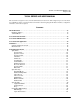
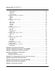
TA 544 User Manual/61200704L1-1A Page 9 of 68 TA 544 SERIES IAD USER MANUAL This document is designed for use by network administrators and others who will configure and provision the Total Access® 544. It contains overview information, information about navigating the VT 100 user interface, configuration information, and menu descriptions. CONTENTS TA 544 Overview . . . . . . . . . . . . . . . . . . . . . . . . . . . . . . . . . . . . . . . . . . . . . . . . . . . . . . . . . . . . . . . .
TA 544 User Manual/61200704L1-1A Page 10 of 68 Layer Two Protocol . . . . . . . . . . . . . . . . . . . . . . . . . . . . . . . . . . . . . . . . . . . . . . . . . . . . . . . . 25 ATM Config . . . . . . . . . . . . . . . . . . . . . . . . . . . . . . . . . . . . . . . . . . . . . . . . . . . . . . . . . . . . . . 25 ATM Stats . . . . . . . . . . . . . . . . . . . . . . . . . . . . . . . . . . . . . . . . . . . . . . . . . . . . . . . . . . . . . . . 26 DSL Rate Config . . . . . . . . . . . . . . . . . . .
TA 544 User Manual/61200704L1-1A Page 11 of 68 FIGURES Figure 1. Figure 2. Figure 3. Figure 4. Figure 5. Figure 6. Figure 7. Figure 8. Figure 9. Figure 10. Figure 11. Figure 12. Figure 13. Figure 14. Figure 15. Figure 16. Figure 17. Figure 18. Figure 19. Figure 20. Figure 21. TA 544 Rear Panel. . . . . . . . . . . . . . . . . . . . . . . . . . . . . . . . . . . . . . . . . . . . . . . . . . . . . Voice over DSL . . . . . . . . . . . . . . . . . . . . . . . . . . . . . . . . . . . . . . . . . . . . . . . .
TA 544 User Manual/61200704L1-1A Page 12 of 68 TA 544 User Manual © 2001, ADTRAN, Inc.
TA 544 User Manual/61200704L1-1A Page 13 of 68 1. TA 544 OVERVIEW The Total Access 544 is a complete solution Integrated Access Device (IAD) for Voice over ATM (VoATM) applications. The unit includes a modular network interface, Nx64 V.35 interface, 10/100BaseT interface, ISDN ports, and an optional battery back-up (1200641L1) for added security. The TA 544 can provision, test, and provide status for any of the voice and data interfaces. All connections are made via the rear panel (see Figure 1).
TA 544 User Manual/61200704L1-1A Page 14 of 68 small, fixed-length cells require lower processing overhead. Second, these small, fixed-length cells allow higher transmission speeds than traditional packet switching methods. ATM allocates bandwidth on demand, making it suitable for high-speed connection of voice, data, and video services. Conventional networks carry data in a synchronous manner. Because empty slots are circulating even when the link is not needed, network capacity is wasted.
TA 544 User Manual/61200704L1-1A Page 15 of 68 5. INSTALLATION Unpack and Inspect the Unit After unpacking the unit, inspect it for possible shipping damage. If the equipment has been damaged in transit, immediately file a claim with the carrier, then contact ADTRAN Customer Service. Shipped by ADTRAN The following items are included in the ADTRAN shipment: • The TA 544 • DB-9 adapter • 6 ft.
TA 544 User Manual/61200704L1-1A Page 16 of 68 6. CONFIGURING THE TA 544 System Info The SYSTEM INFO menu provides basic information about the unit and contains data fields for editing information. Figure 3 displays the submenus available when you select this menu item. Figure 3. System Information Menu > System Name Provides a user-configurable text string for the name of the TA 544. This name can help you distinguish between different installations.
TA 544 User Manual/61200704L1-1A Page 17 of 68 > Part Number ADTRAN part number for the product assembly. > Serial Number Serial number of the product assembly. > Firmware Revision Displays the current firmware revision level of the controller. > Bootcode Revision Displays the bootcode revision. > System Uptime Displays the length of time since the TA 544 system reboot. > Date/Time Displays the current date and time, including seconds. This field can be edited.
TA 544 User Manual/61200704L1-1A Page 18 of 68 System Config Set up the TA 544 operational configuration from the SYSTEM CONFIG menu. Figure 4 shows the items included in this menu. Figure 4. System Configuration Menu > Operating Mode The operating mode is set automatically. > Network Timing Mode Selects the timing source for the entire system. The timing options available are listed below. Network The clock is recovered from the network (WAN interface).
TA 544 User Manual/61200704L1-1A Page 19 of 68 Password When the authenticating method is password, this text string is used for the password. Idle Time (1-255) This sets the amount of time you can be idle before you are automatically logged off. Level This is the security level granted to the user. > SNMP Menu The TA 544 is an SNMP agent. It can respond to Gets and Sets, and can generate traps. These two lists set up the manager, communities, and levels. Access When set to OFF, SNMP access is denied.
TA 544 User Manual/61200704L1-1A Page 20 of 68 > Maint Port Menu The TA 544’s VT 100 CRAFT port can be accessed via an RJ-48 located on the rear panel. The setup for these ports is under this menu. Password Protect When set to OFF, the maintenance port is not password protected. When ON (def), the TA 544 will prompt for a password upon startup. Password This is the text string that is used for comparison when password protecting the maintenance port. By default, no password is entered.
TA 544 User Manual/61200704L1-1A Page 21 of 68 Baud Rate This is the asynchronous rate that the maintenance port will run. The possible values are 300, 1200, 2400, 4800, 9600 (def), 19200, 38400, and 57600. Data Bits This is the asynchronous bit rate that the maintenance port will run. The possible values are 7 or 8 (def) bits. Parity This is the asynchronous parity that the maintenance port will run. The possible values are NONE (def), ODD, or EVEN.
TA 544 User Manual/61200704L1-1A Page 22 of 68 Status This displays the current status of the time negotiation process. If an error is displayed, check all connections and configurations to try to resolve the problem. System Utility Use the SYSTEM UTILITY menu to view and set the system parameters shown in Figure 5. Figure 5. System Utility Menu > Upgrade Firmware Updates firmware when TA 544 enhancements are released. Two transfer methods are available for use in updating the TA 544 system controller.
TA 544 User Manual/61200704L1-1A Page 23 of 68 Start Transfer This activator is used when the configurable items in this menu are complete. Before using START TRANSFER , the TA 544 should have a valid IP address, subnet mask, and default gateway (if required). Abort Transfer Use this activator to cancel any TFTP transfer in progress. TFTP Server Setting this to YES allows another TA 544 to upgrade its code using TFTP client.
TA 544 User Manual/61200704L1-1A Page 24 of 68 TFTP Server Filename Defines the name of the configuration file that you transfer to or retrieve from the TFTP server. The default name is ta544.cfg, but you can edit this name. Current Transfer Status Indicates the current status of the update. Previous Transfer Status Indicates the status of the previous update. Load and Use Config Retrieves the configuration file specified in the TFTP SERVER FILENAME field from the server.
TA 544 User Manual/61200704L1-1A Page 25 of 68 # Transmits Total packets sent (read only). # Receives Total packets received (read only). %Loss Percentage loss based on ping returned from host (read only). Configuring WAN Settings > DSLAM Type Set this to the type of DSLAM the TA 544 will be connecting to. > Layer One Interface This is the physical layer protocol used to connect the DSLAM to the TA 544. > Layer Two Protocol This is the data link layer protocol used to connect the DSLAM to the TA 544.
TA 544 User Manual/61200704L1-1A Page 26 of 68 Use the ATM CONFIG menu (Figure 7) to set the parameters listed below the figure. Figure 7. ATM Config Menu Idle Cells The IDLE CELLS format must be configured for either ATM FORUM or ITU. Configuring this setting incorrectly for a particular circuit will cause poor performance at the ATM layer. This setting must match the configuration setting of the ATM switch or DSLAM at the other end of the circuit.
TA 544 User Manual/61200704L1-1A Page 27 of 68 Figure 8. ATM Stats Menu AP: Tx Cells This is the number of cells transmitted. AP: Rx Cells This is the number of cells received. AP: Rx OAM Cells This is the number of OAM cells received AP: Receive Cells Discarded This is the number of cells received and discarded. An incrementing count in this field could indicate a configuration problem with the ATM layer. AP: Receive Cell Errors This is the number of cells received with an HEC error.
TA 544 User Manual/61200704L1-1A Page 28 of 68 AAL5: Receive Errors This is the number of AAL5 errors received. AAL5: Receive Discarded Frames This is the number of AAL5 frames discarded. AAL5: No ATM Frames This is for internal use only. AAL5: No Data Packets This is for internal use only. Clear Stats This is used to clear the counters on this menu screen. > DSL Rate Config This is the bit rate the SDSL link has trained to. TA 544 User Manual © 2001, ADTRAN, Inc.
TA 544 User Manual/61200704L1-1A Page 29 of 68 Configuring the Router – Configuration Use the ROUTER/CONFIGURATION menu (Figure 9) to access the GLOBAL, ETHERNET, and WAN menus. Figure 9. Router/Configuration Menu > Global Use the GLOBAL menu (Figure 10) to set up general router functions. Figure 10. Global Menu IP This is used for general IP configuration. Mode This item controls how the TA 544 handles IP routes.
TA 544 User Manual/61200704L1-1A Page 30 of 68 Static Routes Use this menu to enter static routes to other networks. ACTIVE Adds this static route entry to the IP routing table when set to YES and removes it (if it was previously added) if set to NO (def). IP ADDRESS The IP address of the host or network address of the device being routed to. SUBNET MASK Determines the bits in the previous IP address that are used. If this is to be a host route, it must be set to all ones (255.255.255.255).
TA 544 User Manual/61200704L1-1A Page 31 of 68 UDP Relay This menu configures the TA 544 to act as a UDP relay agent for applications requiring a response from UDP hosts that are not on the same network segment as their clients. Mode When this option is set to ON, the TA 544 will act as a relay agent. UDP Relay List Up to four relay destination servers can be specified in this list. RELAY ADDRESS This is the IP address of the server that will receive the relay packet.
TA 544 User Manual/61200704L1-1A Page 32 of 68 Security This menu is used to set up the authentication parameters needed to authenticate PPP connection. Authentication The method used for authenticating the PPP peer is selected here. The possible values are: NONE (DEF) No attempt is made to authenticate the PPP peer. RADIUS The TA 544 will act as a RADIUS client and authenticate the PPP peer using the RADIUS server. The RADIUS server parameters must be set up properly for this to work.
TA 544 User Manual/61200704L1-1A Page 33 of 68 The following selections are possible: PAP, CHAP OR The TA 544 will ask for EAP during the first PPP EAP (DEF) LCP negotiation and allow the PPP peer to negotiate down to CHAP or PAP. CHAP OR EAP The TA 544 will ask for EAP during the first PPP LCP negotiation and allow the PPP peer to negotiate down to CHAP but not PAP. EAP ONLY The TA 544 will only allow EAP to be negotiated. If the PPP peer is not capable of doing EAP, then the connection will not succeed.
TA 544 User Manual/61200704L1-1A Page 34 of 68 RIP Use this menu to enable RIP on the LAN interface. MODE Enables or disables RIP. PROTOCOL Specifies the RIP protocol. Choices are V1 (which is RIP version 1) or V2 (RIP version 2). METHOD Specifies the way the RIP protocol sends out its advertisements. Choices are given below. NONE All routes in the router table are advertised with no modification of the metrics. SPLIT HORIZON Only routes not learned from this circuit are advertised.
TA 544 User Manual/61200704L1-1A Page 35 of 68 > WAN Use the WAN menu (Figure 12) to configure WAN settings on the TA 544. Figure 12. WAN Menu L2 Protocol Displays the current L2 protocol -ATM (read only). ATM Use the ATM menu to setup Data PVCs for the router. Description This is the text description for the PVC. VPI ATM virtual port identifier. VCI This is the ATM virtual channel identifier. PCR Peak Cell Rate. Enter the maximum bandwidth in cells per second. QOS Quality of Service.
TA 544 User Manual/61200704L1-1A Page 36 of 68 IP netmask This is the network mask used for this interface. Local IP Address This is the IP address for this PVC. NAT Use this menu to set up and use Network Address Translation on this interface. NETWORK ADDRESS PORT TRANSLATION By enabling port translation, IP packets are modified as they pass through this interface. During transmission, private addresses are translated into a single public (NAPT) IP address.
TA 544 User Manual/61200704L1-1A Page 37 of 68 IP Use this menu to configure IP settings. MODE Setting to ON (def) will permit this connection profile to negotiate PPP IPCP with the PPP peer for exchanging of IP packets. © 2001, ADTRAN, Inc. LOCAL IP This network mask is applied to the IP/NET address for determining the PPP peer’s network. If left as 0.0.0.0, a standard network mask is used. NETMASK This network mask is applied to the IP/NET address for determining the PPP peer’s network.
TA 544 User Manual/61200704L1-1A Page 38 of 68 DIRECTION Allows the direction at which RIP advertisements are sent and listened to be specified. TX AND RX (def) RIP advertisements are periodically transmitted and are listened to on this port. TX ONLY RIP advertisements are periodically transmitted but are not listened to on this port. RX ONLY RIP advertisements are not transmitted on this port, but are listened.
TA 544 User Manual/61200704L1-1A Page 39 of 68 MAX FAILURE Due to the nature of PPP, configuration options may not be agreed upon between two PPP peers. This value is the number of configuration-naks that should occur before an option is configuration-rejected. This allows a connection to succeed that might otherwise fail. The possible values are 5 (def), 10, 15 and 20. PPP ENCAPSULATION Select either LLC mode or VC-MUX mode.
TA 544 User Manual/61200704L1-1A Page 40 of 68 LAN-TO-WAN (OUT) The packets which come out toward the WAN from the TA 544 can be filtered in three ways: DISABLED (DEF) Turns off packet output filtering. No outgoing packets are blocked. BLOCK ALL All outgoing packets to the WAN are blocked except as defined in the FILTERS/OUT EXCEPTIONS list. FORWARD ALL All outgoing packets to the WAN are not blocked except as defined in the FILTERS/ OUT EXCEPTIONS list.
TA 544 User Manual/61200704L1-1A Page 41 of 68 > LAN Stats This shows traffic over the LAN interface. > IP Stats This shows IP traffic through the TA 544. Configuring the Router – Logs The ROUTER/LOGS menu (Figure 14) contains logs displaying important information about the running condition of the TA 544. The logs can be set to capture diagnostics of error conditions only by way of a log level.
TA 544 User Manual/61200704L1-1A Page 42 of 68 > Network Log Information pertaining to routing protocols is placed in this log. Each log (PPP log, Connection log, and Network log) contains the following elements. Active When set to YES (def), PPP events below or equal the log level are logged into the log. Wrap When set to YES (def), new PPP events will overwrite old PPP events when the log is full. All logging will stop when the log is full and set to NO.
TA 544 User Manual/61200704L1-1A Page 43 of 68 Configuring Voice Support – Config Use the VOICE/CONFIG menu to view and set the parameters shown in Figure 15. Figure 15. Voice/Config Menu > Call Control The CALL CONTROL setting is used to configure the correct Voice Gateway protocol for voice signaling control between the TA 544 and the configured Gateway. The CALL CONTROL setting must be configured correctly before the voice circuits will work correctly.
TA 544 User Manual/61200704L1-1A Page 44 of 68 Configuring Voice Support – Status Use the VOICE/STATUS menu to view and set the parameters shown in Figure 16. Figure 16. Voice/Status Menu > Gateway Stats The GATEWAY STATS menu shows the current state of the communication link between the TA 544 and the Voice Gateway. The Gateway Link is indicated as UP or DOWN. A count of management messages is indicated along with the number of active calls in progress.
TA 544 User Manual/61200704L1-1A Page 45 of 68 Managing the Modules – Modules Use the MODULES menu to view and set the parameters shown in Figure 17. Figure 17. Modules Menu > Modules Table The TA 544 contains three fixed modules: The WAN/Network interface, Echo Canceller module, and the V.35 interface. The MODULES table allows management of the on-board modules in the TA 544. The table contains MENU, ALARM, TEST, and STATUS indicators/menus customized for each module. © 2001, ADTRAN, Inc.
TA 544 User Manual/61200704L1-1A Page 46 of 68 Managing the Modules – V.35 Setup Use the V.35 SETUP menu to view and set the parameters shown in Figure 18. Figure 18. V.35 Setup Menu CHANNEL RATE and EIA settings are supported via this menu option. For all typical applications, these settings are left in their default states. > ATM/FR IWF This menu contains the setup and status for the ATM/Frame Relay interworking functions. Mode The MODE setting configures the V.
TA 544 User Manual/61200704L1-1A Page 47 of 68 The following settings are used for FRF5. © 2001, ADTRAN, Inc. LAN FR MAINT PROTOCOL Frame Relay maintenance or signaling protocol between local V.35 port and the attached DTE port, support ANSI Annex A, CCITT Q933 Annex D, CISCO LMI or Static (no signaling). LAN FR POLL TIMEOUT T392 (5-30) T392 for signaling protocol, typical value 15. No meaning if Maint Protocol is Static. FRN PORT CONFIG Logical Frame Relay ports over ATM.
TA 544 User Manual/61200704L1-1A Page 48 of 68 The following settings are used for FRF8. TA 544 User Manual LAN FR MAINT PROTOCOL Frame Relay maintenance or signaling protocol between local V.35 port and the attached DTE port, support ANSI Annex A, CCITT Q933 Annex D, CISCO LMI or Static (no signaling). LAN FR POLL TIMEOUT T392 (5-30) T392 for signaling protocol, typical value 15. No meaning if Maint Protocol is Static. FR/ATM PVC MAPPING Up to 4 mappings are supported.
TA 544 User Manual/61200704L1-1A Page 49 of 68 Appendix A. Specifications and Features Network Interface SDSL: (2B1Q Conexant Based) • Line Rate: 160 kbps to 2.3 Mbps • Physical Interface: RJ-48C • Training: Conexant Autobaud Capable • Echo Cancellation G.shdsl: (ITU G.991.2 Compliant) • Line Rate: 192 kbps to 2.
TA 544 User Manual/61200704L1-1A Page 50 of 68 Security Features • PAP, CHAP, EAP, and Radius • NAT: Many to One and Many to Many • PAT with DHCP • Full Filtering: Pattern, IP, IPX, and Bridge • Full Password Protection Management Options Craft Interface • Local and Remote Management • Electrical EIA-232, Physical dB9 • Full, menu driven Interface • Software download via TFTP 10/100 BaseT Port • Local and Remote Management • SNMP V1 support • Full, menu driven TELNET access Serial Dat
TA 544 User Manual/61200704L1-1A Page 51 of 68 Appendix B. Updating TA 544 Firmware using XMODEM The TA 544 supports firmware updating using XMODEM transfer protocol via the base unit’s CRAFT port. XMODEM is found in the VT 100 terminal emulation application in the ADTRAN Utilities package and in most PC VT 100 communications software packages. Make certain that the communications software package being used has flow control turned off.
TA 544 User Manual/61200704L1-1A Page 52 of 68 4. Choose option 1, BEGIN XMODEM DOWNLOAD NOW, from the menu to start the XMODEM file download. 5. Press Y at the START FLASH DOWNLOAD NOW prompt to continue with the XMODEM file transfer. When TA 544 is ready to receive the XMODEM upload, the menu screen will display Transmit Flash . . . download file now. If this does not appear, please review the steps above for possible configuration errors. 6.
TA 544 User Manual/61200704L1-1A Page 53 of 68 3. Select XMODEM for TRANSFER METHOD. 4. Press Enter on START TRANSFER <+>. 5. When prompted, press Y to erase flash. When TA 544 is ready to receive the XMODEM upload, the menu screen will clear and display Transmit Flash . . . download file now. If this does not appear, please review the steps above for possible configuration errors. 6. From the terminal emulation software, begin the XMODEM upload by using the appropriate command sequence.
TA 544 User Manual/61200704L1-1A Page 54 of 68 Appendix C. Updating TA 544 Firmware using TFTP TA 544 supports firmware updates via the IP network using TFTP from a network server. The network server must be capable of supporting TFTP server requests from the TFTP client within the TA 544. You must have a level 2 password to perform updates to the TA 544. Please consult the TA 544 administrator if this password is not known.
TA 544 User Manual/61200704L1-1A Page 55 of 68 Perform Steps Below in the Order Listed 1. Using a Telnet program, log in to TA 544. 2. Select SYSTEM UTILITY / UPDATE FIRMWARE. 3. Select TFTP for TRANSFER METHOD. 4. Enter into TFTP SERVER IP ADDRESS the IP address of the network server that was recorded earlier. 5. Enter into TFTP SERVER FILENAME the full path name and filename of the update file that was recorded earlier. 6. Select START TRANSFER <+> to start the update process.
TA 544 User Manual/61200704L1-1A Page 56 of 68 Message Error: File Not Found Meaning Indicates the TFTP network server was unable to locate the specified file name or path in the TFTP Server Filename field. Error: Access Violation Indicates the TFTP network server denied TA 544 access to the given update file name and path. Please verify appropriate user rights are selected for the specified path.
TA 544 User Manual/61200704L1-1A Page 57 of 68 Appendix D. Navigating the Terminal Menus Terminal Menu Window The TA 544 uses a multilevel menu structure that contains both menu items and data fields. All menu items and data fields display in the terminal menu window, through which you have complete control of the TA 544 (see Figure 19). Menu Path Right Pane Left Pane Status Bar M ode Navigation Help System Tim e Figure 19.
TA 544 User Manual/61200704L1-1A Page 58 of 68 CTRL-W must be invoked to save configuration changes to non-volatile memory. Window Panes When you first start a terminal menu session, the terminal menu window is divided into left and right panes. The left pane shows the list of available submenus, while the right pane shows the contents of the currently selected submenu. Window Pane Navigation Use the following chart to assist you in moving between and within the two window panes. To move...
TA 544 User Manual/61200704L1-1A Page 59 of 68 Additional Terminal Menu Window Features Mode Describes the mode of the TA 544 base unit (system). Port Status Indicates the types of modules installed in ports 1—6. Navigation Help Lists characters used for navigating the terminal menu (Ctrl-Z). See also Moving through the Menus below. System Time Displays current time. See Date/Time on page 17 for details on editing the time.
TA 544 User Manual/61200704L1-1A Page 60 of 68 Session Management Keystrokes To do this... Press this... Log out of a session. Ctrl-L Invalidate the password entry and return to the login screen. Ctrl-S Refresh the screen. Ctrl-R To save time, only the portion of the screen that has changed is refreshed. This option should be necessary only if the display picks up incorrect characters. Configuration Keystrokes To do this... Press this key... Restore factory default settings.
TA 544 User Manual/61200704L1-1A Page 61 of 68 Getting Help The bottom line of the terminal menu window contains context-sensitive help information. When the cursor is positioned over a set of configuration items, a help message displays (when available) providing a description of the item. When more detailed help is available for a particular item, ^A displays at the bottom of the window. At this point, if you press Ctrl-A, a pop-up help screen displays with information about the item.
TA 544 User Manual/61200704L1-1A Page 62 of 68 Appendix E. Voice Gateway Quick Start Procedure (Voice Turn up) A typical VoATM application (see Figure 20) uses a TA 544 connected to an ATM network. For voice applications, a Voice Gateway is needed to interface with the PSTN. TdSoft and Jetstream are popular Gateway types. ISDN V.35 TX DATA VOICE BATT Phone PWR/NET 544 Figure 20.
TA 544 User Manual/61200704L1-1A Page 63 of 68 Voice Turn Up Step Action 1 From the TA 544 main menu, select the WAN menu. (Here you set up the ATM network.) 2 Select the ATM CONFIG menu. 3 Enter the IDLE CELLS format for your network. 4 Set DATA SCRAMBLING appropriately for your network. 5 Back all the way out to the top level TA 544 menu, and then select the VOICE menu. (From this menu, the appropriate Voice information for working with the Voice Gateway is entered.
TA 544 User Manual/61200704L1-1A Page 64 of 68 Appendix F. RFC1483 Quick Start (IP Routing) The TA 544 allows for complete integration of voice and data delivery from one compact platform (see Figure 21). Once you have completed the voice turn up procedure from the previous example, adding data to the circuit requires some additional setup. TX RX LINK V.35 RX V.35 TX DATA VOICE BATT PWR/NET 544 Figure 21.
TA 544 User Manual/61200704L1-1A Page 65 of 68 .. IP Routing Step Action 1 From the TA 544 main menu, select the WAN menu. (Here you set up the ATM network.) 2 Select the ATM CONFIG menu. 3 Enter the IDLE CELLS format for your network. 4 Set DATA SCRAMBLING appropriately for your network. 5 Back all the way out to the top level TA 544 menu, and then select the ROUTER menu. Select CONFIGURATION. 6 From the CONFIGURATION menu, you will set up addresses for your LAN and WAN.
TA 544 User Manual/61200704L1-1A Page 66 of 68 Appendix G. RFC1483 Quick Start (IP Routing with NAT) To illustrate the use of NAT, consider the example from Appendix E. To set up a single public address that will be used to access the public network, you will use the NAT menu on the WAN/ATM/RFC1483 IP menu. IP Routing with NAT Step Action 1 From the NAT menu, set NETWORK ADDRESS PORT TRANSLATION to ENABLED. (This will enable translation and allow you to enter the NAT options.
TA 544 User Manual/61200704L1-1A Page 67 of 68 Appendix H. RFC1483 Quick Start (Bridging) The TA 544 allows for complete integration of voice and data delivery from one compact platform. Once you have completed the voice turn up procedure from the previous example, adding data to the circuit requires some additional setup. To configure a TA 544 for Bridging, you need to know the VPI and VCI values for the data circuit on your network.
TA 544 User Manual/61200704L1-1A Page 68 of 68 Appendix I. PPPoA Quick Start Guide Step Action 1 Create the data VPI/VCI by going to the ROUTER/CONFIGURATION/WAN/ ATM menu. Use the right arrow key to enter the menu. This will create a data PVC entry for which the appropriate VPI/VCI can be entered. 2 Select PPPOATM from the PROTOCOL field. Then right arrow over to the PPPOATM entry point (denoted by a [+]) and press Enter.